Uniks RAPID PRO User manual

USER MANUAL
POCKET MULTIFUNCTION TESTER
© Copyright UNIKS Srl Ver EN 3.0 - 04/07/2022

2

3
PRODUCTS REGISTRATION
REGISTER YOUR PRODUCT NOW ON :
hps://my.uniks.it
Registering the RAPID PRO will allow you to
access your RESERVED AREA to download
the measurements and create REPORTS.
pag.4
pag.4
pag.5
pag.6
pag.7
pag.8 - 9
pag.10
pag.11
pag.12
pag.13
pag.14 -15
pag.16
pag.17
pag.18
SUMMARY
INTRODUCTION
GENERAL DESCRIPTION
SAFETY and WARNINGS
PRODUCT DESCRIPTION
VOLT e SOCKET TEST
RCD (RESIDUAL CURRENT DEVICE)
LOOP
LOOP TN - TT
HARMONICS
MEM MEMORY / REPORT
TECHNICAL DATA
ADAPTER
WARRANTY
ASSISTANCE

4
INTRODUCTION
Maximum Voltage input is 265 V .Do not connect the instrument to higher voltage .Permanent
damage to the instruments and electrical shock can occur
if you don’t respect this guidelines
Congratulaon for purchase Rapid Pro, the rst mulfuncon tester in the shape of
a socket tester.It allow the test of electrical system according the IEC standard as the
common installaon tester do.In addion to the TRMS Voltage measurement and
the Socket Tester features allow Installaon test to be performed from anyone ( RCD,
LOOP L-PE ) in according to IEC61557-3 and IEC61557-6.
Super bright color Display TFT 1,77” With internal memory for store results.Super-
Cap technology let the instruments turn on even when disconnected from the socket
This products is manufactured following IEC/EN61010-1, guidelines for
safety installaon testers.Follow this user manual for avoid damage the
instruments :
• Do not measure in high humidity or wet enviroment.
• Avoid measurement in highly ammable place.
• Avoid contact with the circuit unders test if you are not measuring
• Avoid contact with metallic part that can be under voltage
• If the instruments look broken or damaged please avoid the use for measure.
SAFETY and WARNINGS

5
GENERAL DESCRIPTION
Rapid Pro execute the following test:
1. VOLT and Socket Test (Correct wiring of Plug)
2. Voltage measurement L-N , TRMS
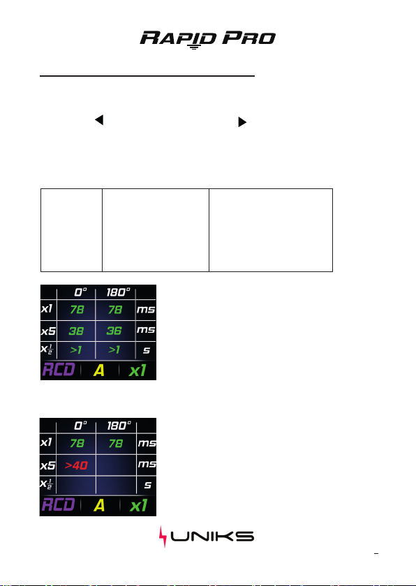
3. Residual Current (RCD) type A, AC and F also in AUTO mode with
CONTACT VOLTAGE measurement
4. Z LOOP (Global earth resistance in TT system and impedance L-Pe
in TN with short circuit current )
5. Short circuit current
6. Voltage harmonics up to 49 th
7. THD% (Total harmonics Distoron)
8. Frequency of the fundamental Harmonics and up to 49 th
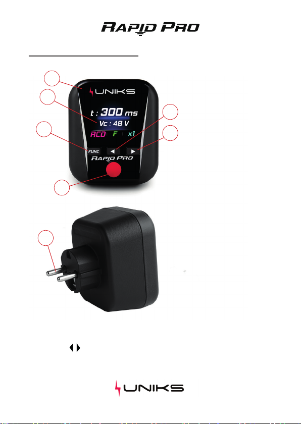
Funcon can be selected thorugh the dedicated buon .Sub funcon fea-
tures can be selected through the arrow buon for example for selecng
the RCD type or evaluate dierent harmonics. The instruments is powered
from the line and due to the SUPERCAP technology can keep the power
even when disconnected from the line .Fully charged supercap allow 45
second aer switch o from the line.This allow the user to read the value
aer the RCD is tripped out(with tripping me) or when is dicult to read
the display value
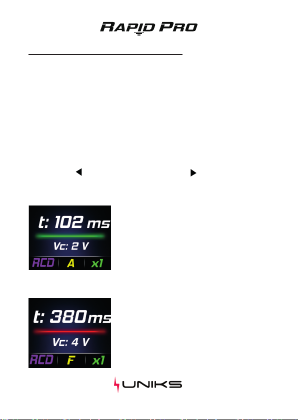
Outcome are always GREEN when the measured value is correct in accor-
ding the local regulamentaon or RED when the test is not passed.
In the SOCKET TEST uncorrect value the instruments generate also a
sound allarm.

6
PRODUCT DESCRIPTION
Descrizione dei tasti
Funcon buon allow to select the measure. Display shows the following features:
Socket Test / VOLT - RCD - LOOP - Harmonics / Memory.
Arrow buon ,allow to select subparameters for test and read the memory or to
analyze the harmonics value up to 49th. Red buon can start the RCD test or LOOP
Resistance ( no trip RCD).
1
2
3
4
5
6
7
Legend:
1. Anscratch glass
2. Display TFT 1,77”
3. Funcon
4. TEST
5. subfeatures selecon
6. subfeatures selecon
7. SCHUKO plug

7
VOLT e SOCKET TEST
Fig. 1
Fig. 2 Fig. 3
Legend:
1. Anscratch glass
2. Display TFT 1,77”
3. Funcon
4. TEST
5. subfeatures selecon
6. subfeatures selecon
7. SCHUKO plug
This feature measure Voltage between phase and neutral and test the socket wiring
in according to local requirement.
Operaon
Plug the instruments in the socket and select Voltage
funcon with buon.Voltage between Phase and
Neutral will be shown at display if socket is correctly
wired and voltage contact is <50V (Fig 1) error due
to the uncorrect wiring is shown(Fig 2 e 3). Green bar
indicate every parameter is correct. Frequency can be
shown through buon .
Wiring Error ( bar is Red and
sound allarm)
• Phase - Neutral Reverse
• Phase - Ground Reverse
• Open Neutral
• No Ground
• Voltage contact >50V
Soluon
Adjust the socket wiring
Connect Neutral wire
Check Earth connecon
Dangerous Voltage on mass

8
RCD (RESIDUAL CURRENT DEVICE)
Fig. 5
Fig. 4
This feature allow test of RCD according EC/EN 61557-6 with tripping me and
Voltage contact. Test Current of 30 mA is injected through the ground for type A ,
AC and F.
Test Mode:
• x1 I∆n –Test with 30mA
• x5 I∆n –Test with 150mA
• AUTO –Test sequence x1/2 - x1/2 180° - x1 - x1 180° - x5 - x5 180°
RCD x1 , x5
Connect RapidPro to the socket and press FUNC in order to select RCD funcon.
Press the buon for select the type of RCD and buon for select the current
(x1,x5) Press RED buon for 3 second for start the measure.
Tripping Time is shown on the display and Gre-
en bar means the test is performed correctly
Vc is the contact Voltage.
If Contact Voltage >50V the RCD tripping test
will be stopped and the bar became RED
Display shown tripping me is higher than the
limit standard and Red Bar means outcome
NOT OK (Fig 5).
Vc is the Contact Voltage.

9
RCD (RESIDUAL CURRENT DEVICE)
STEP 1
STEP 2
STEP 3
STEP 4
STEP 5
STEP 6
I∆n x1 0°
I∆n x1 180°
I∆n x5 0°
I∆n x5 180°
I∆n x1/2 0°
I∆n x1/2 180°
OK IF <300 ms
OK IF <300 ms
OK IF <40 ms
OK IF <40 ms
OK IF >1000 ms
OK IF >1000 ms
Fig. 7
Fig. 6
AUTO funcon
Plug the instrument in the socket and press FUNC for select RCD funcon. Press
arrow buon for select type of RCD and buon for select funcon AUTO .
Start measuring by pressing the Red buon,The instruments will execute all test in
sequence when you re-arm the RCD and voltage is on.
AUTO mode consist of 6 test in the folowing sequence:
Display Show RCD tripping me in ms. For every
STEPtripping me in ms will be shown. GREEN (Fig
6) if the test and tripping me are conform to local
tripping me regulamentaon.
Value in RED (Fig 7) means the test is not conform
to the local guideline and the test will be stopped.

10
LOOP
Fig. 8 Fig. 9
The measurament is performed according IEC/EN61557-3 it measure impedance
between Phase and Ground withouth RCD trip. Test Mode:
• TT Measure Earth Resistance (Ω) and Contact Voltage (V) Fig.8
• TN Measure Impedance Z L-Pe (Ω) and Ipsc prospecve short circuit current
(A) Fig.9
• Std Test with 15mA nominal current
• Low Test with 6mA. Use this setup if during the test the RCD trip due to the
presence of leackage current in the electric system under test.
LOOP FUNCTION
Plug Rapid PRO in the socket and press FUNC buon for select LOOP. Press buon
for select TT or TN and press buon for select TEST STD or LOW.
Press the RED buon for 2 second to start the measurement
During the LOOP measurement, if the SUPER CAP is not
fully charged, the Display may switch o or decrease the
intensity, however the measurement will be performed and
shown at the end.

11
LOOP TT e TN
Re Rt
L
N
Pe
RCD
Rt
L
N
Pe
TERRA
BT MT
BT MT
RCD
FUSE
Rt ≤ Vc
I∆n
Re Rt
L
N
Pe
RCD
Rt
L
N
Pe
TERRA
BT MT
BT MT
RCD
FUSE
TT SYSTEM
TN-S SYSTEM
Z line - PE impedance measurement in TT system
Z: Global Earth Resistance
Vc: Contact Voltage
NOTA: Limit for earth ground resistance is dened as:
Vc:Contact Voltage Limit (50V o 25V)
I∆n: Nominal RCD current
Impedance measurement Zs L-pe in TN system
Z: Fault Ground Impedance L-Pe
Ipsc: Prospecve short circuit current (for check correct sizing of MCB or FUSE
protecng the system)

12
HAR VOLTAGE HARMONICS
Fig. 10 Fig. 11
This funcon allow to check Voltage quality and harmonics up to 49th .
TEST MODE:
• Fund Fundamental harmonic h1 (red), his frequency (~50Hz) and THD%
Indicate total harmonic distorsion of voltage supply (Fig. 10).
• h2....50 Show VOLTAGE value TRMS of selected harmonics (red), his frequen-
cy and percentage (%) compared to h1 Fundamental 50Hz (Fig. 11)
HARMONICS FUNCTION
Plug Rapid Pro in to the socket and choose Har funcon by pressing FUNC buon.
Press for select harmonics higher or buon for select back to h1
Is it possible to disconnect RapidPro from the supply power for easilly read and
analyze the measurements unl the SUPERCAP discharge (60 second when fully
charged).

13
MEM Memory / REPORT
MEMORY
Column N ° indicates the measurement number
(Fig. 13).
The FUNC column indicates the saved measure-
ment with its sengs.
The Value column indicates the outcome of the
measurement.
The result of the RCD measurement is indicated:
GREEN if the result is OK
RED if the result is NO OK.
Fig. 12
Fig. 13
The instruments automacally save RCD and LOOP measurement in MEM area.
Press FUNC buon for enter MEM page. Press buon or for move through the
saved data or press simultaneously to clear the memory.
It will be possible to store 64 consecuve measures.
By pressing the RED buon you can generate a QR CODE for the generaon of
REPORTS (Fig. 12). The 64 posions can be organized in chronological order. The last
measurement will always be saved in the rst free CELL in ascending order (1… 64)..
surement for day of use . Last measure will be saved in the rst Memory Slot free
(1…64) or in the last cell if memory is full scaling all the other.
REPORT CREATE
Press the RED buon to generate the QR CODE.
Scan the QR CODE with your smartphone to
enter your RESERVED AREA to download data
and create REPORTS.
All saved measurements will be automacally
inserted into a REPORT.

14
TECHNICAL DATA
IEC/EN61557-6
IEC/EN61557-3
Voltage L-Pe 190÷265V - Frequency 50Hz 5%
RCD
LOOP (Fault Loop Impedance)
Voltage L-Pe 190÷265V - Frequency 50Hz 5%
Std Current test 15mA
LOW Test Current 6mA
RANGE (Ω) Resoluon (Ω) Accuracy
Type(RCD) RISOLUZIONE PRECISIONE
Open Ground or Neutral,Phase/Neutral Phase/Ground reverse - Vc>50V
Socket Test Voltage L-N 190÷265V
0.01 ÷ 9.99
10 ÷ 99.9
100 ÷ 999
AC , A , F
Time
Crest Factor 1,5 ; Frequency 42 ÷ 69.0 Hz 5%
Voltage AC TRMS (Phase-Neutral)
RANGE (V) Resoluon (V) Accuracy
120 ÷ 265 1
0.01
0.1
1
Voltage L-N 190÷265V - Frequency 50Hz 5%
Frequency
RANGE (Hz) Resoluon (Hz) Accuracy
42 ÷ 69 0.1
1 ÷ 50th Harmonics <0.8V will not be shown
Voltage Harmonics
RANGE (V) Resoluon(V) Accuracy
0,8 ÷ 256 0.1
(5.0% + 8 dgt)
(5.0% + 8 dgt)
(5.0% + 8 dgt)
(0.0% + 5%I∆n)
(2 ms + 2 dgt)
<0.1I∆n
0.1 ms
(8.0% + 12 dgt)
(1.0% + 3 dgt)
(2.0% + 1 dgt)
(3.0% + 5 dgt)

15
TECHNICAL SPECIFICATION
INPUT:
Overvoltage Category:
Max Voltage input:
INPUT:
Measures Guidelines:
Safety Guidelines :
EMC:
Display and Memory:
Display:
Memory Slot:
Enviromental Specicaon:
Reference Temperature:
Operaonal Temperature:
Maximum Humidity:
Stock temperature:
Stock Humidity:
Mechanical Characteriscs:
Size:
Weight:
CAT III 300V verso terra
265V AC
IEC/EN61557-3
IEC/EN61557-6
IEC/EN61010-1
IEC/EN61010-2-030
IEC/EN61326-1
TFT 1,77” Displau
64
23°C ÷ 5°C
5°C ÷ 40°C
<80%RH
20°C ÷ 60°C
<80%RH
(81,5 x 70 x 83) mm
110gr

16
ADAPTERS
The Rapid Pro can be connected to various adapters on the market such as exten-
sion cords or adapters for sockets other than the Schuko (Fig. 14).
The use of an extension cord can help the operator perform LOOP or RCD measure-
ments in environments where it is dicult to reach the socket for tesng.
UNIKS Srl is not responsible for malfuncons due to adapters.
Fig. 14

17
WARRANTY
• This tool is guaranteed against any defect in material and workmanship, in
accordance with the general condions of sale. During the warranty period,
defecve parts can be replaced, but the manufacturer reserves the right
to repair or replace the product. If the instrument must be returned to the
aer-sales service or to a retailer, the transport is charged to the Customer.
The shipment must, in any case, be previously agreed. Aached to the
shipment must always be inserted an explanatory note about the reasons
for sending the instrument. For shipping use only the original packaging. Any
damage caused by the use of non-original packaging will be charged to the
Customer. The manufacturer declines all responsibility for damage caused to
persons or objects.
• The warranty is not applied in the following cases:
• Repair and/or replacement of accessories and baery (not covered by war-
ranty).
• Repairs that are necessary due to incorrect use of the instrument or its use
with incompable equipment.
• Repairs that are necessary due to inadequate packaging.
• Repairs that are necessary due to intervenons carried out by unauthorized
personnel.
• Changes made to the instrument without the explicit permission of the
manufacturer.
• Use not covered by the instrument specicaons or user manual.
• The contents of this manual may not be reproduced in any form without the
manufacturer’s permission.
• Our products are patented and trademarks registered. The manufacturer
reserves the right to make changes to specicaons and prices if this is due to
technological improvements.

18
ASSISTANCE
If the instrument does not work properly, before contacng the Service Depart-
ment, check the status of the socket and the casing. If the instrument connues
to malfuncon, check if the procedure for using it complies with what is indicated
in this manual. If the instrument is to be returned to the aer-sales service or to a
retailer, the transport is charged to the Customer. The shipment must, in any case,
be previously agreed.
Aached to the shipment must always be inserted an explanatory note about the
reasons for sending the instrument. For shipping use only the original packaging;
any damage caused by the use of non-original packaging will be charged to the
Customer.

19

www.uniks.it
Uniks Srl
Via Viori 57, 48018 Faenza (RA) – Italia
Phone +39 0546 623002
Fax +39 0546 6236691
P.IVA 02627000397
REA: RA - 218481
mail [email protected]
Other manuals for RAPID PRO
1
Table of contents
Other Uniks Test Equipment manuals
Popular Test Equipment manuals by other brands

Tennant
Tennant Pro 2.0 quick start guide

BGS technic
BGS technic 67242 instruction manual

Apera Instruments
Apera Instruments Premium ORP5 manual

Teledyne Lecroy
Teledyne Lecroy LabMaster 10 Zi-A Getting started guide

Gedore
Gedore CL10 operating instructions

Furukawa electric
Furukawa electric FITEL S123M8 user manual