VEVOR DP1006L User manual

Technical Support and E-Warranty Certificate www.vevor.com/support
BENCH DRILL PRESS
INSTRUCTION MANUAL
MODEL:DP1006L
We continue to be committed to provide you tools with competitive price.
"Save Half", "Half Price" or any other similar expressions used by us only represents an
estimate of savings you might benefit from buying certain tools with us compared to the major
top brands and doses not necessarily mean to cover all categories of tools offered by us. You
are kindly reminded to verify carefully when you are placing an order with us if you are
actually saving half in comparison with the top major brands.

- 1 -
MODEL:DP1006L
INSTRUCTIVO DE OPERACIÓN,CENTROS DE SERVICIO Y PÓLIZA DE GARANTÍA.
ADVERTENCIA: LÉASE ESTE INSTRUCTIVO ANTES DE USAR EL PRODUCTO.
Have product questions? Need technical support? Please feel free to
contact us:
CustomerService@vevor.com
NEED HELP? CONTACT US!
This is the original instruction, please read all manual instructions
carefully before operating. VEVOR reserves a clear interpretation of our
user manual. The appearance of the product shall be subject to the
product you received. Please forgive us that we won't inform you again if
there are any technology or software updates on our product.
BENCH DRILL PRESS

- 2 -
TABLE OF CONTENTS
SECTION PAGE
PRODUCT SPECIFICATIONS................................................................................2
SAFETY GUIDELINES -DEFINITIONS...................................................................3
PROPOSITION 65 WARNING............................................................................... 5
POWER TOOL SAFETY..........................................................................................5
ADDITIONAL SAFETY RULES FOR DRILL PRESSES..........................................9
ELECTRICAL REQUIREMENTS AND SAFETY....................................................11
TOOLS NEEDED FOR ASSEMBLY......................................................................15
CARTON CONTENTS..........................................................................................15
KNOW YOUR DRILL PRESS................................................................................18
GLOSSARY OF TERMS.......................................................................................19
ASSEMBLY AND ADJUSTMENTS .......................................................................21
OPERATION ........................................................................................................32
MAINTENANCE....................................................................................................40
ACCESSORIES AND ATTACHMENTS ................................................................41
TROUBLESHOOTING GUIDE..............................................................................42
PARTS LIST..........................................................................................................45
PRODUCT SPECIFICATIONS
MOTOR
Power Source
120 V, 60 Hz, 3.2 A
Speed (No load)
1720 RPM
Type
Induction
Volts
120 volts AC only
TABLE
Size
7-5/8 in. x 6-1/2 in.
(190 x 165 mm)
BASE
Size
12-1/2 in. x 7-5/16 in.
(319 x 186 mm)
Chuck to Column
5 in. (130 mm)
Chuck to Base
16-1/8 in. (445 mm)

- 3 -
LAMP
Yes
Spindle Travel
2 in. (50 mm)
Speeds (RPM)
610~2800 RPM
Chuck Size
1/2 in. (13 mm)
Column Size
1-718 in. (48 mm)
To avoid electrical hazards,fire hazards or damage to the tool, use proper
circuit protection. Use a separate electrical circuit for your tools. The drill
press is wired at the factory for 120 Volt operation. It must be connected to
a 120 V,3.2 AMP branch circuit and use a 3.2 AMP time delay fuse or
circuit breaker. To avoid shock or fire, replace power cord immediately if it
is worn, cut or damaged in any way.
SAVE THESE INSTRUCTIONS
SAFETY GUIDELINES-DEFINITIONS
WARNING ICONS
Your power tool and its Instruction ManuaI may contain "WARNING
ICONS" (a picture symbol intended to alert you to and/or instruct you how
to avoid a potentially hazardous condition). Understanding and heeding
these symbols will help you operate your tool better and safer. Shown
below are some of the symbols you may see.
SAFETY ALERT: Precautions that involve your safety.
PROHIBITION
WEAR EYE PROTECTION: Always wear safety goggles or
safety glasses with
side shields.

- 4 -
WEAR RESPIRATORY AND HEARING PROTECTION:
Always wear respiratory and
hearing protection.
READ AND UNDERSTAND INSTRUCTION MANUAL: To
reduce the risk of injury, user and all bystanders must read
and understand instruction manual before using this product.
KEEP HANDS AWAY FROM THE MOVING PART AND
CUTTING SURFACE: Failure to keep your hands away from
the moving part and to cut surface will result in serious
personal injury.
SUPPORT AND CLAMP WORK
DANGER: Indicates an imminently hazardous situation which,
if not avoided, will result in death or serious injury.
WARNING: Indicates a potentially hazardous situation which,
if not avoided, could result in death or serious injury.
CAUTION: Indicates a potentially hazardous situation which, if
not avoided, may result in minor or moderate injury.
NOTICE: Used without the safety alert symbol indicates
potentially hazardous situation which, if not avoided, may
result in property damage.

- 5 -
PROPOSITION 65 WARNING
Drilling,sawing,sanding or machining wood products can expose you to
wood dust, a substance known to the State of California to cause cancer.
Avoid inhaling wood dust or use a dust mask or other safeguards for
personal protection. For more information go to
www.P65Warnings.ca.gov/wood Some examples of these chemicals are:
● Lead from lead-based paints,
● Crystalline silica from bricks and cement and other masonry products,
and.
● Arsenic and chromium from chemically-treated lumber.
Your risk from these exposures varies depending on how often you do this
type of work. To reduce your exposure to these chemicals:work in a well
ventilated area and work with approved safety equipment,such as dust
masks that are specially designed to filter out microscopic particles.
Handling the power cord on this product mayexpose you to chemicals
known to the state of California to cause cancer and birth defects or other
reproductive harm.Wash hands after handling. For more information go to:
www.P65Warnings.ca.gov
POWER TOOL SAFETY
GENERAL SAFETY INSTRUCTIONS BEFORE USING THIS POWER
TOOL
Safety is a combination of common sense, staying alert and knowing how
to use your power tool.

- 6 -
● To avoid mistakes that could cause
serious injury,do not plug the tool in until you have read and understood the
following.
● Read all instructions before operating product.Failure to follow all
instructions listed below may result in electric shock,fire and/or serious
injury.
1. READ and become familiar with the entire Instruction Manual.
LEARN the tool's application,limitations and possible hazards.
2.KEEP GUARDS IN PLACE and in working order.
3.REMOVE ADJUSTING KEYS AND WRENCHES. Form the habit of
checking to see that keys and adjusting wrenches are removed from the
tool before turning ON.
4.KEEP WORK AREA CLEAN. Cluttered areas and benches invite
accidents.
5.DO NOT USE IT IN DANGEROUS ENVIRONMENTS. Do not use power
tools in damp locations or expose them to rain or snow. Keep the work
area well-lit.
6.KEEP CHILDREN AWAY. All visitors and bystanders should be kept a
safe distance from work area.
7.MAKE WORKSHOP CHILD PROOF with padlocks, master switches or
by removing starter keys.
8. DO NOT FORCE THE TOOL. It will do the job better and safer at the
rate for which it was designed.
9. USE THE RIGHT TOOL. Do not force the tool or an attachment to do a
job for which it was not designed.
10. USE PROPER EXTENSION CORDS.
Make sure your extension cord is in good condition. When using an
extension cord, be sure to use one heavy enough to carry the current
your product will draw. An undersized cord will result in a drop in line
voltage and in loss of power which will cause the tool to overheat. The
table on page 9 shows the correct size to use depending on cord length

- 7 -
and nameplate ampere rating. If in doubt, use the next heavier
gauge.The smaller the gauge number, the heavier the cord.
11. WEAR PROPER APPAREL. Do not wear loose clothing, gloves,
neckties, rings, bracelets or other jewelry which may get caught in
moving parts.Nonslip footwear is recommended.Wear protective hair
covering to contain long hair.
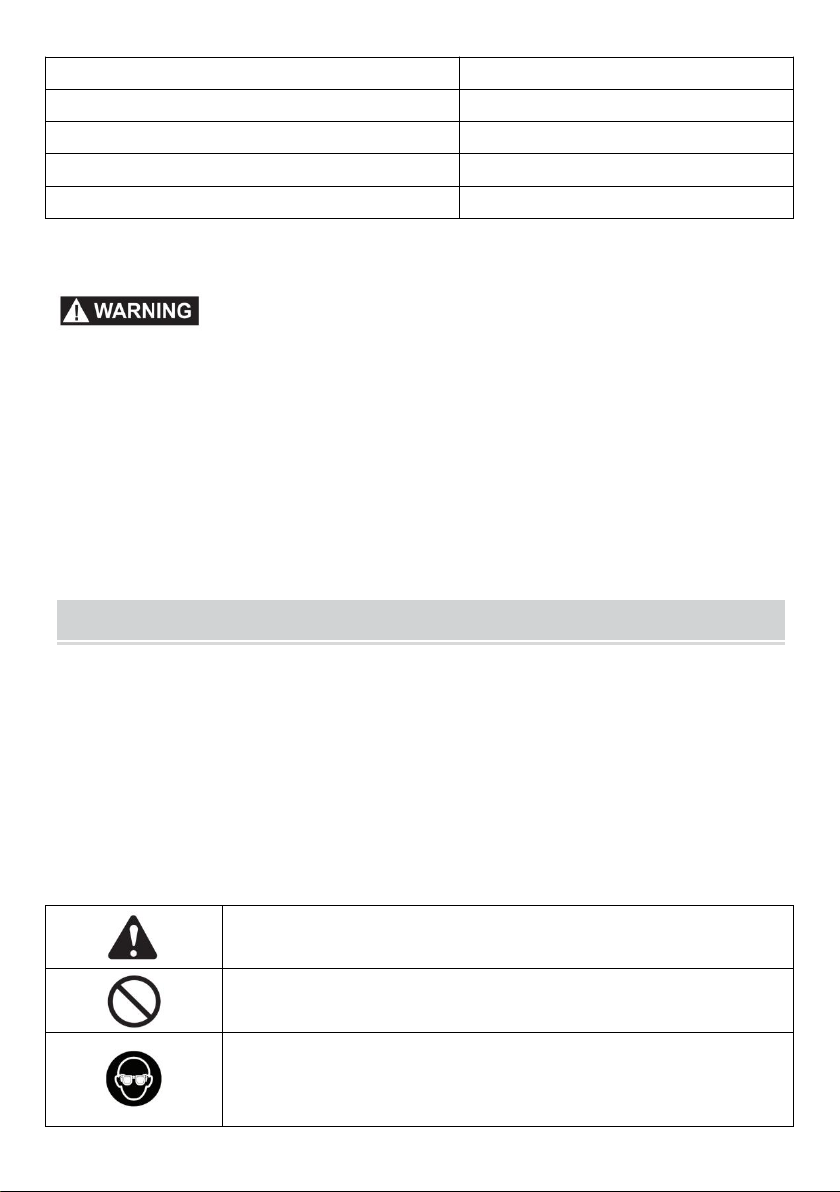
12. ALWAYS WEAR EYE PROTECTION. Any power tool can throw
foreign objects into the eyes and could cause permanent eye damage.
ALWAYS wear Safety Goggles (not glasses) that comply with
ANSISafetystandardZ87.1.Everyday eyeglasses have only
impact-resistant lenses. They ARE NOT safety glasses.
NOTE: Glasses or goggles not in compliance with ANSI Z87.1 could
seriously injure you when they break.
13. WEAR A FACE MASK OR DUST MASK. Sawing operation
produces dust.
14. SECURE WORK. Use clamps or a vise to hold work when
practical. It is safer than using your hand and it frees both hands to
operate the tool.
15. DISCONNECT TOOLS FROM POWER SOURCE before servicing,
and when changing accessories such as blades, bits and cutters.
16. REDUCE THE RISK OF UNINTENTIONAL STARTING. Make sure
switch is in the OFF position before plugging the tool in.
17. USE RECOMMENDED ACCESSORIES.
Consult this Instruction Manual for recommended accessories.The use
of improper accessories may cause risk of injury to yourself or others.
18. NEVER STAND ON THE TOOL. Serious injury could occur if the tool
is tipped or if the cutting tool is unintentionally contacted.
19. CHECK FOR DAMAGED PARTS. Before further use of the tool, a
guard or other part that is damaged should be carefully checked to
determine that it will operate properly and perform its intended function
-check for alignment of moving parts, binding of moving parts,breakage of

- 8 -
parts,mounting and any other conditions that may affect its operation. A
guard or other part that is damaged should be properly repaired or
replaced.
20.NEVER LEAVE THE TOOL RUNNING UNATTENDED. TURN THE
POWER “OFF”. Do not walk away from a running tool until the blade
comes to a complete stop and the tool is unplugged from the power
source.
21. DO NOT OVERREACH. Keep proper footing and balance at all times.
22. MAINTAIN TOOLS WITH CARE. Keep tools sharp and clean for best
and safest performance.Follow instructions for lubricating and changing
accessories.
23. DO NOT use power tool in presence of flammable liquids or gases.
24. DO NOT operate the tool if you are under the influence of any drugs,
alcohol or medication that could affect your ability to use the tool properly.
25. Dust generated from certain materials can be hazardous to your health.
Always operate saw in well-ventilated area and provide for proper dust
removal.
26.
People with electronic devices, such as pacemakers,should consult their
physician(s) before using this product. Operation of electrical equipment in
close proximity to a heart pacemaker could cause interference or failure of
the pacemaker.
27. WEAR HEARING PROTECTION to reduce the risk of induced
hearing loss.

- 9 -
ADDITIONAL SAFETY RULES FOR DRILL PRESS
Following good safety practices when using drill presses is a must.Make a
habit of including safety in all your activities.
READALLINSTRUCTIONSBEFORE OPERATING PRODUCT.
FAILURETO FOLLOW ALL INSTRUCTIONS LISTED BELOW MAY
RESULT IN ELECTRIC SHOCK, FIRE AND OR SERIOUS INJURY.
Do not operate this tool until it is assembled and installed according to the
instructions.
1.YOUR DRILL PRESS MUST BE BOLTED securely to a workbench.In
addition, if there is any tendency for your drill press to move during
certain operations,bolt the workbench to the floor.
2. DO NOT try to drill material too small to be securely held.
3. ALWAYS keep hands out of the path of a drill bit. Avoid awkward hand
positions where a sudden slip could cause your hand to move into the
drill bit.
4. DO NOT install or use any drill bit that exceeds 7 in.(175 mm) in length
or extends 6 in.(150 mm)below the chuck jaws.They can suddenly bend
outward or break.
5. DO NOT USE wire wheels, router bits, shaper cutters, circle(fly)cutters,
or rotary planers on this drill press.
6. WHEN cutting a large piece of material, make sure it is fully supported at
the table height.
7. NEVER hold the workpiece by hand. Secure the workpiece with a clamp
or another appropriate fixture if it is not long enough to be braced against
the table column.
8. CLAMP THE WORKPIECE OR BRACE IT against the left side of the
column to prevent rotation. If it is too short or the table is tilted,clamp it
solidly to the table.
9. IF THE WORKPIECE overhangs the table such that it will fall or tip if not
held,clamp it to the table or provide auxiliary support.

- 10 -
10. SECURE THE WORK. Use clamps or a vise to hold the work. It's safer
than using your hand and it frees both hands to operate tool.
11. WHEN using a drill press vise,always fasten to the table.
12. MAKE SURE all clamps and locks are firmly tightened before drilling.
13. MAKE SURE there are no nails or foreign objects in the part of the
workpiece to be drilled.
14. SECURELY LOCK THE HEAD and table support to the column,and
the table to the table support before operating the drill press.
15. NEVER turn your drill press on before clearing the table of all objects
(tools, scraps of wood,etc.). Remove material or debris from the area
that might be ignited by hot chips.
16. Crowded,cluttered work areas that can cause tripping or loss of
balance are particularly dangerous.
17. BEFORE STARTING the operation, jog the motor switch to make sure
the drill bit does not wobble or vibrate.
18. LET THE SPINDLE REACH FULL SPEED before starting to drill. If
your drill press makes an unfamiliar noise or if it vibrates excessively,
stop immediately, tum the drill press off and unplug it.Do not restart the
unit until the problem is corrected.
19. DO NOT perform layout assembly or set up work on the table while the
drill press is in operation.
20. USE THE RECOMMENDED SPEED for any drill press accessory and
for different workpiece materials. READ THE INSTRUCTIONS that
come with the accessory.
21.WHEN DRILLING large diameter holes, clamp the workpiece firmly to
the table. Otherwise,the bit may grab and spin the workpiece at high
speeds. DO NOT USE fly cutters or multiple-part hole cutters, as they
can come apart or become unbalanced in use.
22. DO NOT use bits with screw tips. These bits will pull the workpiece up
from the table and start to spin, causing a serious risk of injury.
23. MAKE SURE the spindle has come to a complete stop before touching
the workpiece.

- 11 -
24. TO AVOID INJURY from accidental starting, always turn the switch
"OFF"and unplug the drill press before installing or removing any
accessory or attachment or making any adjustments.
25. Be sure the chuck is tightly secured to the spindle.
26. USE ONLY THE SELF-EJECTING TYPE CHUCK KEY as provided
with the drill press. Tighten the bit securely in the chuck. The chuck key
can be thrown at a high velocity if not removed, causing a risk of injury.
27. DO NOT FORCE DRILLING. The tool will do the job better and safer at
the rate for which it was intended.
28. If the bit binds in the workpiece, release the on/off switch immediately.
Unplug the tool, then free the bit from the workpiece. Do not try to free a
jammed bit by starting and stopping the tool.
29. DO NOT touch the drill bit or cuttings. The drill bit and cuttings are hot
immediately after drilling.
30. ALWAYS shut off, unplug and lock the drill press, if a lock in available,
and store the key.
ELECTRICAL REQUIREMENTS AND SAFETY
POWER SUPPLY AND MOTOR SPECIFICATIONS
To avoid electrical hazards,fire hazards, or damage to the tool, use proper
circuit protection. Use a separate electrical circuit for your tool.Your grinder
is wired at the factory for 120 V operation.Connect to a 120V,3.2 Amp
circuit and use a 3.2 Amp time delay fuse or circuit breaker.To avoid shock
or fire,if power cord is worn,cut, or damaged in any way,have it replaced
immediately.
GROUNDING INSTRUCTIONS

- 12 -
This tool must be grounded while in use to protect the operator from
electrical shock.
IN THE EVENT OF A MALFUNCTION OR BREAKDOWN, grounding
provides a path of least resistance for electric currents and reduces the risk
of electric shock. This tool is equipped with an electrical cord that has an
equipment-grounding conductor and a grounding plug.The plug must be
plugged into a matching receptacle that is properly installed and grounded
in accordance with all local codes and ordinances.
DO NOT MODIFY THE PLUG PROVIDED. If it will not fit the receptacle,
have the proper receptacle installed by a qualified electrician.
IMPROPER CONNECTION of the equipment grounding conductor can
result in risk of electric shock. The conductor with the green insulation (with
or without yellow stripes) is the equipment grounding conductor. If repair or
replacement of the electrical cord or plug is necessary,do not connect the
equipment grounding conductor to a live terminal.
CHECK with a qualified electrician or service person if you do not
completely understand the grounding instructions,or if you are not certain
the tool is properly grounded.
USE only 3-wire extension cords that have three-pronged grounding
plugs with three-pole receptacles that accept the tool's plug.Repair or
replace damaged or worn cords immediately.
Use a separate electrical circuit for your tool. This circuit must not be less
than#18 wire and should be protected with a 3.2 Amp time lag fuse.Before
connecting the motor to the power line,make sure the switch is in the off
position and the electric current is rated the same as the current stamped
on the motor nameplate. Running at a lower voltage will damage the motor.

- 13 -
GUIDELINES FOR EXTENSION CORDS USE THE PROPER
EXTENSION CORD. Make sure your extension cord is in good condition.
Use an extension cord heavy enough to carry the current your product will
draw.An undersized cord will cause a drop in line voltage resulting in loss
of power, overheating and burning out of the motor. The table below shows
the correct size to use depending on cord length and nameplate ampere
rating. If in doubt, use the next heavier gauge. The smaller the gauge
number, the heavier the cord.
Make sure your extension cord is properly wired and in good condition.
Always replace a damaged extension cord or have it repaired by a qualified
technician before using it. Protect your extension cords from sharp objects,
excessive heat and damp or wet areas.
MINIMUM GAUGE FOR EXTENSION CORDS (AWG)
(When usng 120 volts only)
Ampere Rating
Total length of Cord
More Than Not More Than
25 50 100 150 ft.
(7.62 15.24 30.48 45.72 m)
AWG- American Wire Gauge
0 6
18 16 16 14
6 10
18 16 14 12
10 12
16 16 14 12
12 16
14 12 Not Recommended

- 14 -
This tool is for indoor use only. Do not expose to rain or use in damp
locations.
This tool is intended for use on a circuit that has a receptacle like the one
illustrated in Fig.1.Fig.1 shows a three-pronged electrical plug and
receptacle that has a grounding conductor. If a properly grounded
receptacle is not available,an adapter (Fig.2) can be used to temporarily
connect this plug to a two-contact grounded receptacle. The adapter (Fig.2)
has a rigid lug extending from it that MUST be connected to a permanent
earth ground,such as a properly grounded receptacle box.
In all cases, make certain the receptacle is properly grounded. If you are
not sure, have a qualified electrician check the receptacle.

- 15 -
TOOLS NEEDED FOR ASSEMBLY
CARTON CONTENTS
UNPACKING AND CHECKING CONTENTS
Carefully unpack the drill press and all its parts,and compare against the
list below and the illustration on the next page. Place the drill press on a
secure surface and examine it carefully.

- 16 -
To avoid injury from unexpected starting or electrical shock, do not
plug the power cord into a source of power during unpacking and
assembly. The cord must remain unplugged whenever you are
adjusting/assembling the drill press.
The drill press is heavy and should be lifted with care. If needed, get
the assistance of someone to lift and move the drill press.
If any part is missing or damaged, do not attempt to assemble the drill
press, or plug in the power cord until the missing or damaged part is
correctly replaced.
TABLE OF LOOSE PARTS
ITEM
DESCRIPTION
Q’TY
A.
Head Assembly
1
B.
Table Assembly
1
C.
Base
1
D.
Feed Handles
3
E.
Chuck & Key Hardware
Chuck
1
Chuck Key
1
F.
Column Assembly
1
G.
Hardware Bag
Lock Handle
1
Crank Handle
1
Worm Gear
1
Hex Wrenches
2
Hex Bolts
3
Rack
1
Rack Ring
1
H.
AA Batteries
2

- 17 -

- 18 -
KNOW YOUR DRILL PRESS

- 19 -
GLOSSARY OF TERMS
BASE-Supports drill press.For additional stability, holes are provided in the
base to bolt drill press to the floor.(See "ADDITIONAL SAFETY RULES
FOR DRILL PRESSES".)
BACKUP MATERIAL-Apiece of scrap wood placed between the
workpiece and table.The backup board prevents wood in the workpiece
from splintering when the drill passes through the backside of the
workpiece.It also prevents drilling into the table top.
PULLEY COVER-Coversthepulleysandbelt during operation of the drill
press.
BELT TENSION-Refer to the "Assembly"Section,"Installing and
Tensioning Belt."
BELT TENSION LOCK KNOBS-Tightening the knobs locks the motor
bracket support and the belt tension handle,maintaining correct belt
distance and tension.
BEVEL SCALE-Shows degree of table tilt for bevel operations. The scale
is mounted on the side of the arm.
CHUCK-Holds a drill bit or other recommended accessory to perform
desired operations.
CHUCK KEY-Aself-ejecting chuck key which will pop out of the chuck
when you let go of it.This action is designed to help prevent throwing of the
chuck key from the chuck when the power is turned "ON."Do not use any
other key as a substitute; order a new one if damaged or lost.
COLUMN ASSEMBLY-Connects the head, table,and base on a one-piece
tube for easy alignment and movement. Mounts to base.
COLUMN COLLAR-Holds the rack to the column.Rack remains movable
in the collar to permit table support movements.
DEPTH SCALE STOP NUTS-Lock the spindle to a selected depth.
DEPTH SCALE-Indicates depth of hole being drilled.
DRILL BIT-The cutting tool used in the drill press to make holes in a
workpiece.
Table of contents
Other VEVOR Power Tools manuals

VEVOR
VEVOR TLM38388 User manual

VEVOR
VEVOR ALK-T1 User manual

VEVOR
VEVOR 2822C Operation instructions

VEVOR
VEVOR G8504C User manual

VEVOR
VEVOR P8001 User manual

VEVOR
VEVOR XC6527 User manual

VEVOR
VEVOR JX1.3-30 User manual

VEVOR
VEVOR 18150FTLB User manual

VEVOR
VEVOR Thicknesser M1B-LS-3301 User manual

VEVOR
VEVOR ALK-T2 User manual