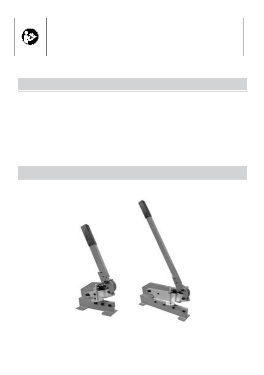
Model..................................................................................................HS-5
Blade length...............................................................................5" (130 mm)
Sheet steel................................................................................0.24" (6 mm)
Flat steel...................................................................2.76"x0.24" (70x6 mm)
Round steel.............................................................................0.43" (11 mm)
Model...................................................................................................HS-8
Blade length..............................................................................8" (203 mm)
Sheet steel...............................................................................0.24" (6 mm)
Flat steel...................................................................2.76"x0.24" (70x6 mm)
Round steel............................................................................0.51" (13 mm)
Model..................................................................................................HS-12
Blade length.............................................................................12" (305 mm)
Sheet steel................................................................................0.24" (6 mm)
Flat steel...................................................................2.76"x0.24" (70x6 mm)
Round steel............................................................................0.51" (13 mm)
Standard accessories
Blades are coated with a protectant. To ensure proper fit and operation,
remove coating. Coating is easily removed with mild solvents, such as
mineral spirits, and a soft cloth. Avoid getting cleaning solutions on paint or
any of the rubber or plastic parts. Solvents may deteriorate these finishes.
Use soap and water on paint, plastic or rubber components. After cleaning,
cover all exposed surfaces with a light coating of oil.