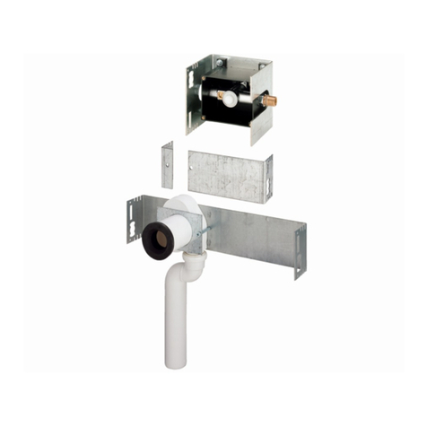
Viega 2243.10 User manual

for automated water exchange in DN 12-80 pipelines
Model Year built:
2243.10 from 03/2016
en_INT
Flush valve universal
Instructions for Use

Flush valve universal 2 from 62

Table of contents
1About these instructions for use 5
1.1 Target groups 5
1.2 Labelling of notes 5
1.3 About this translated version 6
1.4 Acronyms and notes on the text 6
2Product information 7
2.1 Safety advice 7
2.2 Intended use 7
2.2.1 Areas of use 7
2.3 Product description 7
2.3.1 Overview and description of component 7
2.3.2 Operating mode 12
2.3.3 Sound protection 16
2.3.4 Technical data 17
2.4 Information for use 18
2.4.1 Installation variations 18
2.5 Accessories and spare parts 23
3Handling 25
3.1 Transport and storage 25
3.2 Assembly information 25
3.2.1 Mounting conditions 25
3.2.2 Potential equalisation 26
3.2.3 Installation dimensions 27
3.3 Mounting 29
3.3.1 Mounting the base 29
3.3.2 Connecting the flush valve to the pipeline 34
3.3.3 Connecting electrical components 35
3.3.4 Flushing the valve 39
3.3.5 Manual functional test 40
3.3.6 Notes on wall installation 41
3.3.7 Mounting the cover 41
3.4 Commissioning 43
3.4.1 Leakage test 43
3.4.2 Configuring the control 43
3.5 Faults, faults and remedy 46
Table of contents
Flush valve universal 3 from 62

1 About these instructions for use
Trade mark rights exist for this document, further information can be
found at
viega.com/legal
.
1.1 Target groups
The information in this instruction manual is directed at the following
groups of people:
nHeating and sanitary professionals and trained personnel
nTrained electricians
nOperators
nConsumers
It is not permitted for individuals without the abovementioned training or
qualification to mount, install and, if required, service this product. This
restriction does not extend to possible operating instructions.
The installation of Viega products must take place in accordance with
the general rules of engineering and the Viega instructions for use.
1.2 Labelling of notes
Warning and advisory texts are set aside from the remainder of the text
and are labelled with the relevant pictographs.
DANGER!
This symbol warns against possible life-threatening injury.
WARNING!
This symbol warns against possible serious injury.
CAUTION!
This symbol warns against possible injury.
NOTICE!
This symbol warns against possible damage to property.
About these instructions for use
Flush valve universal 5 from 62

Notes give you additional helpful tips.
1.3 About this translated version
This instruction for use contains important information about the choice
of product or system, assembly and commissioning as well as intended
use and, if required, maintenance measures. The information about the
products, their properties and application technology are based on the
current standards in Europe (e. g. EN) and/or in Germany
(e. g. DIN/DVGW).
Some passages in the text may refer to technical codes in Europe/
Germany. These should serve as recommendations in the absence of
corresponding national regulations. The pertinent national laws, stand-
ards, regulations and guidelines, as well as other technical guidelines,
have priority over German/European guidelines in this manual: The
information is not binding for other countries and territories and should,
as mentioned, be considered as support.
1.4 Acronyms and notes on the text
WM wall-mounted
BCS building control system
CC concealed
In these instructions for use, the purpose-oriented term "water
exchange" is used instead of the term "flushing".
Acronyms
Notes on the text
About these instructions for use
Flush valve universal 6 from 62

2 Product information
2.1 Safety advice
DANGER!
Danger due to electrical current
An electric shock can lead to burns and serious injury and
even death.
– Work on the electrics may only be carried out by trained
electricians.
– Switch off the mains voltage before carrying out work on
electrical parts.
2.2 Intended use
2.2.1 Areas of use
The flush valve is intended for use in drinking water installations with
manifold or uptake conduits of dimension 12-80.
While an external flush command is applied, the control of the flush
valve automatically performs a water exchange, helping the user to
keep their water quality at drinking water level.
The control does not perform a water exchange independ-
ently or automatically. Water exchange must be triggered
by enabling the binary input referred to a potential, or the
analog voltage input (6-48 V AC/DC). This opens the inte-
grated magnet valve for as long as the signal is applied.
The flush valve must either be connected to a higher-level control, such
as building control system (= BCS) which centrally monitors the fault
and alarm message outputs and evaluates the signals, or a once-per-
week visual inspection of the alarms indicated at the control must be
ensured.
2.3 Product description
2.3.1 Overview and description of component
nFlush valve, mounted to the base support, with interior wiring
nfixing material
nSeals for inlet and drain
Scope of delivery
Product information
Flush valve universal 7 from 62

nProtective plug at water connection
nInstructions for use
1
5
2
4
3
6
Fig. 1: Overview of flush valve
1 - Flow switch
2 - Magnet valve
3 - floating switch
4 - siphon with integrated overflow monitoring (floating switch)
5 - base support
6 - control
Product information
Flush valve universal 8 from 62

1
2
5
3
47
6
8
Fig. 2: Overview of control
1 - Bush (flush command input and event signaling outputs)
2 - Bush (flush command voltage
and event signaling output 4-20 mA)
3 - flow switch bush
4 - backflow sensor bush
5 - magnet valves bushes
6 - reset button backflow
7 - test button test flushing
8 - connection for 230 V power supply
Control
Product information
Flush valve universal 9 from 62

1
2
4
3
Fig. 3: Magnet valve overview
1 - fixing flange
2 - magnetic coils
3 - flow control
4 - valve body
Magnet valve
Product information
Flush valve universal 10 from 62

1
4
3
2
Fig. 4: Flush switch, overview
1 - Flow switch
2 - union nut
3 - T-piece
4 - union nut
Flow switch
Product information
Flush valve universal 11 from 62

1
2
3
4
Fig. 5: Overview siphon
1 - lid
2 - socket
3 - drain with free discharge AB
4 - floating switch
2.3.2 Operating mode
The flush valve is intended for automated water exchange (flushing) in
the connected drinking water pipelines. The flush valve is suitable for
connection to DN 12-80 manifold or riser pipes.
One flush valve each regulates the water exchange in the cold water
and hot water pipes.
The flush valve can be placed in the following spots:
nat the end of the pipeline run
nat the end of the manifold lines
nin the supply line to the fire extinguishing systems
nIn the supply line to rarely used sections of the installation.
Siphon
Placement
Product information
Flush valve universal 12 from 62

The following additional or customer-provided components can actuate
water exchange (flushing):
nTimer
nBuilding control system (BCS)
Furthermore, the flush valve flushes all valves for 10 seconds every 72
hours (time-delayed cycle: 1.5 s open, 1.5 s closed) to prevent blocking
of valves and stagnation of the water within the valve.
Every water exchange is switched off automatically after 30
minutes.
Water exchange is actuated by:
napplication of a floating contact (closing the contact = flush com-
mand); or
napplication of 6-48 V AC/DC analog voltage, see
ÄFig. 6
.
Volume flow can be set depending on the length and nominal width of
the line. It remains constant also with pressure fluctuations. The neces-
sary flow rates pursuant to DIN 1988-600 can be set at the control unit
in increments of approx. 12 l/min. (setting range 12 l/min to 45 l/min),
see
Ä„Flowthrough volumes at flow pressure 0.3 MPa (3 bar)“
on page 45
.
The flowthrough volumes are reliably provided at a flow pressure of
0.3 MPa (3 bars) and up, see
Ä„Flowthrough (±10%)“ on page 18
.
Recommended setting
Number of active valves Dimensions (DN)
1 12–25
2 32–40
3 50–65
4 80
The drain system works as follows:
nA free drain of type AB ensures safe separation of drinking water
from wastewater pursuant to the requirements of DIN EN 1717 and
DIN 1988 -100.
nIn case of a backflow in the wastewater system, overflow monitoring
by means of an integrated floating switch (level sensor) in the siphon
prevents the actuation of a water exchange, or aborts the water
exchange in case of resulting overflowing.
Water exchange actuation
Volume flow
Drain system
Product information
Flush valve universal 13 from 62

The flush valve comprises a siphon / odour trap. No addi-
tional siphon is required outside of the flush valve.
NOTICE!
The dimension of the wastewater conduits must comply
with the specifications of DIN 1986-100.
During a water exchange, a flow switch checks whether water is dis-
charged in the proper manner. The flow switch also signals improper
flowthrough without flushing command, e.g. in case of a defective
magnet valve etc.
The following functions can be set by means of floating contacts, see
ÄFig. 6
:
nMessage: Operating / fault
nMessage: Water exchange ongoing
nMessage: Backflow
nMessage: Active valve runs / setting of flowthrough volumes
mA Connections
4 Standby
8 1 valve
12 2 valves
16 3 valves
20 4 valves
Flowthrough monitoring
Terminals for external sensor
Product information
Flush valve universal 14 from 62

1
2
3
4567
8
9
L
N
PE
10
+
_
Fig. 6: Connection diagram
1 - line L
2 - line N
3 - PE line
4 - fault (alarm)
5 - flush command (flushing)
6 - water exchange ongoing (flushing ongoing)
7 - backflow (fault backflow)
8 - flush command (6–48 V AC/DC)
9 - flowthrough volume (4–20 mA)
10 - 100–240 V AC
The outputs are digital outputs (potencial-free N.O. contacts).
The connectors 4, 6 and 7 are binary outputs which can be evaluated in
an isolated circuit.
Connector 5 is a binary input which can be actuated in an isolated cir-
cuit to carry out a water exchange.
When evaluating the switching contact 6 - water exchange ongoing
(flushing ongoing) -, note the switch-on delay of 2-3 seconds at the
beginning.
Switching the signal outputs
Product information
Flush valve universal 15 from 62

NOTICE!
The maximum load on the binary outputs is 24 V and 1 A
(max. 24 W). Do not switch loads directly via the signal out-
puts!
An analog voltage of 6–48 V AC/DC can be applied at connector 8 to
initiate a water exchange.
NOTICE!
Load the analog voltage input with minimum voltage, e.g.
100 mA at 24 V (max. 3 W).
Example: 12 V and 250 mA
Connector 9 is an analog current output 4–20 mA.
Number in the
wiring diagram
Output mes-
sage
Contact closed Contact open
- 4 - Fault or oper-
ating
Normal opera-
tion
Control current-
less, magnet
valve short-
circuited or
defective
- 6 - Water
exchange
ongoing, or
leaks
Flowthrough
> 6 l/min
No flowthrough,
or flowthrough
< 6 l/min
- 7 - Backflow Backflow sensor
is triggered or is
defective
Normal opera-
tion
2.3.3 Sound protection
All components are mounted to the mounting bracket with acoustic
insulation.
We recommend to use acoustic insulation also when
mounting the base. Place for example a rubber mat or insu-
lation material between the brickwork and the base.
Product information
Flush valve universal 16 from 62

2.3.4 Technical data
Ambient conditions
Operating temperature of the con-
trol unit
0 °C up to 50 °C
Relative humidity 5 to 95 % (non-condensing)
Storage temperature -20 °C up to 80 °C
Protection class IP54
Power supply / control
Mains voltage 100–240 V ±10 % AC
Mains frequency 50 / 60 Hz
Supply voltage internal 24 V DC SELV
Supply current Max. 1.25 A
Standby < 0.75 W
Power consumption power pack 30 W
Operating temperature 5–50 °C
Backflow sensor
Protection class IP 67
Ambient temperature -30 °C up to 80 °C
Magnet valve
Operating pressure 0.8 MPa (8 bar)
Temperature range 10–90 °C
Output state Closed in de-energized state
Protection class IP 54
Voltage 24 V DC
Product information
Flush valve universal 17 from 62

Flowthrough (±10%)
Flow pres-
sure
Valve 1
(l/min)
Valve 2
(l/min)
Valve 3
(l/min)
Valve 4
(l/min)
0.1 MPa
(1 bar)
10 19 25 30
0.2 MPa
(2 bar)
12 22 32 40
0.3 –
0.8 MPa
(3–8 bar)
12 24 35 45
2.4 Information for use
2.4.1 Installation variations
Fig. 7: Viega Steptec installation diagram
For mounting, see
Ä„Viega Steptec“ on page 30
.
Viega front-wall installations
Product information
Flush valve universal 18 from 62
Table of contents
Other Viega Control Unit manuals

Viega
Viega ManaBloc Instruction sheet

Viega
Viega 8310.0 User manual

Viega
Viega 1247.4 User manual

Viega
Viega 8133.3 User manual

Viega
Viega ProPress 22074 Instruction sheet

Viega
Viega Easytop 2275.10 User manual

Viega
Viega 2281.7 User manual

Viega
Viega G2101 User manual

Viega
Viega 2275.2 User manual

Viega
Viega 9690TW User manual

Viega
Viega Easytop 2282 User manual

Viega
Viega PureFlow Crimp Instruction sheet

Viega
Viega Multiplex Trio E User manual

Viega
Viega ProPress 304 Stainless User manual

Viega
Viega Grundfix Plus-Control User manual

Viega
Viega Easytop 2170 User manual

Viega
Viega PureFlow 2842.3ZL Instruction sheet

Viega
Viega 8655.11 User manual

Viega
Viega 8332.3 User manual

Viega
Viega 8127.3 User manual