manuals.online logo
Brands
  1. Home
  2. •
  3. Brands
  4. •
  5. Vivax Metrotech
  6. •
  7. Analytical Instrument
  8. •
  9. Vivax Metrotech vLocCam User manual

Vivax Metrotech vLocCam User manual

vLocCam Quick Start Guide (V3.0)
Disclaimer: All product availability or product accessory information is subject to change without notice.
vLocCam Receiver Display
Locating the camera head
vCamDigital Control Panel
Switch on the transmitting Sonde using the controls on
the front of the vCam control module.
Switch on by depressing “13”. Pressing “14” together
with “13” toggles the frequency through 512Hz, 640Hz
and 33kHz.
See the vCam user manual for full functions of the
control module.
Select 33kHz unless detecting a camera head that is
within a cast iron pipe. In this case, use 512Hz if in a
60Hz environment such as the USA, or 640Hz if in a
50Hz environment such as Europe and much of the rest
of the world.
Note: Only a very weak or no signal will be detected
through steel pipes.
Check the distance reading on the counter of the vCam
and start the search for a signal approximately 10m
before the suspected position of the camera head.
Switch on the vLocCam and use the “f” button to select
the frequency matching the transmitter.
1 Digital display of signal response
2 Loudspeaker Status
3 Alkaline & Rechargeable Battery Status
4 Peak Signal Indication
5 Frequency
6 Location Mode Select
7 Gain Control (increase gain)
8 Information Depth/Current Measurement
9 Gain Control (reduce gain)
10 On/Off Control
11 Frequency Select
12 Compass Line Direction Indicator
13 Left vs Right Indication
14 db Gain Setting
15 Analogue display of signal response
16 Continuous Depth
17 Location Mode
(Peak, Null, Sonde, Broad, Peak Arrows)
vLocCam Quick Start Guide (V3.0)
Disclaimer: All product availability or product accessory information is subject to change without notice.
Hold the receiver as instructed above, with the display
pointing across the suspected line of the camera head.
Press the “+” button on the receiver. The display will
show approximately 50%. Do not be concerned at this
stage if the receiver is displaying an unstable signal, this
is probably because the signal is very weak.
Walk along the suspected route of the camera. As the
position is neared the signal will stabilise and increase
so it may be necessary to press the “-” button to keep
the signal strength within the display graph.
The signal strength will increase
and decrease as shown. Pay
particular attention to the three
peak signals. The centre peak is
the biggest and shows the
correct position along the line of
the camera head.
Now, keeping the receiver in the
same orientation, walk across the
suspected position of the camera
head. The biggest signal will show
the correct position across the line
of the camera head.
Finally rotate the vLocCam receiver
to detect the biggest signal again.
The vLocCam is now directly over
the camera head and the display
precisely across the direction the
camera is pointing.
Taking a Depth reading
Locate the precise position of the camera head as
instructed above. Place the vLocCam on the ground and
press the “i” button. The depth is displayed.
Cable locating
Although the vLocCam has been configured to locate
Sondes, it can also be used to locate power cables and
other services that may be radiating a power signal.
WARNING Not all power cables will radiate a signal that
can be detected by the vLocCam. Some cables even
though live but are not supplying a power current, or
power cables that are well balanced, may not radiate a
signal. So always locate with care and assume that not
all cables have been detected.
To locate a power signal, use the “f” button to select
“power”. Adjust the gain using the “+” or “-” buttons so
that the meter reads approximately 50% on the display.
Sweep the area using a sweep pattern as shown below.
When the vLocCam passes a cable that is radiating a
signal, the signal strength will increase. It may be
necessary to re adjust the gain to keep the signal within
the display limits.
vLocCam Quick Start Guide (V3.0)
Disclaimer: All product availability or product accessory information is subject to change without notice.
When a signal is detected sweep the locator backwards
and forwards to detect the largest signal.
Now rotate the instrument on its axis as shown above,
to detect the largest signal. The vCam is now over and
the handle is in line with the cable.
Mark the point and continue to sweep the area. Ensure
that any detected signals are traced to the boundaries of
the search area.
Batteries
vLocCam Receiver
1 Rechargeable Batteries (Internal)
2 Keypad
3 Impact Protection
4 Carbon Fiber Reinforced Antennal Assembly
5 Accessory & Charging Sockets
6 Accessories Port
7 Mini USB Port
8 Charging Socket
9 Model# & Serial #
10 AA Battery Pack (Removable)
11 Impact Protection
Care should be taken when charging batteries –
NEVER repeatedly recharge batteries (or turn power off
& on) without using the instrument. If used with an
inverter in a vehicle – unplug the charger when the
vehicle is turned off, and do not charges again until the
rechargeable batteries have been used for at least ten
minutes. If the area above the alkaline battery pack
becomes hot IMMEDIATELY unplug charge and use
the rechargeable batteries for at least 10 minutes
before recharging. Only use the supplied charger.
Battery selection and condition indication
The Receiver has an internal rechargeable battery – this
will provide the power to the unit unless you connect an
alkaline battery pack. This allows the user to benefit
from using rechargeable batteries, but enables the use
of alkaline batteries if for any reason the rechargeable
battery lacks charge. (6 XAALR6 Cells)
A battery Icon on the display
indicates the status of the battery
being used – if no alkaline pack is
fitted it indicates the charge left in
the rechargeable, if an alkaline pack
is connected it indicates the status
of the alkaline pack.
Note: some models do not have rechargeable batteries. In
this case the icon shows the status of the alkaline pack
REMEMBER – BATTERIES CONTAIN
DANGEROUS CHEMICALS – THEY CAN BE
AFFECTED BY MANY THINGS SUCH AS WATER
INGRESS OR HEAT – IN SOME
CIRCUMSTANCES THEY CAN EXPLODE. THEY
ALSO CAN CAUSE ELECTRIC SHOCKS
Always dispose of batteries in accordance with local
regulations and company procedures.
a b
vLocCam Quick Start Guide (V3.0)
Disclaimer: All product availability or product accessory information is subject to change without notice.
Using the Compass Feature to locate Sonde
Switch on the vLocCam. Select the frequency to match
the Sonde frequency. Use the mode button to select
Sonde.
Stand in the approximate vicinity of the Sonde. Press
the “+” button to increase the gain so that a steady bar
graph reading is displayed. If no or very fluctuating bar
graph is shown, it means that the Sonde is not in the
expected vicinity. If this is the case pull back the Sonde
to a known position, which may be the point the Sonde
enters the pipe, and start the search here.
Rotate the locator until the compass is pointing at 12
o’clock. Walk in the direction of the compass keeping
the compass pointing at 12 o’clock. The locator will lead
you in an arc that crosses over the Sonde. Press the
gain buttons to keep the bar graph on scale. The
maximum bar graph indicates the position of the Sonde.
To pinpoint the Sonde, find the peak in both directions.
When over the peak position, the depth is automatically
displayed. Press the “i” button to get a more precise
depth reading.
Tip: Using the compass to locate the Sonde requires
free space to walk to the side of the Sonde. If there is an
obstacle such as a wall or vehicle that restricts walking
in an arc, the following method can be used.
1. Position the locator in the approximate vicinity of
the Sonde as above.
2. Rotate the locator so that the compass is now
pointing at 3 o’clock.
3. Now step to the side keeping the locator pointing in
the same direction. The compass will rotate slightly.
4. Keeps the locator pointing in the same direction
and walk forward. The compass will slowly rotate.
When it reaches 12 o’clock follow the compass
keeping it at 12 o’clock.
Pinpoint the Sonde as in the first procedure.
Sonde Receiver

Other Vivax Metrotech Analytical Instrument manuals
Vivax Metrotech vCamLS Instruction Manual
Vivax Metrotech

Vivax Metrotech vCamLS Instruction Manual

Vivax Metrotech vCamLSR Instruction Manual

Vivax Metrotech

Vivax Metrotech vCamLSR Instruction Manual

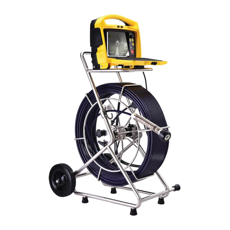
Vivax Metrotech vCamMX-2 Installation guide
Vivax Metrotech

Vivax Metrotech vCamMX-2 Installation guide

Vivax Metrotech vCam-6 Instruction Manual

Vivax Metrotech

Vivax Metrotech vCam-6 Instruction Manual

Vivax Metrotech vCam-6 Installation guide

Vivax Metrotech

Vivax Metrotech vCam-6 Installation guide

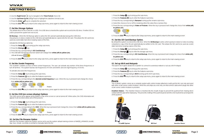
Vivax Metrotech vCamMX-2 Instruction Manual
Vivax Metrotech

Vivax Metrotech vCamMX-2 Instruction Manual

Vivax Metrotech vCamMX User manual

Vivax Metrotech

Vivax Metrotech vCamMX User manual

Vivax Metrotech vCam-5 User manual

Vivax Metrotech

Vivax Metrotech vCam-5 User manual

Vivax Metrotech vCamMX User manual

Vivax Metrotech

Vivax Metrotech vCamMX User manual

Vivax Metrotech vCam-6 User manual

Vivax Metrotech

Vivax Metrotech vCam-6 User manual
Vivax Metrotech vLoc3-5000 Instruction Manual

Vivax Metrotech

Vivax Metrotech vLoc3-5000 Instruction Manual

Vivax Metrotech vCamDrain User manual

Vivax Metrotech

Vivax Metrotech vCamDrain User manual
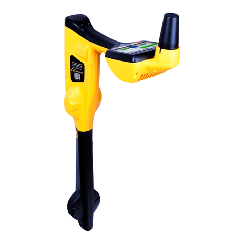
Vivax Metrotech vLoc3 RTK-Pro User manual
Vivax Metrotech

Vivax Metrotech vLoc3 RTK-Pro User manual

Vivax Metrotech i5000 User manual

Vivax Metrotech

Vivax Metrotech i5000 User manual

Vivax Metrotech WCT vCam-5 Instruction Manual
Vivax Metrotech

Vivax Metrotech WCT vCam-5 Instruction Manual

Vivax Metrotech HL 10 User manual

Vivax Metrotech

Vivax Metrotech HL 10 User manual

Vivax Metrotech vCamMX-2 User manual

Vivax Metrotech

Vivax Metrotech vCamMX-2 User manual

Vivax Metrotech vCamDrain Instruction Manual

Vivax Metrotech

Vivax Metrotech vCamDrain Instruction Manual

Vivax Metrotech vCamMX-2 User manual

Vivax Metrotech

Vivax Metrotech vCamMX-2 User manual
Vivax Metrotech vCam-6 User manual

Vivax Metrotech

Vivax Metrotech vCam-6 User manual

Popular Analytical Instrument manuals by other brands
LaserLiner LaserRange-Master T4 Pro operating instructions

LaserLiner

LaserLiner LaserRange-Master T4 Pro operating instructions

AEG Powertools AEGLDM50 Original instructions
AEG Powertools

AEG Powertools AEGLDM50 Original instructions

Powerfix Profi PEK 2.3 A1 User manual and service information
Powerfix Profi

Powerfix Profi PEK 2.3 A1 User manual and service information

SGE eVol xr user manual

SGE

SGE eVol xr user manual

Klein Tools ET510 instruction manual

Klein Tools

Klein Tools ET510 instruction manual

Sony REA-C1000 operating instructions

Sony

Sony REA-C1000 operating instructions

FLIR VS80 user manual

FLIR

FLIR VS80 user manual

iWorX iWire ROAM Wireless manual

iWorX

iWorX iWire ROAM Wireless manual

Parkside PLEM 20 A3 Operation and safety notes

Parkside

Parkside PLEM 20 A3 Operation and safety notes

PCE Americas PCE-IVE 320 manual

PCE Americas

PCE Americas PCE-IVE 320 manual

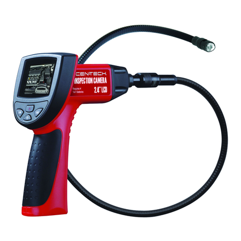
Centech 67979 Owner's manual & safety instructions

Centech

Centech 67979 Owner's manual & safety instructions

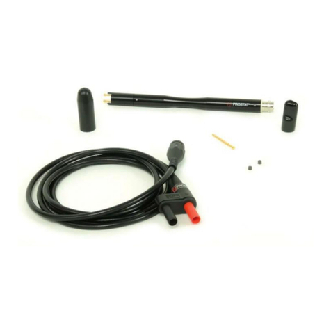
Prostat PRF-922B user manual

Prostat

Prostat PRF-922B user manual

protech QC8718 user manual

protech

protech QC8718 user manual

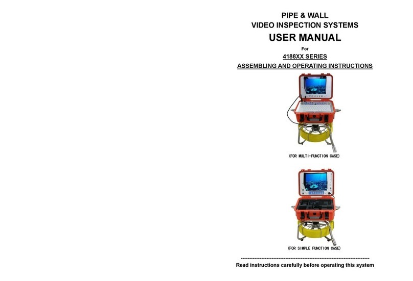
Forbest 4188 Series user manual

Forbest

Forbest 4188 Series user manual

Hathorn H12+ Operator's manual

Hathorn

Hathorn H12+ Operator's manual

Keysight E8740A-020 Startup guide

Keysight

Keysight E8740A-020 Startup guide

Ossila G2002A1 user manual

Ossila

Ossila G2002A1 user manual

Diesse VES MATIC 5 user manual

Diesse

Diesse VES MATIC 5 user manual

manuals.online logo
manuals.online logoBrands
  • About & Mission
  • Contact us
  • Privacy Policy
  • Terms and Conditions

Copyright 2025 Manuals.Online. All Rights Reserved.