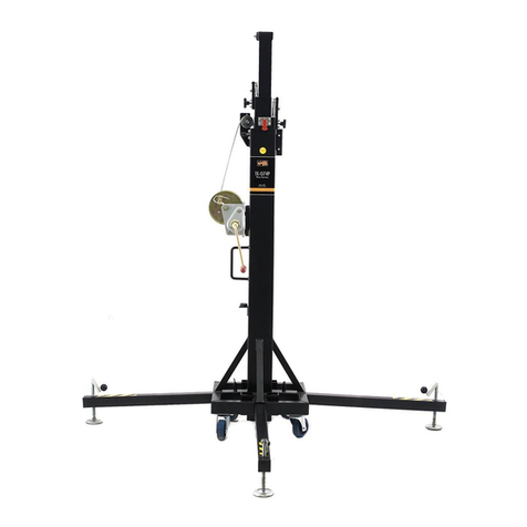
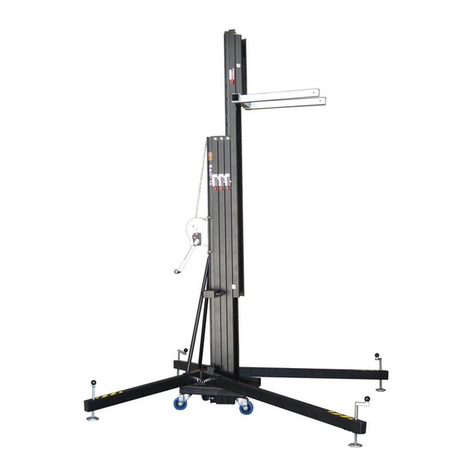
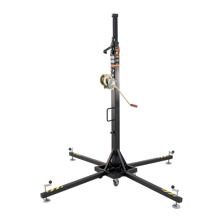
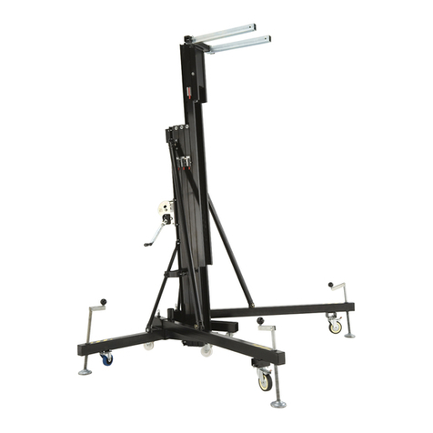
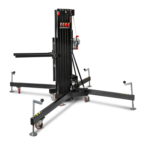
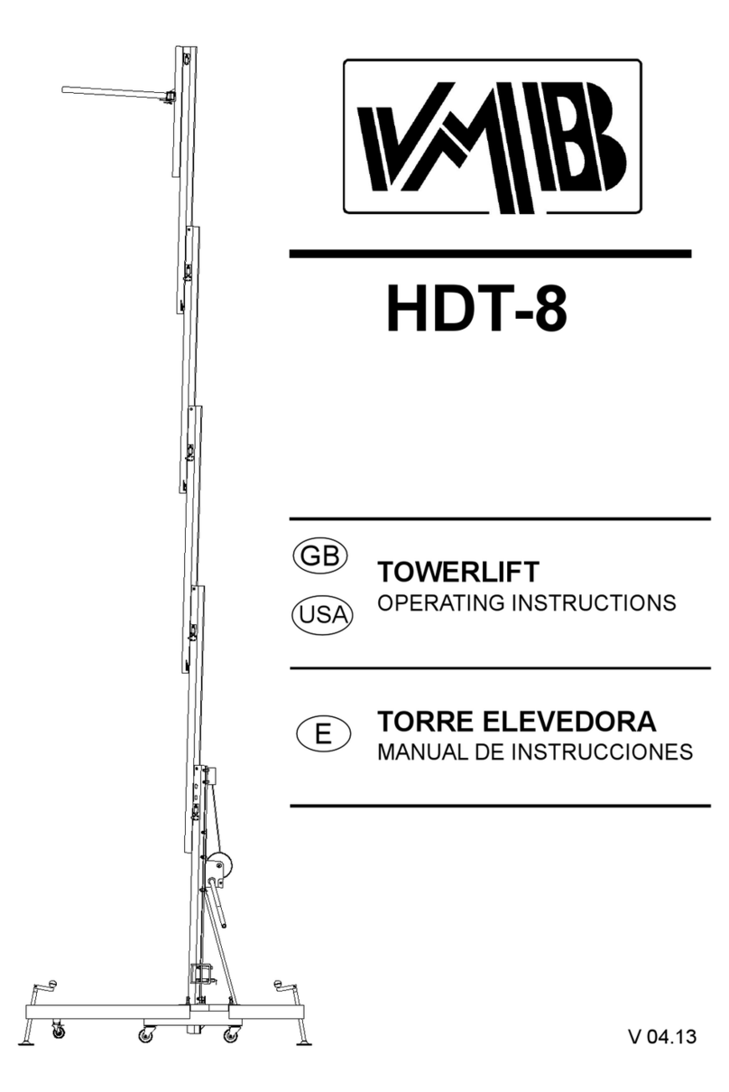
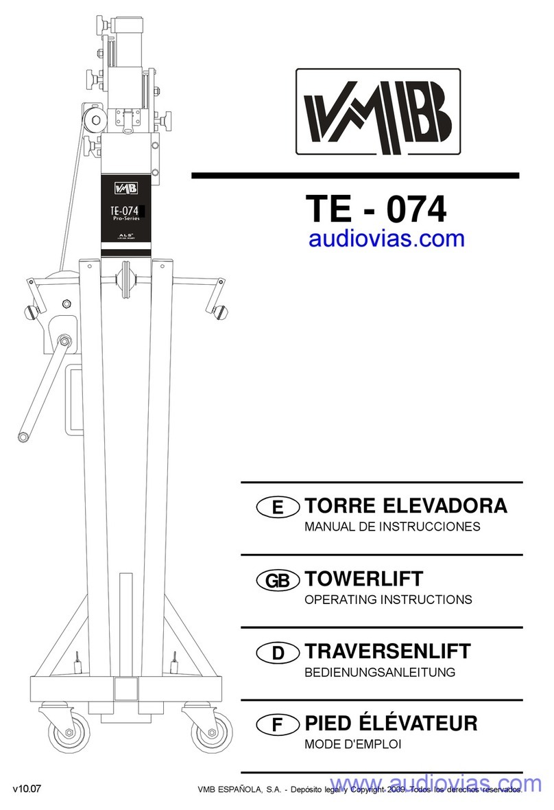
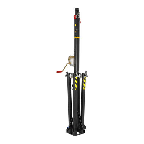
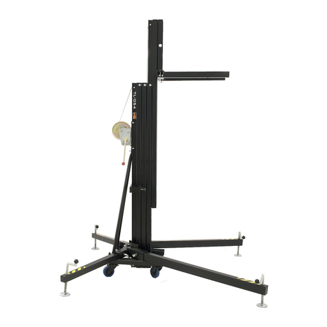
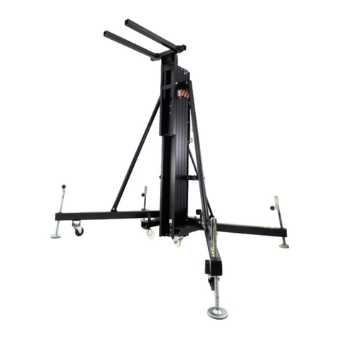
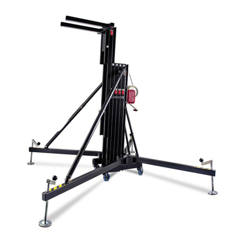
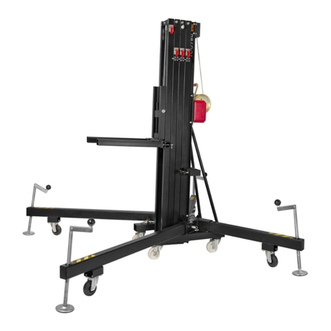
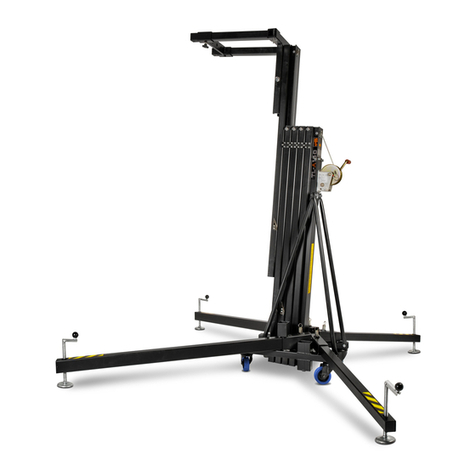
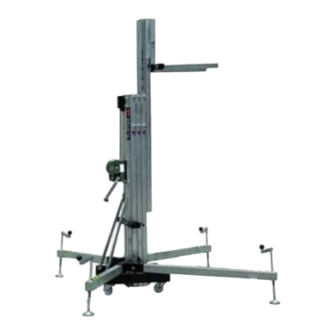
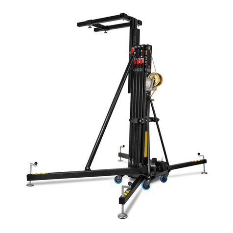
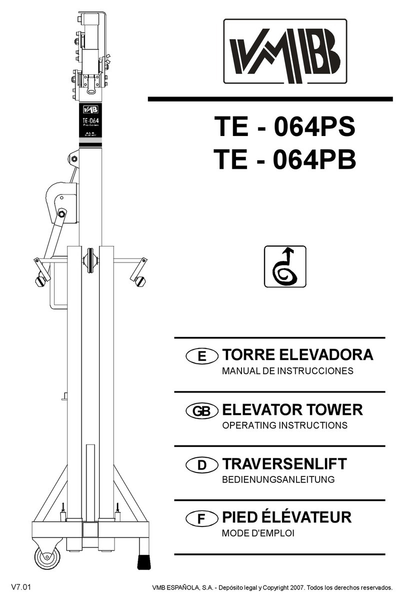
VMB TL - 075C User guide

ETORREELEVADORA
MANUALDEINSTRUCCIONES
TOWERLIFT
INSTRUCTIONS
Quick Operation Guide
GB
USA
TL -075C
TL -075CB
DTRAVERSENLIFT
BEDIENUNGSANLEITUNG
FPIEDÉLÉVATEUR
MODED'EMPLOI

Fabricante-Manufacturer-Hersteller-Fabricant
VMBEspañolaS.A.
Calle2-Pol. Ind. Picassent
E-46220 Picassent(VALENCIA)SPAIN
www.vmb.es -e-mail: contact@vmb.es
TORREELEVADORA
TOWERLIFT
TRAVERSENLIFT
PIEDÉLÉVATEUR
TL-075C
TL-075CB
Estemanualde usuarioycatálogo anexode piezasde repuestoespropiedad de VMBEspañola, S.A. Queda
prohibida sureproduccion totaloparcialporcualquiermedioque latecnologíaactualpermita.
DepósitolegalyCopyright 2006. Todoslosderechosreservados.

DepósitolegalyCopyright 2006. Todoslosderechosreservados.
VMBESPAÑOLA,S.A.
V
P
Q
H
T
R
J
S
TL-075C
ALS
C
B
F
W
N1
N2

DepósitolegalyCopyright 2006. Todoslosderechosreservados.
VMBESPAÑOLA,S.A.
Manualdeinstrucciones ESPAÑOL
CONTENIDO
1. Introducción
2.Datostécnicos
3.Normasde seguridad
4.Instruccionesde uso
5.Mantenimiento
6.Garantia
7.Certificaciones
1.INTRODUCCION
Estimadousuario,
Lea atentamenteestemanual.
Observelosdatostécnicosysiga lasnormas
deseguridadantesde utilizarlatorreelevadora.
LoselevadoresVMBson sometidosa
durísimaspruebasparagarantizarlamáxima
fiabilidad yresistencia.La torreTL-075Cestá
especialmenteconcebidaparatrabajarcon
totalfiabilidad yseguridad.Sumecanismode
elevación incorporaelsistemade seguridad
ALS «Auto-Lock Security»exclusivode VMB.
Estemanualdeberáestardisponible
permanentementejuntoalatorreelevadora.
Encasodenecesitarpiezasderepuesto,
diríjaseasudistribuidorhabitual. Solamente
deben utilizarsepiezasderepuestooriginales.
Elusuarioperderátodossusderechosde
garantíasiincorporacualquierrepuestoque
nosea originalorealizacualquiermodificación
en latorre.
Paracualquierconsultasobrelatorredeberá
indicarelnúmerodeserieyaño deconstrucción.
2.DATOSTECNICOS
2.1- TorreelevadoramodeloTL-075C/
TL-075CB
2.2- Diseñada paralevantarcargasdesdeel
mismosueloen sentido verticalacualquier
alturahasta6,5m.
2.3- Carga máximaelevable: 300 Kg.
2.4- Carga mínimaelevable:Puede subiro
bajarsincarga alguna.
2.5- Alturamáxima:6,50 m.
2.6- Alturamínimade carga :0,05 m.
Alturaplegada :1,98 m.
2.7- Superficiede labase: 2,2x2,2m.
2.8- Pesode transporte: 179 Kg.
2.9- Materialde construcción :Cuerpo princi-
palde cuatrotramosmáscarroelevador,en
perfildealuminioextrusionado6082-T6.Base,
patasysoportesvarios,en perfileriade acero
segúnDIN2394.Gatillosdeseguridady
poleasacanaladasen aceroST-37.
2.10 - Exclusivosistemade fijación yseguri-
dad ALS ( Auto-Lock Security),patentado por
VMB,quefijaeimposibilitalacaída delacarga
en todo momento.(Pat. Pen.200501056)
2.11 - Cabrestantede acción manualde 900
Kg/1000Kgde capacidad de carga máxima
con freno de discosautomático.
2.12 - Cable:Acerosegún DIN3060.Calidad
180 Kg/mm2resistentealatorsión.Diámetro6
mm.
2.13 - Platillosestabilizadoresajustablesen
laspatas,conapoyosantideslizantesde
caucho inyectado.
2.14 - Fijación de laspatascon gatillosde
seguridad.
2.15 - Nivelde burbujaparaajustarlaposición
verticalde latorre.
2.16 - La base,patas,tirantes,soportede
patasyportacargas,estánacabadosen
poliesternegrosatinado.La torrepuede sumi-
nistrarsecon elcuerpo principalacabado en
aluminionaturalototalmenteen negro(B).
2.17- Ruedasdireccionablesparafacilitarel
transportede latorreen posición verticaly
plegadahastasuemplazamientode trabajo.

DepósitolegalyCopyright 2006. Todoslosderechosreservados.
VMBESPAÑOLA,S.A.
Manualdeinstrucciones ESPAÑOL
3.NORMASDESEGURIDAD.
3.1- ElelevadorTL-075Cesuna máquina
diseñada paralaelevación de cargasen
sentido vertical,NUNCAsedebe utilizar
comoplataformaelevadorade personas.
3.2- Colocarelelevadorsóloensuperficies
durasyplanas,verificando que estáen
posiciónvertical,medianteelnivelde
burbuja(F)situado en eltramobase.
Ajustarsifueranecesarioconlosplatillos
deapoyo(Q), girando lamanivela(H)en
elsentidoadecuado.Nuncautilicecuñas
nielementosextrañosparaequilibrarel
elevador.
3.5- Nosedebe sobrepasarlacapacidad
decarga máximaindicada en laetiqueta
de característicasdelelevadoryeneste
manualde instrucciones.
3.4- Nuncasedebe elevaruna carga
sinantesverificarque estácorrectamente
apoyada ycentrada en lossoportes
elevadoresadecuados,de formaque el
pesode lacarga sóloactúe en sentido
vertical.
3.3- Comprobarquelaspatasestán
correctamentemontadasysujetasporsus
pasadoresretenedoresde seguridad.
!
Kgs

DepósitolegalyCopyright 2006. Todoslosderechosreservados.
VMBESPAÑOLA,S.A.
Manualdeinstrucciones ESPAÑOL
3.11 - Noutilicenuncaelelevadorsobre
ninguna superficiemóvil ovehículo.
3.6- Siexisteposibilidad de vientofuerteo
en ráfagas, coloque elelevadoren suelo
firmeyasegúrelocon laayuda de tirantes.
Nuncafijeun tirantesobreun vehículo
ocualquierotroelementoque pueda
desplazarse.
3.10 - Nodesplacenuncaelelevadorsise
encuentracon lacarga elevada.Noes
aconsejablerealizarningúntipode
movimiento,nitansiquierapequeños
ajustesde posicionamiento.
3.9- Nuncaseponga debajode lacarga ni
permitalapresenciade otraspersonasen
lazona de trabajodelelevador.
3.8- Tenga cuidado con todo tipode
salientesporencimadelelevadorcomo
cornisas,balcones,letrerosluminosos,
etc...
Esmuyimportanteevitarlapresenciade
cablespordebajodelaalturadetrabajodel
elevador.
3.7- Nouseescalerasencimadelelevador
nilasapoyeen élpararealizarningún tipo
de trabajo.

DepósitolegalyCopyright 2006. Todoslosderechosreservados.
VMBESPAÑOLA,S.A.
3.12 - Antesde utilizarelelevador,verifique
elestado delcable.Elcablenodebe
presentarroturadehilosoaplastamiento.
NUNCAusecablesdefectuososyencaso
de dudacambieelcable.Sóloutilicecable
de acerosegún DIN3060.Calidad180 Kg/
mm2resistentealatorsión.
3.16 - Paraeltransportedelelevadorhay
que bajartodoslostramos.
3.15- Noengrasenilubriqueelmecanismo
de freno delcabrestante.Losdiscosde
freno,han sido engrasadoscon una grasa
especialresistentealcalorylapresión.
Nodeben serutilizadosotrosproductos
paraevitarinfluirnegativamenteen el
funcionamientodelfreno.
3.14 - La cargamínimaparaunfunciona-
mientodelfreno sinproblemasesde
25Kg.Sinestacarga mínimaelfreno no
actuará.
3.13 - Nuncadesmontelamaniveladel
cabrestantesielelevadorestácon carga y
elevado.
3.17 - Solamentedeben utilizarsepiezas
de repuestooriginales.
Manualdeinstrucciones ESPAÑOL
ORIGINAL
-25

DepósitolegalyCopyright 2006. Todoslosderechosreservados.
VMBESPAÑOLA,S.A.
4.INSTRUCCIONESDEUSO.
4.1- Coloque latorreelevadoraapoyada
en susruedasde transporte(T)sobreuna
superficieplana yfirmeen suemplazamiento
de trabajo.
4.2- Saque laspatasde susoportepara
transporte(S)einsértelasafondo en sus
alojamientosde trabajo(V)comprobando que
quedan sujetasporlosgatillosretenedores
(R).Laspataslargasdelante,bajolacarga.
4.3- Ajustelaposición verticalde latorre
mediantelosplatillosde apoyoregulables
(Q)girando lasmanivelasde laspatas
estabilizadorasparalograrque laburbujadel
indicadorde nivel(F)quede centrada en el
círculo.
4.4- Coloquelosbrazosdecargaenposición
horizontalycoloquelospasadoresdeseguridad.
4.5- LACARGAMÁXIMAES DE300 Kg.
Nuncadebesobrecargarselatorreporencima
de sucarga máximade trabajo(300 kg).
La seguridad de trabajoeslomásimportante.
Coloque lacarga sobrelatorremedianteun
soporteadecuado según elcaso,de forma
que elpesode lacarga sóloactúe en sentido
vertical.
4.6-Colocarlacarga
Cuandoutilicebrazosdecargacoloque
SIEMPRElacarga lomáscercaposiblede la
torre.La carga máximade latorreTL-075C
disminuyeconladistanciaalcuerpodelatorre.
Véasecuadrode cargasen función de la
distanciadelcentrode aplicación de lacarga.
Manualdeinstrucciones ESPAÑOL
Colocarlaspatasinsertadasparatrabajo.
B30 cm 300 kg
C40 cm 253 kg
D50 cm 219 kg
E60 cm 193 kg
F70 cm 174 kg
G80 cm 155 kg
H90 cm 142 kg
I100cm 130 kg
Distancia delcentro
delacargaalatorre Cargamáxima
elevable

DepósitolegalyCopyright 2006. Todoslosderechosreservados.
VMBESPAÑOLA,S.A.
MUYIMPORTANTE: Cuando seutilizan dos
torresparaelevarun puente,ovariastorres
paraelevaruna estructurarectangularode
cualquierotraforma,esimposibleque varias
personasaccionen loscabrestantesyeleven
obajen lastorresexactamenteporigual.En
unmomentodeterminadocada torrepuede
estarsituada aunaalturamuydiferentede
lasdemás.
Esnecesarioque lassujecionesdela
estructurapermitanlasholgurasyarticulaciones
necesariasparaabsorberlasdiferencias
entrelaalturade cada torre.Con una fijación
rígida, siladiferenciade nivelesimportante,
lafuerzadelbrazode palancagenerado
forzarálateralmentelastorrespudiendo llegar
afrenarlasademásde deformarlapropia
estructurade truss.
SistemadeseguridadALS
La torreTL-075Cdisponedelsistemade
seguridad ALSautolock security(gatillos
rojos). ALSesun mecanismodeseguridad
patentadoyexclusivode VMB.ElsistemaALS
bloquea automáticamentelatorreencualquier
posiciónquesedeje.Cadatramoestá
asegurado porun gatillodelsistemaALSque
bloqueasudeslizamientodemanera
automáticaimpidiendo sudescenso.
4.7- Elevación:
Soltarelpasadorde bloqueo paratransporte
(B)ygirarlamainveladelcabrestanteen el
sentido de lasagujasde un relojparaelevar
unoscentímetroselcarro.Sacarlosbrazos
de carga(C)de suposición de transportey
colocarlosenlaposicióndetrabajo
asegurándoloscolocando lospasadores.
Girarde nuevolamanivelaen elmismo
sentido.La torresedesplegaráverticalmente
elevándosehastaalcanzarlaalturadeseada.
Manualdeinstrucciones ESPAÑOL
4.8- Retención:
Sueltelamaniveladelcabrestanteen
cualquiermomentoylatorresemantendráen
esaposiciónporlaacción delfreno dediscodel
cabrestante.Gireligeramenteen sentido
contrariolamanivelaparacomprobarque la
torreestábloqueadayaseguradaporel
sistemaALS.LosgatillosdelsistemaALS
bloquearán automáticamentelostramosde la
torrealaalturaalcanzada yelcabledejaráde
soportarlacarga.
4.9-Descenso:
Elevelacarga ligeramentehastaqueelgatillo
ALS(rojo)selibere.Presione elgatillorojode
seguridad ymanteniéndolopresionado,gire
lamaniveladelcabrestantehastabajar
completamenteeltramo.Proceda de la
mismamaneracon elsiguientetramo.La
carga irádescendiendotramoatramohasta
quelatorrequede completamenteplegadaa
sualturamínima.
Latorrepuededejarseen cualquierposición
intermediaque senecesitedelmismomodo
que alsubirlacarga.
Encasode que elgatilloestébloqueado porla
carga,hayquesubirligeramentelatorre
girandolamaniveladelcabrestantepara
después,una vezliberado elgatillo,irbajando
connormalidad.
4.10 -Transporte:
Pliegue latorrebajandocompletamentetodos
lostramos.Unavezplegadafijeelcarro
elevadorcon elpasadordebloqueopara
transporte(B).Desmontelaspatasliberando
losgatillosderetención ycolóquelasensu
posicióndetransporte(S).Aprietelos
tornillos(J).

DepósitolegalyCopyright 2006. Todoslosderechosreservados.
VMBESPAÑOLA,S.A.
5.MANTENIMIENTO.
5.1- Compruebeperiódicamenteelestadodel
cable.Siuncablepresentaroturadehilos
oaplastamiento,debe sersustituido
inmediatamenteporotronuevo.Noutilicela
torrecon cablesen malestado.Utilice
solamentecabledeaceroDIN3060 resistente
alatorsión.
5.2- Latorreelevadorasesuministra
completamenteengrasadadefábrica.No
obstante,serecomienda engrasarperiódica-
mente(segúneluso)lacorona dentada del
cabrestante,loscojinetesdelárbolde
accionamientoyelbuje,laroscadelamanivela
ylostramos.
ATENCION:Noengrasarnilubricarel
mecanismodelfreno.
Losdiscosdefreno hansidoengrasadosconuna
grasaespecialresistentealcalorylapresión.No
debenserutilizadosotrosproductosparaevitar
influirnegativamenteenelfuncionamientodel
freno.
5.3- LatorreelevadoraTL-075Cdebepasar
unainspeccióntécnicaanualcomomínimo,en
unserviciotécnicoautorizadoVMB,para
validarlascertificacionescomprobandoel
perfectoestadodeusode todosycadaunode
losdiferenteselementosmecánicosque
intervienenenelfuncionamientodelatorre
elevadora.
5.4- Solamentedebenutilizarsepiezasde
repuestooriginalesparagarantizaruna
continuada seguridad de uso.
Elusuariopierde todoslosderechosde
garantíasiincorporaotrosrepuestosque no
sean originalesollevaacabocualquier
modificación en elaparato.
Manualdeinstrucciones ESPAÑOL
7.CERTIFICACIONES
-
Directivademaquinas:
89/392/CE y98/37/CE
-BGVC1(GUV-VC1)/BGG 912 (GUV-G912)
6.GARANTIA.
Elperiodo de garantíade estatorreelevadora
esde dosaños,apartirde lafecha de compra.
VMBEspañola,S.A.secompromete,a
partirde estafecha yduranteelperiodo de
garantía,aeliminartodoslosfallosque
puedan aparecerproducidospordefectosde
losmaterialesode lafabricación.
Noestán incluidosen lagarantíalos
dañosproducidosporun usoindebido,
modificacionesdelproducto,manipulaciónpor
tercerososiniestronaturaloaccidental.
5.5- Parasolicitarcualquierpiezaderepuesto,
debe indicarsesunúmerode referencia,que
figuraenlashojasdedespiecedeestemanual.
ServicioAsistenciaTécnica VMB
S.A.T. enEspaña
Tel :902 34 10 34
Fax:961 22 11 77

DepósitolegalyCopyright 2006. Todoslosderechosreservados.
VMBESPAÑOLA,S.A.
Quick Operation Guide ENGLISH
CONTENTS
1. Introduction.
2. Technicalinformation.
3. Howtoplacethe load
4. Howtoload structures
5. Howtoload abridge
6. Guarantee
7. Certifications
1.INTRODUCTION
Dearcustomer,
Inordertooperatethe towerlift TL-075Cin
asafeandreliablemanner,followthe
instructionsinthisbooklet.
Beforeoperating the lift, read the instructions
carefully.
Pleasenotethe technicalinformation.
Ourproductsundergoveryrigoroustesting
understrictconditionsand theyaremonitored
continuouslyduring themanufacturing
process.
Inordertoguaranteetheliftfunctionand
safety,the originalpartsofthemanufacturer's
designmustbeused.Ifanypartsotherthan
thoseofthemanufacturerareused, orthe
productismodifiedinanyway,theuser
forfeitsallwarrantyrightstoclaim.
VMBreservestherighttomodifythe
productspecificationswithoutpriornotice.
The modeltype, production yearandse-
rialnumbermustbe quoted inanyqueries
orordersforspareparts.
2.TECHNICALIINFORMATION
2.1- Towerlift TL-075C/ TL-075CB.
2.2- Designed tolift loadsverticallyto
differentheightstosupportlightingsystems.
2.3- Maximumload :300 Kg.
2.4- Minimumload :Can be lifted withno
weight.
2.5- Maximumheight:6,5m.
2.6- Minimumheight:1,98 m.
2.7- Area of base: 2,2x2,2m.
2.8- Unitweight:179 Kg.
2.9- Construction material:Mainbodyin
extruded aluminium6082-T6profile.Baseand
legsaremade ofsteelprofileaccording toDIN
2394.Catchesand safetyrack ofST-37 steel.
2.10 - Exclusive ALS system ( Auto-Lock
Security),pat. pen.200501056.
2.11 - Winch:900/1000 Kg.ofmaximumload
withautomaticbraketostop the load.
2.12 - Cable:SteelDIN3060.Quality180 Kg/
mm2twistresistant. Cablediameter:6mm.
2.13 - Adjustablestabilizing feetwithruber
non-slipsupports.
2.14 - Safetycatchestoanchorthe legs.
2.15 - Spiritleveltoadjustthe towervertically.
2.16 - Base,legs,supports,forks arefinished
insatinpolyester. The towercan be supplied
withnaturalaluminiumfinishorblack (version
B).
2.17 - Swivelwheelstotransportthe lift when
folded.

DepósitolegalyCopyright 2006. Todoslosderechosreservados.
VMBESPAÑOLA,S.A.
Quick Operation Guide ENGLISH
3.SAFETYPRECAUTIONS.
3.1- TheTL-075Cisamachinedesignedto
elevateloadsupwardsinaverticaldirection,
NEVERshoulditbe used asaplatformto
elevatepeople.
3.2- Onlyplacethelifton hard,flatsurfaces
alwayscheckingthatitisinaverticalposition
byusingthebubblelevelindicator(F)found
on the basesection.Adjustthe outrigger
stabilisers(Q)byturningthecrankstolevel
ifnecessary.NEVERusewedgesorother
foreignobjectstobringthelifttoequilibrium.
3.5- The maximumload indicated on the
characteristics labeland the instructions
manualshouldnotbe exceeded
3.4- NEVERshouldthe lift be used to
elevateaload thathasnotbeen properly
checked.It isnecessarytoverifythatthe
load iscorrectlysupported and centred on
theappropriateliftsupportsothattheweight
ofthe load will onlyelevateinavertical
direction.
3.3- Check thatthe outriggersareplaced
and set-up correctlyusing the pinssafety
system.
Kgs
!

DepósitolegalyCopyright 2006. Todoslosderechosreservados.
VMBESPAÑOLA,S.A.
Quick Operation Guide ENGLISH
3.11 - NEVERusethelift onavehicleorany
othermobilesurface.
3.6- Ifthereisapossibilityofstrong winds
orgusts,placethe lift on the ground firmly
andsecureitwiththeuseofstraps.NEVER
attachastrap toavehicleoranyother
objectthatcan possiblybe moved.
3.10 - NEVERmovethe lift whilstitis
carrying aload.Itisnotadvisabletocarry
outanytype ofmovementeven small
positionaladjustments.
3.9- NEVERallowanyteammemberbelow
theloadoranybodyelseintheliftsoperating
zone.
3.8- Takecarewithall obstaclesabovethe
liftanditsextensionzone suchascornices,
balconies, and luminoussignboards. It is
veryimportanttoavoidthe presenceofall
typesofcablesbelowthe extended lift.
3.7- Donotusestepladderson the lift or
useitasasupportforthem.

DepósitolegalyCopyright 2006. Todoslosderechosreservados.
VMBESPAÑOLA,S.A.
3.12 - Beforeusing the lift, check the state
ofthe cable.The cableshouldnotcontain
brokenthreadsorshowanysignsof
crushed/flattenedareas.NEVERusefaulty
cables,alwayschange themifthereisany
doubt. Onlyusesteelcablesreference:
DIN3060.Quality:180KG/mm and torsion
resistant.
3.16 - All sectionsmustbe lowered during
transportation.
3.15- Donotgreaseorlubricatethewinch’s
breakingmechanism.Thebrakediskshave
been greased withaspecialheatand
pressureresistantsolution.Otherproducts
shouldnotbeusedtoavoidnegativeeffects
regarding the braking mechanism.
3.14 - Theminimumloadtoavoidproblems
regardingthebreakingmechanismis25Kg.
Withoutthisload the brakewill notwork.
3.13 - NEVERtakeapart the crankof the
winchwhen the lift iscarrying aload or
extended.
3.17- Onlyoriginalreplacementpartsshould
be used.
ORIGINAL
-25
Quick Operation Guide ENGLISH

DepósitolegalyCopyright 2006. Todoslosderechosreservados.
VMBESPAÑOLA,S.A.
Quick Operation Guide ENGLISH
4.USAGEINSTRUCTIONS.
4.1- Placethe lift on afirm,flatsurfaceinthe
area itistobe used supported itstransport
wheels(T).
4.2- Removetheoutriggersfromtheirtransport
supports(S)and fullyinsertthemintotheir
positions(V)checkingthattheyarefixedbythe
pins(R).
4.3- Adjustthe outriggerstabilisers(Q)by
turning the cranks tolevelthe lift. Ensureitisin
averticalposition byusing the bubblelevel
indicator(F)found on the basesection.The
bubbleshouldbe inthe centreofthe circle.
4.4- Placethe forkliftsinahorizontalposition
and securethemwiththe pins.
VMBrecommendsthe SU-070 Elevation Kit
and the BS-070 Elevation Kitwhichhaveboth
beenespeciallydesigned forloadingand
elevating withthe TL-075C.
4.5- THEMAXIMUMLOADIS300KG.The lift
shouldNEVERbe overloaded (over300KG).
Safetyatworkisthe mostimportantelement.
Placethe load ontothe lift using an adequate
supportaccording tothe need,usesothatthe
weightofthe load will onlyelevateinavertical
direction.
4.6-Howtoplace theload
Alwaysload asclosetothe toweraspossible.
Themaximumloaddiminishesaccordingtothe
distancefromthebodyofthe toweras
illustrated inthe diagrambelow.
B12 ‘‘ - 30 cm 660 lb- 300 kg
C16 ‘‘ - 40 cm 556.6lb- 253 kg
D20 ‘‘ - 50 cm 481.8lb- 219 kg
E24 ‘‘ - 60 cm 424.6lb- 193 kg
F28 ‘‘ - 70 cm 382.8lb- 174 kg
G32 ‘‘ - 80 cm 341 lb- 155 kg
H36 ‘‘ - 90 cm 312.4lb- 142 kg
I40 ‘‘ -100 cm 286 lb- 130 kg
Load centre’s
DISTANCE
tothelifting carriage
Maximumlifting
LOAD

DepósitolegalyCopyright 2006. Todoslosderechosreservados.
VMBESPAÑOLA,S.A.
CAUTION
When twotowersareused toelevateabridge
ormanytowerstoelevateastructureofany
type, itisalmostimpossiblethat twoormore
peopleco-ordinatethe wincheselevating or
lowering the loads,at exactlythe samepace.
Atacertainpointeachtowerwill be extended
toaheightdifferent tothat ofthe others.
Forthisreason itisnecessarythatthe
subjectionsof thestructureaccountforthisand
allowforthesedifferences.Witharigidfixation
andiftheleveldifferenceissignificant, theforce
generated fromthe handleofthe winchwill
deformthe structureand applyalateralforce
tothe liftscausing themtobreakand block.
SecuritysystemALS
TheTL-075Cincorporatesthepatented
securitysystemALS(AutomaticLockSecurity).
ThisVMBred triggersystemautomatically
blocksthetowerintheposition itisleftin.Each
section ofchainhasan ALSthatblocks the
section intheunlikelyeventofthe chain
breaking.
4.7- Elevation:
Turnthewinchcrankclockwisetoliftthe
carriage afewcentimeters.Releasethe forks
andplacethemintheworkingpositioninserting
the pins.Turnthe crankclockwiseand the
towerwill lift.
Quick Operation Guide ENGLISH
4.8- Hold:
The towercan be left inanyintermediate
position whichwouldbe necessary.Juststop
turning the handleofthe winchand leaveit.
The automaticbrakeofthe winchwill block it
and holdthe load.
4.9-Lowering:
Lift the load until the alslock becomesfree.
Press the ALSlock (RED)inand holditthere.
Then lowersection bysection.Repeatthe
aboveprocess foreachsection until all are
completelylowered.Ifthe ALSgetslocked,lift
the load slightlysothe ALSlock becomesfree
and lowerasabove.
4.10 -Transport:
Forthe transport ofthe towerisnecessaryto
foldthe machine lowering completelyall the
profiles.Oncethe towerlift isfolded itisvery
importanttoblock the lifting carriage withits
transportsupport(B).Getoutthe legsleaving
the blockade on the triggersand put themin
theirtransportlodging (S).Then press the
fasteningscrews.

DepósitolegalyCopyright 2006. Todoslosderechosreservados.
VMBESPAÑOLA,S.A.
5.MAINTENANCE.
5.1- Regularlycheck the stateofthe cable.If
the cablehasbroken threads,orifitshowsany
signsof crushed/flattened areas,it shouldbe
changedandreplacedimmediatelywithanew
one.Donotusethe lift ifthe cablesareinbad
condition.Onlyusesteelcablesreference:DIN
3060 torsion resistant.
5.2- The lift issupplied fromthe factory
completelygreased.However,itis
recommendedtoperiodicallygreaseaccording
touse,thegearing,theaxisbearings,the spiral
ofthe crank,and the sections.
REMEMBER:NEVERgrease orlubricate
thebreaking mechanism.
It isnot necessarytogreasethe brakedisks.
The brakedisks havebeen greased witha
specialheatand pressureresistantsolution.
Otherproductsshouldnotbe used toavoid
negativeeffectsregardingthe braking
mechanism.
5.3- Anexpertshouldcheck the TL-075Cat
leastonceayearaccordingtoitsusage.Consult
yourdistributor.
5.4- Onlyoriginalreplacementpartsshouldbe
used toguarantee continued safetyduring
usage.
The userlosesall guarantee rightsifhe/she
usesreplacementpartsthatarenotoriginal
orifhe/she makesanymodification tothe
apparatus.
5.5- Toorderanyreplacementparts,the
referencenumberon the replacementparts
pagesinthismanualshouldbe indicated.
Quick Operation Guide ENGLISH
7.CERTIFICATIONS
-
ECMachineryDirective
89/392/ECC and 98/37/ECC
-BGVC1(GUV-VC1)/BGG 912 (GUV-G912)
6.GUARANTEE.
If the during the guarantee period becauseof
poorworkmanshiporfaultymaterialsVMB
Española,S.A.will repairorreplaceit.
The guarantee period forEurope isat 2
years.
The guarantee doesnotcoverdamage
causedbyimproperuse,wearandtear
unauthorised repairs.The guarantee doesnot
coverconsumablesordefectsthathaveonlya
negligibleeffectonthe valueoroperationofthe
elevatortower.

DepósitolegalyCopyright 2006. Todoslosderechosreservados.
VMBESPAÑOLA,S.A.
Bedienungsanleitung DEUTSCH
Inhaltsverzeichnis
1.Einführung.
2.Technische Daten.
3.Sicherheitsmaßnahmen.
4.Bedienungsanleitung.
5.Wartung.
6. Garantie.
7.Zertifikat.
1.Einführung.
SehrgeehrteDamen und Herren,
dievorliegende Betriebsanleitung wurde mit
demZweck erstellt, eine zuverlässige
BedienungdesTL-075CHebeturmszu
ermöglichen.LesenSiebittedie
Betriebsanleitung vorderInbetriebnahme
sorgfältigdurch.
BittebeachtenSieauchdietechnische Daten.
UnsereProdukteunterliegenstrengsten
Prüfungen und Kontrollen beiderFertigung.
Essind ausschließlichOriginal-Ersatzteilezu
verwenden.Fürden Anwenderwerden alle
Gewährleistungsansprücheaufgehoben,wenn
erNicht-Original-Ersatzeileverwendetbzw.
Änderungen amProduktselbstvormimmt.
2.Technischedaten.
2.1- Hebeturm,TypTL-075C/ TL-075CB.
2.2- DasGerätistzumsenkrechtenHebenvon
Lasten,wieBeleuchtungskörperaufverschiede
Höhen,konzipiertworden.
2.3- Zulässige Hubkraft: 300 kg.
2.4- Mindesthublast:25 Kgs.
2.5- Zulässige Hubhöhe :6,5m.
2.6- Mindesthöhe :1,98 m.
2.7- Grundplattenfläche : 2,2x2,2m.
2.8- Transportgewicht: 179 Kgs.
2.9- Werkstoffe:Aluminium6082-T6Profil.
Basisplatteund AuslegerausStahlprofil DIN
2349.VerschlüsseausST-37 Stahl.
2.10 - ExklusiveALSSystem
(pat, pen,200501056 )
2.11 - DieWinde:900/1000 kg.
2.12 - Seildurchmesser:SteelDIN3060.
Qualität180 kg/mm 2
Durchmesser:6mm
2.13 -Auslegermitverstellbaren Spindelnund
rutschfestenGummifüßen.
2.14 -Verankerung derAuslegerüber
Sicherheitsrastbolzen.
2.15 - WasserwaagezumEinstellender
senkrechten Turmlage.
2.16- KorrosionsschutzundVeredelung durch
elektrolytische Cadmierung oder(Version B)
Satinpolyester.ErhältlichinNaturAluminium
oder.
2.17- TransportrollenzumBewegendesTurms
beisenkrechterundeingefahrenerStellungzur
Arbeitsstelle.
(optionalTL–072)

DepósitolegalyCopyright 2006. Todoslosderechosreservados.
VMBESPAÑOLA,S.A.
3.SICHERHEITSMAßNAHMEN. !
3.1 - DerTL–075Cwurde konzipiertzum
Heben und Senken von vertikalen Lasten.
Nutzen SieIhn niemalszurBeförderung
von Personen.
3.2- AchtenSiedarauf,dasderTL–Tower
auffestem,geraden Untergrundsteht. Und
vergewissernSiesichmitHilfeder
Wasserwaage (F),dass ereine vertikale
PositionzumBodeneingenommenhat.Bei
BedarfmittelsdesStelltellers(Q)durch
DrehenderSpindelkurbel(H)die
entsprechende Tunlage einstellen.
3.5- Diezulässige Höchstlast, dieSieauf
den Typenschild,welche sieinder
Bedienungsanleitung finden,darfniemals
überschritten werden
3.4- Niemalssollten Sieeineungesicherte
Ladungheben.VergewissernSiesich
immer,dasdieLadung zentriertaufder
GabelaufliegtundnurinvertikalerRichtung
hebt!
3.3- VergewissernSiesich,dass die
Auslegerrichtigeingestecktsindundnutzen
SiedieRastbolzen zumfeststellen!
Bedienungsanleitung DEUTSCH
Kgs

DepósitolegalyCopyright 2006. Todoslosderechosreservados.
VMBESPAÑOLA,S.A.
3.11 - Esistnichtgestattetden Lift auf
einemFahrzeugmiteinenmobilenUnterbau
zuinstallieren!
3.6- BeiFreiluftanwendungen den Turm
auffestenBodenstellenundmittels
Seilankergegen Windbelastung sichern.
NiemalsanFahrzeugendieAbspannungen
befestigen oderanGegenständen,die
ausweichen könnten.
3.10 - Bewegen Sieden Lift niemalsunter
Belastung.
3.8- Achten SieaufalleGegenstände im
oberen HubbereichdesLiftes.Achten Sie
aufBalkone,Leuchtschriftenundbesonders
aufstromführende Kabel.
3.7- Stellen SieniemalsLeiternan den
Tower.
Bedienungsanleitung DEUTSCH
3.9- Halten Siesichniemalswährend des
Hebensund SenkensinGefahrenbereich
auf.
This manual suits for next models
1
Table of contents
Languages:
Other VMB Lifting System manuals
Popular Lifting System manuals by other brands
stellar labs
stellar labs ECCR owner's manual

Omer
Omer VEGA 450/99-CB-4-N user manual
BraunAbility
BraunAbility 02 Series Service manual

Extreme Max
Extreme Max Boat Lift Boss installation instructions

Omega Lift
Omega Lift 43000 Operating instructions & parts manual
Bayne
Bayne Thinline GRL 1110 Operation and parts manual
