VMB TL-A150 User manual

v12.03 - Depósito legal y Copyright 2012. Todos los derechos reservados.
PROLIFTSS.L.
ETORRE ELEVADORA
MANUAL DE INSTRUCCIONES
TOWERLIFT
INSTRUCTIONS
Quick Operation Guide
GB
USA
TL - A150
DTRAVERSENLIFT
BEDIENUNGSANLEITUNG
FPIED ÉLÉVATEUR
MODE D'EMPLOI

v12.03 - Depósito legal y Copyright 2012. Todos los derechos reservados.
PROLIFTSS.L.
Fabricante - Manufacturer - Hersteller - Fabricant
PRO LIFTS S.L.
Calle 7 final - Pol. Ind. Picassent
E-46220 Picassent (VALENCIA) SPAIN
www.prolifts.es -e-mail: info@prolifts.es
TORRE ELEVADORA
TOWERLIFT
TRAVERSENLIFT
PIED ÉLÉVATEUR
TL-A150
Este manual de usuario y catálogo anexo de piezas de repuesto es propiedad de PRO LIFTS S.L. Queda
prohibida su reproduccion total o parcial por cualquier medio que la tecnología actual permita.
Depósito legal y Copyright 2012. Todos los derechos reservados.

v12.03 - Depósito legal y Copyright 2012. Todos los derechos reservados.
PROLIFTSS.L.
V
P
Q
H
T
R
C
F
N2
W
N1
TL-A150
S

v12.03 - Depósito legal y Copyright 2012. Todos los derechos reservados.
PROLIFTSS.L.
Manual de instrucciones ESPAÑOL
CONTENIDO
1. Introducción
2. Datos técnicos
3. Normas de seguridad
4. Instrucciones de uso
5. Mantenimiento
6. Garantia
7. Certificaciones
1. INTRODUCCIÓN
Estimadousuario,
Lea atentamente este manual.
Observe los datos técnicos y siga las normas
deseguridadantesdeutilizarlatorreelevadora.
Los elevadores VMB son sometidos a durísimas
pruebasparagarantizarlamáximafiabilidadyresis-
tencia. La torre TL-A150 está especialmente
concebidaparatrabajarcontotalfiabilidadyseguri-
dad.Sumecanismodeelevaciónincorporaelsiste-
madeseguridadILS«InertiaLockSecurity»deVMB.
Este manual deberá estar disponible
permanentemente junto a la torre elevadora.
En caso de necesitar piezas de repuesto,
diríjase a su distribuidor habitual. Solamente
deben utilizarsepiezasderepuesto originales.
El usuario perderá todos sus derechos de
garantía si incorpora cualquier repuesto que
noseaoriginalorealizacualquiermodificación
en la torre.
Para cualquier consulta sobre la torre deberá
indicarelnúmerodeserieyañodeconstrucción.
2. DATOS TÉCNICOS
2.1 - Torre elevadora modelo TL-A150.
2.2-Diseñadaparalevantarcargasdesdeel
mismo suelo en sentido vertical a cualquier
altura hasta 5,30 m .
2.3 - Carga máxima elevable : 150 Kg.
2.4 - Carga mínima elevable : Puede subir o
bajar sin carga alguna.
2.5 - Altura máxima: 5,30m.
2.6 - Altura mínima de carga : 0,05 m.
Altura plegada: 1,54 m.
2.7 - Superficie de la base : 1.7 x 1.85 m.
2.8 - Peso de transporte : 100 Kg.
2.9 - Materialdeconstrucción:Cuerpoprincipal
y carro elevador, en perfil de aluminio
extrusionado6082-T6.Base, patasysoportes
varios,en perfileriade acerosegúnDIN2394.
Gatillos de seguridad ypoleas acanaladas en
acero ST-37.
2.10 - SistemadeseguridadILS(InertiaLock
Security),queimposibilitalacaídadelacarga
entodomomento.
2.11-Cabrestantedeacciónmanualde450Kg
de capacidad de carga máxima con freno de
discosautomático.
2.12 - Cable : Acero según DIN3060. Calidad
180Kg/mm2resistentealatorsión.Diámetro 5
mm.
2.13 - Platillos estabilizadores ajustables en las
patas, con apoyos antideslizantes de caucho
inyectado.
2.14 - Fijación de las patas con gatillos de
seguridad.
2.15- Niveldeburbujaparaajustarlaposición
vertical de la torre.
2.16 - La base, patas, tirantes y portacargas
están acabados en poliester negro satinado. La
torrepuedesuministrarseconelcuerpoprincipal
enaluminionaturaloennegro(B).
2.17 - Ruedas direccionables para facilitar
el transporte de la torre en posición vertical
y plegada hasta su emplazamiento de tra-
bajo.

v12.03 - Depósito legal y Copyright 2012. Todos los derechos reservados.
PROLIFTSS.L.
Manual de instrucciones ESPAÑOL
3. NORMAS DE SEGURIDAD.
3.1 - El elevador TL-A150es una máquina
diseñada para la elevación de cargas en
sentido vertical, NUNCA se debe utilizar
como plataforma elevadora de personas.
3.2- Colocarelelevadorsóloensuperficies
duras y planas, verificando que está en
posición vertical, medianteel nivel de bur-
buja(F)situadoeneltramobase.Ajustarsi
fuera necesario con los platillos de apoyo
(Q), girando la manivela (H) en el sentido
adecuado. Nunca utilice cuñas ni elemen-
tos extraños para equilibrar el elevador.
3.5 - No se debe sobrepasar la capacidad
decargamáximaindicadaenlaetiquetade
características del elevador y en este ma-
nual de instrucciones.
3.4 - Nunca se debe elevar una carga sin
antes verificar que está correctamente
apoyadaycentradaenlossoporteseleva-
doresadecuados,deformaqueel pesode
la carga sólo actúe en sentido vertical.
3.3 - Comprobar que las patas están co-
rrectamente montadas y sujetas por sus
pasadoresretenedores de seguridad.
!
Kgs

v12.03 - Depósito legal y Copyright 2012. Todos los derechos reservados.
PROLIFTSS.L.
Manual de instrucciones ESPAÑOL
3.11 - No utilice nunca el elevador sobre
ninguna superficie móvil o vehículo.
3.6-Siexisteposibilidaddevientofuerteo
en ráfagas, coloque el elevador en suelo
firmeyasegúrelocon laayudadetirantes.
Nunca fije un tirante sobre un vehículo o
cualquierotroelementoquepuedadespla-
zarse.
3.10 - Nodesplacenuncael elevadorsi se
encuentra con la carga elevada. No es
aconsejable realizar ningún tipo de movi-
miento,nitansiquierapequeñosajustesde
posicionamiento.
3.9- Nuncasepongadebajodelacargani
permitalapresenciade otraspersonas en
la zona de trabajo del elevador.
3.8-Tengacuidadocontodotipodesalien-
tes por encima del elevador como corni-
sas, balcones, letreros luminosos, etc...
Es muy importante evitar la presencia de
cablespordebajodelaalturadetrabajodel
elevador.
3.7-Nouseescalerasencimadelelevador
nilasapoyeen él para realizarningún tipo
de trabajo.

v12.03 - Depósito legal y Copyright 2012. Todos los derechos reservados.
PROLIFTSS.L.
3.12 - Antes de utilizar el elevador, verifi-
que el estado del cable. El cable no debe
presentar rotura de hilos o aplastamiento.
NUNCA usecablesdefectuososyencaso
dedudacambieelcable.Sóloutilicecable
de acerosegúnDIN3060.Calidad180Kg/
mm2resistente a la torsión.
3.16 - Para el transporte del elevador hay
que bajar todos los tramos.
3.15-Noengrasenilubriqueelmecanismo
de freno del cabrestante. Los discos de
freno,han sidoengrasados conuna grasa
especialresistentealcalorylapresión.No
deben ser utilizados otros productos para
evitarinfluirnegativamenteenelfunciona-
miento del freno.
3.14 - La carga mínima para un funciona-
mientodelfrenosinproblemasesde25Kg.
Sin estacarga mínima el frenono actuará.
3.13 - Nunca desmonte la manivela del
cabrestantesielelevadorestáconcargay
elevado.
3.17 - Solamente deben utilizarse piezas
derepuesto originales.
Manual de instrucciones ESPAÑOL
ORIGINAL
-25

v12.03 - Depósito legal y Copyright 2012. Todos los derechos reservados.
PROLIFTSS.L.
4. INSTRUCCIONES DE USO.
4.1 - Coloque la torre elevadora apoyada en
susruedasdetransporte(T)sobreunasuper-
ficie plana y firme en su emplazamiento de
trabajo.
4.2-Saquelaspatasdesusoporteparatrans-
porte(S)einsértelasafondoensusalojamien-
tos de trabajo (V) comprobando que quedan
sujetas por los gatillos retenedores (R). Las
pataslargasdelante,bajolacarga.
4.3 - Ajuste la posición vertical de la torre me-
diante los platillos de apoyo regulables (Q)
girandolasmanivelasdelaspatasestabiliza-
dorasparalograrquelaburbujadelindicador
denivel(F)quedecentradaenelcírculo.
4.4 - Coloquelosbrazosdecargaen posición
horizontal y coloque los pasadores de seguri-
dad.
4.5 - RESPETARLACARGAMÁXIMA.
Nuncadebesobrecargarselatorreporencima
de su carga máxima de trabajo 150 Kg .
Laseguridadde trabajoeslomásimportante.
Coloque la carga sobre la torre mediante un
soporteadecuadosegúnelcaso,deformaque
elpesodelacargasóloactúeensentidoverti-
cal.
4.6 - Colocar la carga
Cuando utilice brazos de carga coloque
SIEMPRE la carga lo más cerca posible de la
torre. La carga máxima de la torre disminuye
con la distancia al cuerpo de la torre. Véase
cuadrodecargasenfuncióndeladistanciadel
centro deaplicacióndela carga.
Manual de instrucciones ESPAÑOL
A 25 cm
B 30 cm
C 40 cm
D 50 cm
E 60 cm
Distancia del centro
de la carga a la torre TL-A150
150 Kg
135 Kg
112 Kg
96 Kg
84 Kg
Cargamáximaelevable

v12.03 - Depósito legal y Copyright 2012. Todos los derechos reservados.
PROLIFTSS.L.
MUY IMPORTANTE: Cuando se utilizan dos
torres para elevar un puente, o varias torres
para elevar cualquier tipo de estructura, es
imposible que varias personas accionen los
cabrestantes yelevenobajenlastorres exac-
tamente por igual. En un momento determi-
nado cada torre puede estar situada a una
altura muy diferente de las demás.
Es necesario que las sujeciones dela estruc-
turapermitanlasholgurasyarticulacionesne-
cesarias para absorber las diferencias entre
la altura de cada torre. Con una fijación rígi-
da, si la diferencia de nivel es importante, la
fuerza del brazo de palanca generado forza-
rá lateralmente las torres pudiendo llegar a
frenarlas además de deformar la propia es-
tructura de truss.
Sistema de seguridad ILS
La torre TL-A150 dispone del sistema de se-
guridad ILSinertia lock security.
ElsistemaILSbloqueaautomáticamentela to-
rreen cualquier posición que se dejeen caso
de roturadel cable.
4.7 - Elevación:
Girarlamaniveladelcabrestanteenelsentido
de las agujas de un reloj para elevar unos
centímetros el carro. Sacar los brazos de
carga (C) de su posición de transportey co-
locarlos en la posición de trabajo asegu-
rándoloscolocandolospasadores.
Girar denuevo la manivela en el mismosen-
tido.Latorresedesplegaráverticalmenteele-
vándosehastaalcanzarlaalturadeseada.
GraciasalsistemaSRSlograráelevarla torre
prograsivamente.
Manual de instrucciones ESPAÑOL
4.8 - Retención:
Suelte la manivela del cabrestante en cual-
quiermomentoylatorresemantendráenesa
posición por la acción del freno de disco del
cabrestante.
4.9 - Descenso:
La maniobra de descenso se consigue de
manera contraria a la elevación. Girar la ma-
nivela del cabrestante (W)ensentido contra-
rio alas agujasdel reloj(N2) descendiendo la
carga para que vayan bajando los diferentes
tramoshastaquelatorrequedecompletamen-
teplegadaasualturamínima.
La torre puede dejarse en cualquier posición
intermedia que se necesite del mismo modo
que al subir la carga.
4.10 - Transporte:
Plieguelatorrebajandocompletamentetodos
lostramos.Desmonte las patas liberando los
gatillos de retención y colóquelas en supo-
sición de transporte (S).

v12.03 - Depósito legal y Copyright 2012. Todos los derechos reservados.
PROLIFTSS.L.
5. MANTENIMIENTO.
5.1 - Compruebe periódicamente el estado
delcable.Siuncablepresentaroturadehilos
oaplastamiento,debesersustituidoinmedia-
tamenteporotronuevo.Noutilicelatorrecon
cablesenmalestado.Utilicesolamentecable
de acero DIN 3060 resistente a la torsión.
5.2- Latorreelevadorasesuministracomple-
tamenteengrasadadefábrica.Noobstante,se
recomienda engrasar periódicamente (según
el uso) la corona dentadadel cabrestante, los
cojinetesdelárboldeaccionamientoyel buje,
la rosca de la manivela y los tramos.
ATENCION: No engrasar ni lubricar el
mecanismo del freno.
Los discos de freno han sido engrasados con
unagrasaespecialresistentealcalorylapresión.
No deben ser utilizados otros productos para
evitarinfluirnegativamenteenelfuncionamiento
del freno.
5.3 - La torre elevadora TL-A150, debe pasar
unainspeccióntécnicaanualcomomínimo,en
unservicio técnicoautorizadoVMB,paravali-
darlascertificacionescomprobandoelperfec-
toestado de uso de todos y cada uno de
los diferentes elementos mecánicos que
intervienen en el funcionamiento de la torre
elevadora.
5.4 - Solamente deben utilizarse piezas de
repuesto originales para garantizar una
continuada seguridad de uso.
El usuario pierde todos los derechos de
garantía si incorpora otros repuestos que no
sean originales o lleva a cabo cualquier
modificación enel elevador.
5.5-Parasolicitarcualquierpiezaderepuesto,
debe indicarse su número de referencia, que
figura en las hojas de despiece de este
manual.
Manual de instrucciones ESPAÑOL
7. CERTIFICACIONES
-
Directiva de maquinas:
89/392/CE y98/37/CE
6. GARANTIA.
Elperiododegarantíadeestatorreelevadora
esdedosaños,apartirdelafechadecompra.
PROLIFTSS.L.secompromete,apartir
deestafechayduranteelperiododegarantía,
aeliminartodoslosfallosquepuedanapare-
cerproducidospordefectosdelosmateriales
ode la fabricación.
No están incluidos en la garantía los
daños producidos por un uso indebido,
modificacionesdelproducto,manipulaciónpor
terceros o siniestro natural o accidental.

v12.03 - Depósito legal y Copyright 2012. Todos los derechos reservados.
PROLIFTSS.L.
Quick Operation Guide ENGLISH
CONTENTS
1. Introduction.
2. Technicalinformation.
3. How to place the load
4. How to load structures
5. How to load a bridge
6. Guarantee
7. Certifications
1. INTRODUCTION
Dear customer,
In order to operate the towerlift TL-A150in
a safe and reliable manner, follow the
instructionsinthisbooklet.
Before operatingthe lift,readthe instructions
carefully.
Please note the technical information.
Our products undergo very rigorous testing
understrictconditionsandtheyaremonitored
continuously during the manufacturing
process.
In order to guarantee the lift function and
safety,theoriginalpartsofthemanufacturer's
design must be used. If any parts other than
those of the manufacturer are used, or the
product is modified in any way, the user
forfeits all warranty rights to claim.
VMB reserves the right to modify the
product specifications without priornotice.
The model type, production year and
serial number must be quoted in any
queries or orders for spare parts.
2. TECHNICAL IINFORMATION
2.1 - Towerlift TL-A150.
2.2 - Designed to lift loads vertically to
differentheightstosupportlightingsystems.
2.3 - Maximum load : 150 Kg / 331lb.
2.4 - Minimum load : Can be lifted with no
weight.
2.5 - Maximum height : 5.3 m (17.4’)
2.6 - Minimumheight : 1.54 m (5’)
2.7 - Area of base : 1.7 x 1.85 m

v12.03 - Depósito legal y Copyright 2012. Todos los derechos reservados.
PROLIFTSS.L.
Quick Operation Guide ENGLISH
3. SAFETY PRECAUTIONS.
3.1-TheTL-A150isamachinedesignedto
elevateloadsupwardsinaverticaldirection,
NEVER should it be used as a platform to
elevatepeople.
3.2- Onlyplacetheliftonhard,flatsurfaces
alwayscheckingthatitisinaverticalposition
byusingthebubblelevelindicator(F)found
on the base section. Adjust the outrigger
stabilisers(Q)byturningthecrankstolevel
if necessary. NEVER use wedges or other
foreignobjectstobringthelifttoequilibrium.
3.5 - The maximum load indicated on the
characteristics label and the instructions
manual should not be exceeded
3.4 - NEVER should the lift be used to
elevate a load that has not been properly
checked. It is necessary to verify that the
load iscorrectly supported and centred on
theappropriateliftsupportsothattheweight
of the load will only elevate in a vertical
direction.
3.3 - Check that the outriggers are placed
and set-up correctly using the pins safety
system.
Kgs
!
v12.03 - Depósito legal y Copyright 2012. Todos los derechos reservados.
PROLIFTSS.L.
Quick Operation Guide ENGLISH
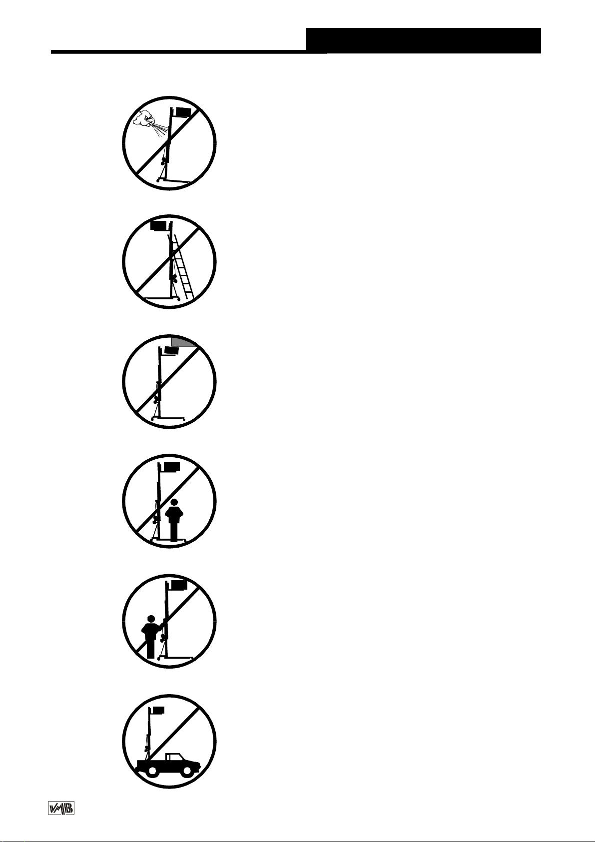
3.11-NEVERusetheliftonavehicleorany
other mobile surface.
3.6 - If there isa possibilityof strong winds
or gusts, place the lift on the ground firmly
andsecureitwiththeuseofstraps.NEVER
attach a strap to a vehicle or any other
object that can possibly be moved.
3.10 - NEVER move the lift whilst it is
carrying a load. It is not advisable to carry
out any type of movement even small
positionaladjustments.
3.9-NEVERallowanyteammemberbelow
theloadoranybodyelseintheliftsoperating
zone.
3.8-Takecarewithallobstaclesabovethe
liftanditsextensionzonesuchascornices,
balconies, and luminous signboards. It is
very important to avoid the presence of all
types of cables below the extended lift.
3.7 - Do not use stepladders on the lift or
use it as a support for them.

v12.03 - Depósito legal y Copyright 2012. Todos los derechos reservados.
PROLIFTSS.L.
3.12 - Before using the lift, check the state
of the cable. The cable should not contain
broken threads or show any signs of
crushed/flattenedareas.NEVERusefaulty
cables,alwayschange themif there isany
doubt. Only use steel cables reference:
DIN3060. Quality:180KG/mmandtorsion
resistant.
3.16 - All sections must be lowered during
transportation.
3.15-Donotgreaseorlubricatethewinch’s
breakingmechanism.Thebrakediskshave
been greased with a special heat and
pressureresistantsolution.Otherproducts
shouldnotbeusedtoavoidnegativeeffects
regarding the braking mechanism.
3.14-Theminimumloadtoavoidproblems
regardingthebreakingmechanismis25KG.
Without this load the brake will not work.
3.13 - NEVER take apart the crank of the
winch when the lift is carrying a load or
extended.
3.17-Onlyoriginalreplacementpartsshould
be used.
ORIGINAL
-25
Quick Operation Guide ENGLISH

v12.03 - Depósito legal y Copyright 2012. Todos los derechos reservados.
PROLIFTSS.L.
Quick Operation Guide ENGLISH
4. USAGE INSTRUCTIONS.
4.1 - Place thelifton a firm, flat surface in the
areaitistobe usedsupportedbyitstransport
wheels (T).
4.2-Removetheoutriggersfromtheirtransport
supports (S) and fully insert them into their
positions (V) checking that they are fixed by
the pins (R).
4.3 - Adjust the outrigger stabilisers (Q) by
turningthecranks(H)tolevelthelift.Ensureitis
in a vertical position by using the spirit level
indicator (F) found on the base section. The
bubbleshouldbeinthecentreofthecircle.
4.4-Placetheforksinahorizontalpositionand
securethemwiththepins.
4.5 - DO NOT OVERLOAD THE LIFT
TL-A150 MAXIMUM LOAD IS 150 KG.
TheliftshouldNEVERbeoverloaded. Safety
at work is the most important element. Place
theloadontotheliftusinganadequatesupport
accordingtotheneed,usesothattheweightof
theloadwillonlyelevateinaverticaldirection.
4.6 - How to place the load
Always load as close to the tower as possi-
ble.The maximum loaddiminishes according
to the distance from the body of the tower as
illustrated in the diagrambelow.
A 25 cm
B 30 cm
C 40 cm
D 50 cm
E 60 cm
Distancefrom the
center of the load to
thecarriage TL-A150
150 Kg
135 Kg
112 Kg
96 Kg
84 Kg
Maximum load

v12.03 - Depósito legal y Copyright 2012. Todos los derechos reservados.
PROLIFTSS.L.
CAUTION
Whentwo towersare usedtoelevatea bridge
or many towers to elevate a structure of any
type, it is almost impossible that two or more
people co-ordinate the winches elevating or
lowering the loads, at exactly the same pace.
Ata certain point eachtower will be extended
to a height different to that of the others.
For this reason it is necessary that the
subjections of the structure account for this
andallowforthesedifferences.Witharigidfix-
ingandifthelevel difference issignificant,the
force generated fromthe handle of the winch
will deform the structure and apply a lateral
force to the lifts causing them to break and
block.
SecuritysystemILS
The towerliftincorporates thesecurity system
ILS (Inertia Lock Security) .
Thissystem automatically blocks the tower in
caseof the cable breaking.
4.7 - Elevation:
Turn the winch crank clockwise to lift the
carriagea fewcentimeters. Releasethe forks
and place them in the working position,
inserting the pins. Turn the crank clockwise
and the tower will lift.
Quick Operation Guide ENGLISH
4.8 - Hold:
The tower can be left in any intermediate
positionnecessary.Juststopturningthe handle
ofthewinchandleaveit.Theautomatic brake
ofthewinchwillblockitandholdtheload.
4.9 - Lowering:
To bring thelift down just turn the winchin the
appropiateanticlockwisedirectiontolowerthe
carriage and all theprofiles. The sections will
lower onebyone.
4.10 - Transport:
For thetransportofthetoweritisnecessaryto
foldtheliftloweringcompletelyalltheprofiles
andplacingtheoutriggersintheirslotslocated
on the base of the lift. The lift can then be
transportedonitswheels.

v12.03 - Depósito legal y Copyright 2012. Todos los derechos reservados.
PROLIFTSS.L.
5. MAINTENANCE.
5.1 - Regularlycheckthe stateofthecable.If
thecablehasbrokenthreads,orifitshowsany
signs of crushed/flattened areas, it should be
changedandreplacedimmediatelywithanew
one. Donot use theliftifthe cablesarein bad
condition. Only use steel cables reference:
DIN 3060 torsion resistant.
5.2 - The lift is supplied from the factory
completely greased. However, it is
recommendedtoperiodicallygreaseaccording
to use, the gearing, the axis bearings, the
spiral of the crank, and the sections.
REMEMBER: NEVER grease or lubricate
the breaking mechanism.
It is not necessary to grease the brake disks.
The brake disks have been greased with a
special heat and pressure resistant solution.
Other products should not be used to avoid
negative effects regarding the braking
mechanism.
5.3 - An expert should check the Towerlift at
leastonceayearaccordingtoitsusage.Consult
yourdistributor.
5.4-Onlyoriginalreplacementpartsshouldbe
used to guarantee continued safety during
usage.
Theuserlosesallguaranteerightsifhe/sheuses
replacementpartsthatare notoriginal orif he/
shemakes anymodification tothe apparatus.
5.5 - To order any replacement parts, the
reference number on the replacement parts
pagesinthismanualshouldbeindicated.
Quick Operation Guide ENGLISH
7. CERTIFICATIONS
-
ECMachinery Directive
89/392/ECC and 98/37/ECC
6. GUARANTEE.
If theduring the guaranteeperiod because of
poor workmanship or faulty materials PRO
LIFTSS.L.willrepairorreplaceit.
The guarantee period for Europe is at 2
years.
The guarantee does not cover damage
caused by improper use, wear and tear
unauthorisedrepairs.Theguaranteedoesnot
cover consumables or defects that have only
anegligibleeffectonthevalueoroperationof
the elevator tower.

v12.03 - Depósito legal y Copyright 2012. Todos los derechos reservados.
PROLIFTSS.L.
Bedienungsanleitung DEUTSCH
Inhaltsverzeichnis
1. Einführung.
2. TechnischeDaten.
3. Sicherheitsmaßnahmen.
4. Bedienungsanleitung.
5. Wartung.
6. Garantie.
7. Zertifikat.
1. Einführung.
SehrgeehrteDamenundHerren,
die vorliegende Betriebsanleitung wurde mit
dem Zweck erstellt, eine zuverlässige
Bedienung des TL-A150 Hebeturms zu
ermöglichen. Lesen Sie bitte die
Betriebsanleitung vor der Inbetriebnahme
sorgfältigdurch.
BittebeachtenSieauchdietechnischeDaten.
Unsere Produkte unterliegen strengsten
PrüfungenundKontrollenbeiderFertigung.
EssindausschließlichOriginal-Ersatzteilezu
verwenden. Für den Anwender werden alle
Gewährleistungsansprücheaufgehoben,wenn
er Nicht-Original-Ersatzeile verwendet bzw.
ÄnderungenamProduktselbstvormimmt.
2. Technische daten.
2.1 - Hebeturm, Typ TL-A150.
2.2-DasGerätistzumsenkrechtenHebenvon
Lasten,wieBeleuchtungskörperaufverschiede
Höhen,konzipiertworden.
2.3 - Zulässige Hubkraft: 150 Kg.
2.4 - Mindesthublast : kann ohne Gewicht
ausgefahrenwerden.
2.5 - Zulässige Hubhöhe : 5,30 m.
2.6 - Mindesthöhe : 1,54 m.
2.7 - Grundplattenfläche : 1.7 x 1.85 m.
2.8 - Transportgewicht : 100 Kg .
2.9 - Werkstoffe: Aluminium 6082-T6 Profil.
Basisplatte und Ausleger aus Stahlprofil DIN
2349.VerschlüsseausST-37Stahl.
2.10-ExklusiveILSSystem.
2.11 - Die Winde: 450 kg.
2.12-Seildurchmesser:SteelDIN3060.
Qualität 180kg/ mm2
Durchmesser:6mm
2.13-AuslegermitverstellbarenSpindelnund
rutschfestenGummifüßen.
2.14 - Verankerung der Ausleger über
Sicherheitsrastbolzen.
2.15 - Wasserwaage zum Einstellen der
senkrechtenTurmlage.
2.16-Korrosionsschutz undVeredelungdurch
elektrolytische Cadmierung oder (Version B)
Satinpolyester.Erhältlich inNatur Aluminium
oder.
2.17-TransportrollenzumBewegendesTurms
beisenkrechterundeingefahrenerStellungzur
Arbeitsstelle

v12.03 - Depósito legal y Copyright 2012. Todos los derechos reservados.
PROLIFTSS.L.
3. SICHERHEITSMAßNAHMEN. !
3.1 - Der TL-A150 wurde konzipiert zum
Heben und Senken von vertikalenLasten.
NutzenSieIhnniemalszurBeförderungvon
Personen.
3.2- AchtenSiedarauf,dasderTL–Tower
auffestem,geradenUntergrundsteht.Und
vergewissern Sie sich mit Hilfe der
Wasserwaage (F), dass er eine vertikale
PositionzumBodeneingenommenhat.Bei
Bedarf mittels des Stelltellers (Q) durch
Drehen der Spindelkurbel (H) die
entsprechendeTunlageeinstellen.
3.5 - Die zulässige Höchstlast, die Sie auf
den Typenschild, welche sie in der
Bedienungsanleitung finden, darf niemals
überschrittenwerden
3.4-NiemalssolltenSieeineungesicherte
Ladung heben. Vergewissern Sie sich
immer, das die Ladung zentriert auf der
GabelaufliegtundnurinvertikalerRichtung
hebt!
3.3 - Vergewissern Sie sich, dass die
Auslegerrichtigeingestecktsindundnutzen
SiedieRastbolzenzumfeststellen!
Bedienungsanleitung DEUTSCH
Kgs

v12.03 - Depósito legal y Copyright 2012. Todos los derechos reservados.
PROLIFTSS.L.
3.11-EsistnichtgestattetdenLiftaufeinem
Fahrzeug mit einen mobilen Unterbau zu
installieren!
3.6-BeiFreiluftanwendungendenTurmauf
festenBodenstellenundmittelsSeilanker
gegenWindbelastungsichern. Niemalsan
FahrzeugendieAbspannungenbefestigen
oder an Gegenständen, die ausweichen
könnten.
3.10 - Bewegen Sie den Lift niemals unter
Belastung.
3.8 - Achten Sie auf alle Gegenstände im
oberen Hubbereich des Liftes. Achten Sie
aufBalkone,Leuchtschriftenundbesonders
aufstromführendeKabel.
3.7 - Stellen Sie niemals Leitern an den
Tower.
Bedienungsanleitung DEUTSCH
3.9 - Halten Sie sich niemals während des
Hebens und Senkens in Gefahrenbereich
auf.
Other manuals for TL-A150
1
Table of contents
Languages:
Other VMB Lifting System manuals

VMB
VMB TE-074 PRO User manual

VMB
VMB TL-054 User manual

VMB
VMB TE-071 Instruction Manual

VMB
VMB TL-054 Instruction Manual

VMB
VMB TE-06 Instruction Manual

VMB
VMB TE-064 User manual

VMB
VMB HDT-8 Instruction Manual

VMB
VMB TE-074PB User manual

VMB
VMB Pro Lifts TL-063 Instruction Manual

VMB
VMB TL-A450 Instruction Manual


