VMB SMART TOWERLIFT Instruction Manual

V.04.14
OPERATING INSTRUCTIONS USER MANUAL
MANUAL DE INSTRUCCIONES
SMART
TOWERLIFT
TORRE ELEVADORA
INTELIGENTE
TOWERS

SMART TOWERLIFT
TORRE ELEVADORA INTELIGENTE
PRO LIFTS S.L.
C/ Ciudad de Barcelona Nº19
Pol.Ind. Fuente del Jarro
46988 Paterna (Valencia)
Tlf Export: +34 96 171 81 86
Tlf Nacional: 96 171 81 83
Manufacturer - Fabricante
Este manual de usuario es propiedad de PRO LIFTS S.L.
Queda prohibida su reproducción total o parcial por cualquier medio que la tecnología actual permita.
Deposito legal y copyright 2014. Todos los derechos reservados.
MADE IN SPAIN (EU)
Depósito legal y copyright 2014. Todos los derechos reservados. 3PRO LIFTS S.L.
SMART TOWERS
S
E
B
C
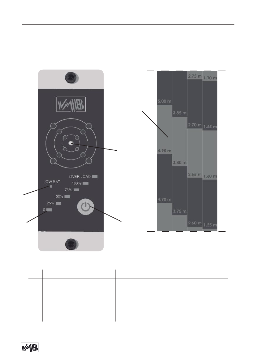
Control device /
Dispositivo de Control
English Español
SStart button Botón Inicio
EStabilization control leds Leds de control de estabilización
CWeight control load leds Leds de control del peso de la carga
BLow battery led Led de advertencia de batería baja
AHeight measurement tape Cinta métrica para medida de altura
A
Height measurement tape /
Cinta métrica medida altura
INNOVATIONS
Depósito legal y copyright 2014. Todos los derechos reservados. 4PRO LIFTS S.L.
SMART TOWERS USER MANUAL
CONTENTS
1. Introduction.
2. Technical information.
3. Operating instructions.
4. Maintenance.
5. Guarantee
1. INTRODUCTION
Dear costumer: Thank you for the pur-
chase of your new VMB SMART TOWER,
now you will have the electronic con-
trol of the stabilization, the weight of
the load the tower is carrying, and
you will be able to know how high the
load is thanks to the height measure-
ment tape attached to the side of the
towerlift.
In order to ensure a safe and reliable
operation of the SMART TOWER, plea-
se follow the instructions in this booklet
carefully. Before operating the lift,
read the instructions completely and
please note the technical information
contained within this manual.
All VMB products undergo very rigo-
rous testing, under strict conditions
and they are monitored continuously
during the manufacturing process.
In order to guarantee the lifts function
and safety, only original parts from the
manufacturer must be used. If any
parts other than those of the manu-
facturer are used, or the product is
modified in any way, the user forfeits
all warranty rights to claim. VMB re-
serves the right to modify the product
specifications without prior notice.
The model type, production year and
serial number must be quoted in any
queries or orders for spare parts.
2. TECHNICAL INFORMATION
SMART TOWER MAIN CONTROL
COMPONENTS:
- Control device
- Calibrated load cell
- Inclinometer
- Height measurement tape
- 2 repleaceble batteries AA (1.5V)
3. OPERATING INSTRUCTIONS
3.1 - START SMART DEVICE:
Before starting the device, place the
towerlift on a firm, flat surface and in-
sert the legs in their working position,
then place the forks in their working
position as well, and finally place the

Depósito legal y copyright 2014. Todos los derechos reservados. 5PRO LIFTS S.L.
SMART TOWERS USER MANUAL
load onto the lift using an adequate
support according to the need, use so
that the weight of the load will only be
elevated in a vertical direction.
Once this is done, start the SMART con-
trol device pressing the button S, all
the control leds will start flicking (If the
leds do not flick, check if the batteries
have power). If the led of the Barea is
on, replace the batteries (See point 4.
Maintenance).
The control device will turn off auto-
matically after 5 minutes.
3.2 - STABILIZATION CONTROL:
The leds of the Earea show the sta-
bilization of the towerlift. The central
green led indicates the tower is pro-
perly stabilized. The other 12 red leds
around the central led represent each
leg of the towerlift, if any of these leds
are turned on, the towerlift is not be
properly stabilized.
To fix the stabilization turn the handles
of the stabilizers, located at the end of
each leg.
3.3 - WEIGHT CONTROL OF THE LOAD:
To make the load cell work properly
the towerlift must have at least one
section without lifting and the cable
must be slack, the ALS red locks should
take the pressure off the load and re-
lease strain applied on the cable. To
do so, once the towerlift is raised at
the desired height and the last ALS
lock is locked in its corresponding hole,
slack the cable by turning the winch
crank anti-clockwise.
There are 6 red leds on the Carea,
they show the weight of the load pla-
ced on the forks, each led shows a per-
centage: 0%, 25%, 50%, 75%, 100% and
OVER LOAD. Consult the maximum
load and you will obtain the weight by
observing the red led turned on in the
SMART control device.
The lift should NEVER be overloaded.
Safety at work is the most important
issue.
3.4 - HEIGHT MEASUREMENT:
Thanks to the SRS system, unique to
VMB, our towerlift rises each section in
order, being the first section the one
that carries the forks, and so on until
all sections are at a maximum height.
With this unique feature we have been
able to incorporate a measurement
tape located at one side of the tower,
this tape allows you to always know at
what height the forks are, with a sim-
ple glance.
Depósito legal y copyright 2014. Todos los derechos reservados. 6PRO LIFTS S.L.
SMART TOWERS USER MANUAL
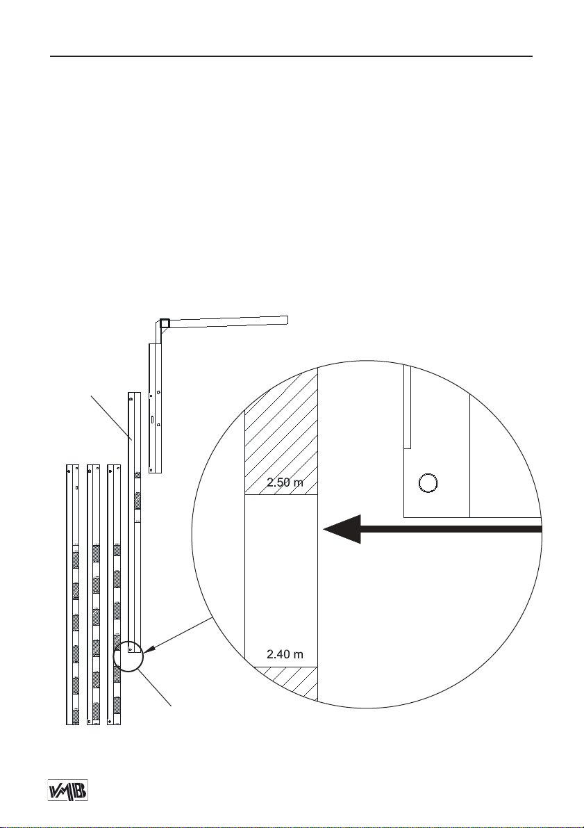
To read the height you should take as
reference the lowest part of the last
section lifted by the winch. With this
reference you should read the height
that it is shown in the tape of the next
profile.
The following image 3.4.1 show the re-
ference point and the reading of the
height measurement.
In image 3.4.1 it is shown an example
of the reading of the tower’s height.
In this example, the height is between
2.40 m and 2.50 m, we can estimate
that the height of the tower is 2.48 m
with a ± 5 cm tolerance.
TAPE PRECISION = ± 5 cm
ESTIMATION IN CENTIMETERS
The height is:
2.48 m ± 5 cm
Last elevated
section
Image 3.4.1
Lowest part
of the profile

Depósito legal y copyright 2014. Todos los derechos reservados. 7PRO LIFTS S.L.
SMART TOWERS USER MANUAL
4. MAINTENANCE
4.1 -Replacing AA Batteries (1.5V)
When the “Low Bat” led on the Barea
is turned on, the 2 AA batteries incor-
porated to make the control device
work will have lost their power. Repla-
ce them for 2 powered batteries by
untightening the screws of the control
device with an Allen key and take out
the device carefully. The batteries are
located at the back of the device.
5. GUARANTEE.
The warranty period for this device is 2
years from the date of purchase.
PRO LIFTS S.L. promises, that from the
date of purchase and during the wa-
rranty period to resolve any faults that
may occur, produced through defect
material or fabrication. Damage cau-
sed by improper use, product modi-
fication, third party manipulation or
accidental fire are not covered by this
warranty.
Depósito legal y copyright 2014. Todos los derechos reservados. 8PRO LIFTS S.L.
SMART TOWERS MANUAL DE USUARIO
CONTENIDO
1. Introducción.
2. Información técnica.
3. Instrucciones de uso.
4. Mantenimiento.
5. Garantía.
1. INTRODUCCIÓN
Estimado cliente: Gracias por la com-
pra de su Torre Elevadora Inteligente
VMB, con ella tendrá el control elec-
trónico sobre la estabilización de la
torre, el peso de la carga que sopor-
ta y podrá leer la altura a la que esta
situada la carga gracias a la banda
métrica colocada en el lateral de la
torre.
Con el fin de garantizar un funcio-
namiento seguro y fiable del Control
SMART TOWER por favor, siga cuida-
dosamente las instrucciones de este
manual.
Antes de manipular la torre elevado-
ra, lea las instrucciones completas y
tenga en cuenta la información técni-
ca contenida en este manual. Todos
los productos de VMB se someten a
pruebas muy rigurosas, en condicio-
nes estrictas y son monitorizados con-
tinuamente durante el proceso de fa-
bricación. Con el fin de garantizar el
correcto funcionamiento y seguridad
de los elevadores, sólo deben ser uti-
lizadas piezas originales del fabrican-
te. Si se utilizan piezas que no sean las
originales del fabricante, o el produc-
to se modifica de alguna manera, el
usuario pierde todos los derechos de
garantía.
VMB se reserva el derecho de modi-
ficar las especificaciones y las piezas
del producto sin previo aviso. El tipo
de modelo, año de producción y el
número de serie deben ser citadas en
cualquier consulta o pedido de piezas
de recambio.
2. INFORMACIÓN TÉCNICA
2.1 - Control Smart Tower:
Componentes:
- Dispositivo de Control
- Célula de carga
- Inclinómetro
- Cinta métrica
- 2 Pilas AA

Depósito legal y copyright 2014. Todos los derechos reservados. 9PRO LIFTS S.L.
SMART TOWERS MANUAL DE USUARIO
3. INSTRUCCIONES DE USO
3.1 -INICIAR DISPOSITIVO SMART:
Antes de iniciar el dispositivo coloque
la torre elevadora sobre una super-
ficie firme y plana e inserte las patas
correctamente en su posición de
trabajo, a continuación coloque los
brazos de carga y la propia carga en
la torre mediante un soporte adecua-
do según la necesidad, tal y como se
detalla en el manual de usuario de la
torre que corresponda.
Una vez hecho esto, inicie el disposi-
tivo de control SMART pulsando en el
botón S, los leds de control empeza-
rán a parpadear (si no lo hacen, com-
pruebe que la pila del dispositivo tiene
carga). Si el led de la zona B esta en-
cendido reemplaze la pila (Vease el
punto 4. Mantenimiento).
El dispositivo se apagará solo transcu-
rridos 5 minutos.
3.2 - CONTROL DE ESTABILIZACIÓN:
Los leds de la zona E muestran la es-
tabilización de la torre, el led central
de color verde indica que la torre esta
correctamente estabilizada. Los 12
leds rojos alrededor del led central re-
presentan cada una de las patas de
la torre, si estos estuvieran encendidos
la torre no estaría correctamente es-
tabilizada. Para corregir la estabiliza-
ción gire las manivelas de los estabi-
lizadores situados en los extremos de
las patas.
3.3 -CONTROL DE PESO DE LA CARGA:
Para que la célula de carga actue
correctamente, la torre debe tener
al menos un tramo sin elevar y el ca-
ble debe estar destensado, es decir,
la carga debe ser soportada por los
gatillos ALS rojos, para ello, una vez
alcanzada la altura y enclavado el úl-
timo gatillo correspondiente destense
el cable de acero girando la manive-
la en sentido anti-horario.
Los leds de la zona Cmuestran el peso
cargado sobre los BRAZOS DE CARGA
de la torre. Hay 6 leds de lectura de
peso, cada led muestra un porcen-
taje: 0%, 25%, 50%, 75%, 100% y SOBRE
CARGA. Consulte la carga máxima
que es capaz de levantar la torre y
obtendrá de inmediato el peso obser-
vando que led del dispositivo de con-
trol SMART está encendido.
La torre elevadora NUNCA debe ser
sobrecargada. La Seguridad en el Tra-
bajo es el elemento más importante.
3.4 - MEDIDA DE ALTURA:
Gracias al sistema SRS retentor único
de VMB Prolifts la torre eleva sus tra-
mos de forma ordenada, siendo el
primer tramo a elevarse el perfil que

Depósito legal y copyright 2014. Todos los derechos reservados. 10PRO LIFTS S.L.
SMART TOWERS MANUAL DE USUARIO
porta los brazos de carga y así con-
secutivamente hasta elevar todos sus
tramos a máxima altura.
Con esta característica única de las
torres VMB hemos sido capaces de in-
corporar una cinta métrica colocada
en el lateral de la torre que le otorga
la posibilidad de conocer en todo
momento la altura a la cual la carga
esta eleveda, con un simple golpe de
vista.
Para leer la medida de altura debe to-
mar como referencia la parte final del
último tramo que ha sido elevado por
la acción del cabestrante. Con esta
referencia deberá leer la medida que
se muestra justo en el siguiente perfil.
En la siguiente imagen 3.4.1 puede
observar el punto de referencia y la
lectura de la medida de altura:
En la imagen 3.4.1 se observa que
la lectura de la altura de la torre se
toma leyendo en la cinta métrica del
siguiente tramo, pero tomando como
referencia el final del último tramo
elevado. En el ejemplo la medida cae
entre el 2.40 m y el 2.50 m, por lo que
estimariamos que la altura a la que
esta la carga es de 2.48 m con una
tolerancia de ± 5 cm.
La altura sería:
2.48 m ± 5 cm
Último tramo
elevado Imagen 3.4.1
PRECISIÓN DE LA CINTA = ± 5 cm
CON ESTIMACIÓN DE CENTIMETROS
2.50 m
Parte final
del tramo

Depósito legal y copyright 2014. Todos los derechos reservados. 11PRO LIFTS S.L.
SMART TOWERS MANUAL DE USUARIO
4. MANTENIMIENTO
4.1 -Reemplazo de Pila AA (1.5V)
Cuando el led de “Low Bat” de la
zona B este encendido, las 2 pilas AA
(1.5V) incorporadas para el funciona-
miento del dispositivo habrán perdido
su carga. Reemplaze estas por unas
con carga, para ello, afloje los tornillos
de sujeción del dispositivo de control
con una llave Allen nº3 y extraiga el
dispositivo cuidadosamente, las pilas
están colocadas en la parte trasera
del dispositivo.
5. GARANTÍA
El período de garantía para el dispo-
sitivo SMART TOWERS es de 2 años a
partir de la fecha de compra.
PRO LIFTS S.L. se compromete, que a
partir de la fecha de compra y duran-
te el período de garantía, a resolver
los fallos que puedan producirse, de-
bidos a material defectuoso o fabri-
cación. Los daños causados por un
uso inadecuado, modificación del
producto, la manipulación de terce-
ros o incendio accidental no están cu-
biertos por esta garantía.

PRO LIFTS S.L.
C/ Ciudad de Barcelona Nº19
Pol. Ind. Fuente del Jarro
46988 Paterna (Valencia) Spain
Tlf Export: +34 96 171 81 86
Tlf Nacional: 96 171 81 83
facebook / vmblifts
Canal VMBLifts
Para más información consulte con nuestros técnicos en:
For further information follow the advise of our technicians:
Table of contents
Languages:
Other VMB Lifting System manuals


Popular Lifting System manuals by other brands


AGI
AGI M42 Assembly, Operation and Maintenance Manual

Sumner
Sumner Roust-a-Bout R Series Operator's manual

HiGH-LiFT
HiGH-LiFT YL-9FW Installation & operation manual

rav
rav VARKPH 370.32/T Translation of the original instructions

Lippert Components
Lippert Components ground control 3.0 Service manual

TBM
TBM TB1104 instruction manual

Snorkel
Snorkel MHP 13/35 Mark II Maintenance and repair parts manual

Skyjack
Skyjack SJ800-E series operating manual

Devon
Devon BLAZER 9000 Operator's manual

Snorkel
Snorkel A62JRT manual

Palfinger
Palfinger ILP 25 installation manual

Clarke
Clarke STRONG-ARM CML3 Installation, operation & maintenance instructions