VMB TL - A320 User manual
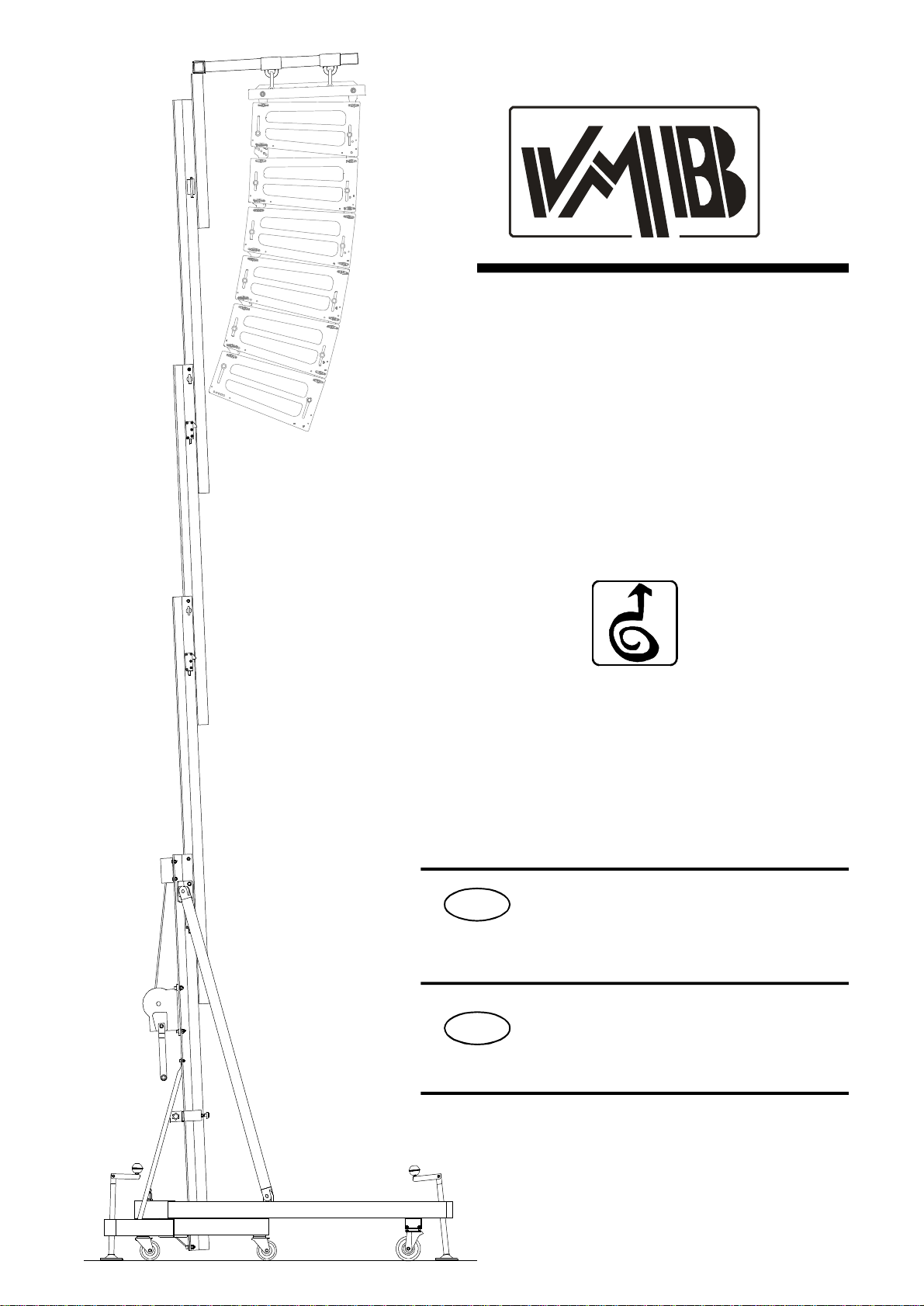
TL-A320
ETORREELEVADORA
MANUALDEINSTRUCCIONES
LINEARRAYLIFT
INSTRUCTIONMANUAL
Quick Operation Guide
GB
Fabricante-Manufacturer-Hersteller-Fabricant
VMBEspañolaS.A.
Calle2-Pol. Ind. Picassent
E-46220 Picassent(VALENCIA)SPAIN
www.vmb.es -e-mail: contact@vmb.es
TORREELEVADORA
TOWERLIFT
TRAVERSENLIFT
PIEDÉLÉVATEUR TL-A320
EstemanualdeusuarioycatálogoanexodepiezasderepuestoespropiedaddeVMBEspañola,S.A.Queda
prohibidasureproducciontotaloparcialporcualquiermedioquelatecnologíaactualpermita.
DepósitolegalyCopyright2008.Todoslosderechosreservados.

v8.05 -DepósitolegalyCopyright2008.Todoslosderechosreservados.
VMBESPAÑOLA,S.A.
TL-A320
W
N1
N2
ALS
RTS
V
P
Q
H
T
R
J
SC
B
FILS
BA
E
D
X
P1
BU

v8.05 -DepósitolegalyCopyright2008.Todoslosderechosreservados.
VMBESPAÑOLA,S.A.
CONTENTS
1. Introduction.
2. TechnicalData.
3. Security.
4. Instructions.
5. Maintenance.
6. Warranty.
7. Certifications.
1.INTRODUCTION
Thankyou forchoosing VMBTowerlifts.
Youhaveacquiredafirstclass,qualityproduct
used byprofessionalsaround the world.
Tobe abletoworkwiththistower,lifting and
flying PAand Line Array,pleasepayspecial
attention tothismanual.Pleaseobservethe
technicaldataand followall instructionsfully
foracorrectand safeuse.
Thismanualshouldalsobemadeavailableand
remainwiththe towerlift.
All VMBtowerliftsundergoastrictqualitycon-
troltoguarantee themaximumsafetyand
durability.
The TL-A320,hasbeen especiallydesigned
and engineered tohang Line Arraytoa
maximumheightof6mand aload of320kg.
Thisliftiscapableofsituating the PA50cm
fromthe bodyofthe lift.
The benefitofplacing the load atadistance
enablesthe usertoachievethe perfectcurve
and coverage forthe Line arrayflown.
The TL-A320,incorporatesthe ALS system
(Auto-Lock-Security), ILS system (Inertia-
Lock-Security)and RTS system (Retentor-
System)all exclusivetoVMBandwhich
guaranteetheloadwillnotfallandprovidecom-
pletesecurity.
ATTENTION: Donotusethistowerliftifyou
havenotreadandunderstoodtheinstructions.
2.TECHNICALIINFORMATION
2.1– Towerliftmod. TL-A320
2.2– Especiallydesigned forlifting and flying
Line arraydirectlyfromthe floortoaheightof
6m.Abletohang at50cmfromthe mainbody
ofthe lift.
2.3– Maximumload :320 Kg.at50 cmfrom
liftbody..
2.4– MinimumLoad :Can liftorlowerwithout
load.
2.5– MaximumHeight : 6m.
2.6– Folded Height:1,98 m.
2.7– BaseSurface:Diagonal2,78 x2,78 m.
2.8– TransportWeight:182 Kg.
2.9– ConstructionMaterial:6082-T6
aluminiumforthe mainbodycomprised of4
profilesandlifting carriage.DIN2394steelfor
the baseand outriggers.ST-37 steelforthe
ALSsecuritysystemand pulleys.
2.10 – SecuritySystems:ALS(Auto-Lock-
Security), ILS(Inertia-Lock-Security)which
guarantee completesecurityatall times. RTS
(Retentor-System)whichguaranteesthe
profilesliftinorder.
Duringthelifeofthistowerlift,itmayneedspare
partsformaintenance.Inthiscaseplease
contactyourdistributor.
Onlyoriginalsparepartsmustbe used.The
userlosesall rightstowarrantyifanyspare
partsotherthan originalsareused orcarries
outanymodificationoralterationtothetowerlift.
Foranyquestionsrelating tothistowerlift
pleaseindicateserialnumberandyearof
production.
QuickOperationGuide ENGLISH

v8.05 -DepósitolegalyCopyright2008.Todoslosderechosreservados.
VMBESPAÑOLA,S.A.
QuickOperationGuide ENGLISH
2.11– 1200kgManualwinchwithautomatic
disc brake.
2.12 - Cable:DIN3060 steel.180 Kg/mm2
qualityantitorsion.6mm diametre.
2.13 – Adjustablestabiliserson the outriggers
withanti-slipinjected rubberbase.
2.14 – Outriggersfixed withsecuritylocks.
2.15– Spiritleveltoadjustverticalpositioning.
2.16– Alllift elementsarefinishedinpolyester
satinblack.
2.17 – 360ºWheelsforeaseoftransportto
workplace.
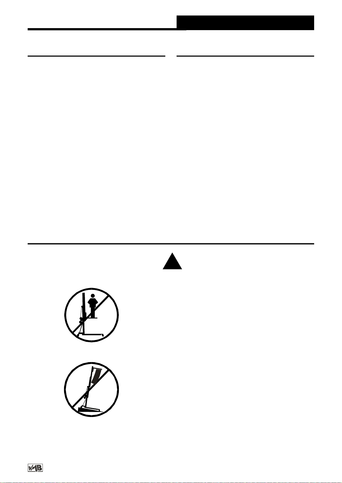
3.SAFETYPRECAUTIONS.
3.1– The TL-A320 isdesigned forlifing
Line Arrayand shouldneverbe used for
elevatingpersons.
3.2- Onlysituatetheliftonhard,flat
surfaceschecking thatitisinavertical
position withthe spiritlevel (F)included.If
necessary,adjustwithsupportstabilisers
(Q) byturning the handle (H).Donotuse
anyothermaterialstobalancethe lift.
!
3.3– Checkalloutriggersareinserted
correctlyand locked withsecuritylocks.

v8.05 -DepósitolegalyCopyright2008.Todoslosderechosreservados.
VMBESPAÑOLA,S.A.
QuickOperationGuide ENGLISH
3.5– Neverexceed the maximumweight
indicated on the towerliftand inthisma-
nual.
3.4– Neverelevatethe LineArraybefore
checking itiscorrectlyattached tothe lift.
Kgs
3.6– If thereisexcessivewind,placethe
lifton firmground and attachslingstoadd
stability.Neverattachasling toavehicle
oranyotherelementthan can move.
3.8– Becarfefulofanyhigh,obstructions
suchasbalconies,signsetc.Itisimportant
toavoidthe presenceofcablesbeneath
the working position ofthe lift.
3.7– Donotusealadderon the lift.

v8.05 -DepósitolegalyCopyright2008.Todoslosderechosreservados.
VMBESPAÑOLA,S.A.
Quick Operation Guide ENGLISH
3.11– Neverusetheliftonamobilesurface
oron anyvehicle.
3.10 – Nevertrytomovethe liftoncethe
load israised.
3.9– Neverstand belowthe raised mate-
rialand do notallowotherstostand
beneathoraround theworking area ofthe
lift.
3.12 – Beforeusingtheliftcheckthe
condition ofthe cable.The cableshould
notbe broken ortorn.NEVERusedefect
cablesand ifindoubtchange the cable.
OnlyuseDIN3060steelcable180 Kg/mm2
qualitytorsionresistantcable.
3.13 – Neverremovethe handlefromthe
winchifthe liftiselevated withload.

v8.05 -DepósitolegalyCopyright2008.Todoslosderechosreservados.
VMBESPAÑOLA,S.A.
3.16 – All profilesmustbe lowered before
the liftistransported.
3.15 – Donotgreaseorlubricatethebreak
mechanisminthe winch.The breakdiscs
havebeen especiallygreased witha
specialantiheat, pressurematerial.
Otherproductsmust notbe used soasto
avoidthe breaknotworking effectively.
3.14– Theminimumload forthe brake
functioning inthe winchis25kg.Without
thisweightthe brakewill notfunction.
3.17 – Onlyoriginalsparesmustbe used.
ORIGINAL
-25
QuickOperationGuide ENGLISH

v8.05 -DepósitolegalyCopyright2008.Todoslosderechosreservados.
VMBESPAÑOLA,S.A.
4.INSTRUCTIONS.
4.1- Situatetheliftonitstransportwheels(T)
upon aflatand stablesurface.
When erecting the liftinopen air,the risk of
wind isprevalent.
Wherewind speedsexceed 30 Km/hitis
essentialtotiethelift.2lateralfixingpoints(X)
aresituated atthe top ofprofile2,where
tensorsshouldbeattachedandfixedonsecure
andfirmground(NEVERONAVEHICULEOR
ANYTHING THATCANMOVE).
4.2– Removetheoutriggersfromtheir
transportcompartments(S)and placethemin
theworkingposition(V)ensuringtheyarefixed
withthesecuritylocks (R).Thelongoutriggers
areplacedandthe frontbeneaththeload.The
shortoutriggersareplaced atthe back.
4.3– Removethefrontsupportbars(BA)from
theirtransportcompartment(S)andplacethem
intheircorrespondingfixedposition (D)oneach
frontoutriggerand atthetop ofthe firstprofile
(E)ensuringtheyarefixedwiththe pins
provided P1.
Tocorrectlyfixthe frontsupportbars(BA),
adjustthe supportofthefrontoutriggerby
turning the stabiliserhandelinthe necessary
direction.
Insertclips(BU)and securitypins(P1).
Adjustthe verticalposition ofthe liftwiththe
stabilisers(Q)turning the handelssothatthe
spiritleveliscentred (F).
4.4– Letgo oftransportsecurity B,remove
the forks and placethemhorizontally.
Placetheliftingcarriageattherequiredheight
sothatthe LineArraybuffercan be attached.
The carefulpositioning ofthe frontoutriggers
enablestheLineArraytofitbetweenthemand
easeassembleyon tothe forks.
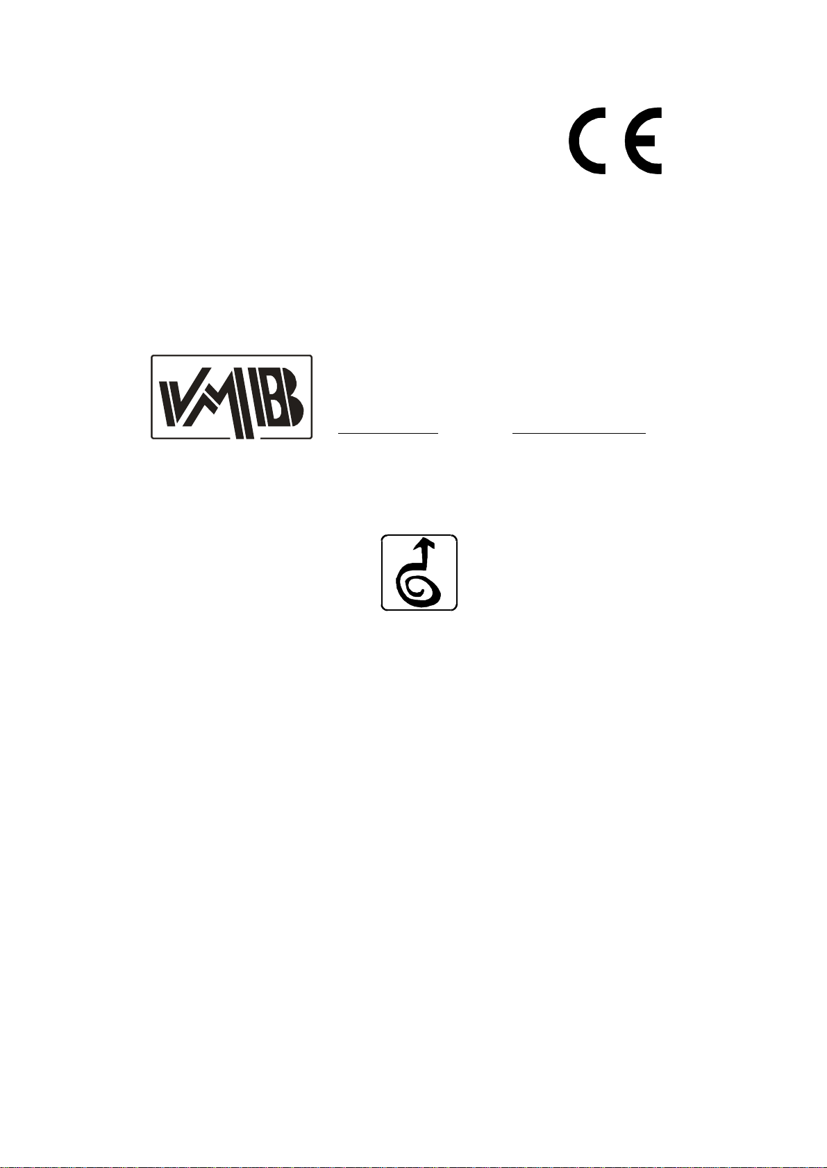
Support FAS-01 istobe fixed tothe forks by
either1or2points.See fig. 1.
If the Line ArrayBufferhas4linkpointsuse
the FAS-02 supportwhichenablesthe Line
Arraytobe flownfrom4points,see fig. 2.
BothsupportsFAS-01and FAS-02 areinserted
on the forks asfollows:
TheLineArraycabinetswillbeattachedtotheir
bufferwiththe anglescalculated according to
the acousticcoverage required.
Thisensuresthe Line Arraycabinetscan be
curvedinfunctionwiththenecessarydegrees
required between them.
Thesystemshouldbeattachedatthe
necessarydistancetoachievethe required
curve.The lastcabinetshouldnothitthe body
ofthe lift. See fig. 3.
Toensurethe maximumsecuritymarginitis
necessarrytoalways attachthe LineArrayat
the minimumdistancepossiblefromthe body
ofthelift.Thiswill meanthatthebottomcabinet
isascloseaspossibletothe bodyofthe lift.
See fig. 3A.
Toavoidoverloadingdonotseperate
uneccessarilythe LineArrayfromthe bodyof
the lift. See fig. 3B.
QuickOperationGuide ENGLISH
v8.05 -DepósitolegalyCopyright2008.Todoslosderechosreservados.
VMBESPAÑOLA,S.A.
QuickOperationGuide ENGLISH
Fig.2
Fig.1
FAS-01
FAS-02

v8.05 -DepósitolegalyCopyright2008.Todoslosderechosreservados.
VMBESPAÑOLA,S.A.
QuickOperationGuide ENGLISH
FAS-01
BC-075L
FAS-02
MR-PAS MO-30
GS-500
PAT-01
Fig.3
PR-01
MR-SPI PAS-SPI
TL-A320TL-A320
BA
v8.05 -DepósitolegalyCopyright2008.Todoslosderechosreservados.
VMBESPAÑOLA,S.A.
QuickOperationGuide ENGLISH
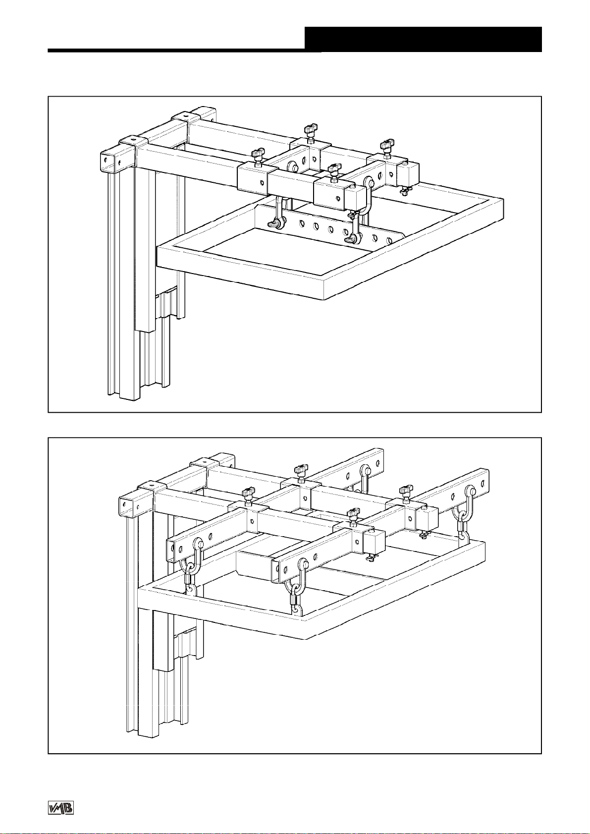
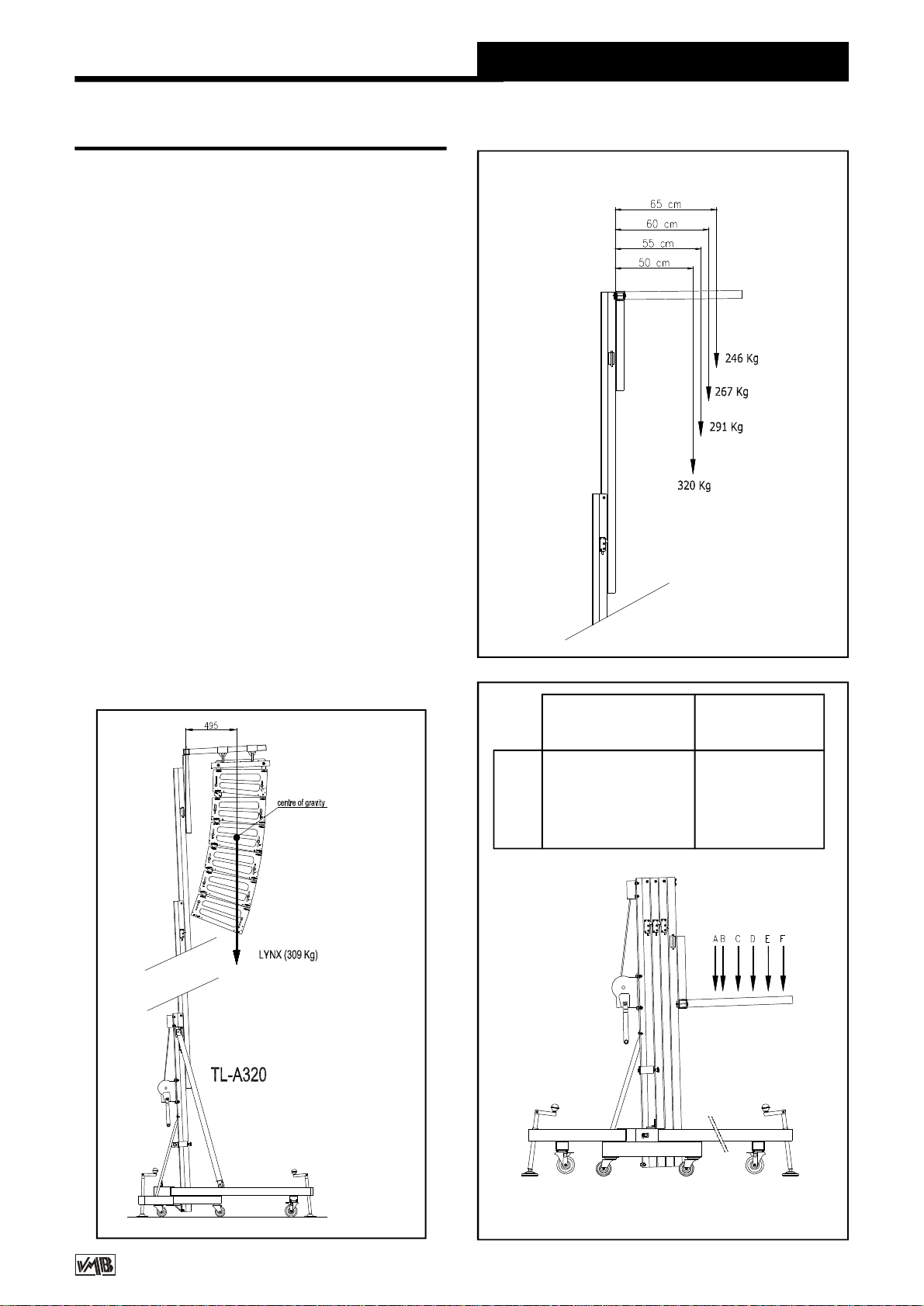
4.5- The maximumload ofthe TL-A320 is
320 Kgwiththe load pointat50 cmfromthe
lift’sbody.
Theloadingpointcapacitycanbefoundonthe
verticalline whichmarks the centreofgravity
ofthe LineArraywichistobe flow.
The situation ofthe centreofgravitydepends
upon the chosen LineArrayand isnecessary
tocalculatebeforeuse.Neverthe less,itis
usuallysituatedatthe centreoftheLineArray.
See exampleFig. 4;6LynxLX-V8cabinets
withatotalof309 Kg.
Neveroverload the liftabovethe stated
maximumweight of320 Kg.See Fig. 5.
Fig.4
Fig.5
TL-075C
B30 cm 300 kg
C40 cm 253 kg
D50 cm 219 kg
E60 cm 193 kg
F70 cm 174 kg
Centredload
DISTANCE
tothelifting carriage
Maximumlifting
LOAD
TL-A320
Fig.6
LOADSPECIFICATIONS
v8.05 -DepósitolegalyCopyright2008.Todoslosderechosreservados.
VMBESPAÑOLA,S.A.
4.6- The TL-A320, can alsobe used asa
conventionaltowerlift.
If you areusing itasaconventionaltowerlift
always placethe load asclosetothe bodyas
possible.Inall frontalload towerliftsthe
maximumloadisreducedthe furtherawayfrom
the bodythe load isplaced.
See load tableoppositeindicating distanceof
centred load foraTL-075Ctowerlift. (Fig. 6)
4.7 – Elevatingthelift:
Oncethe Line Arrayisattached toitsbuffer
and inthe desired position on the forks itis
readytobe lifted tothe required height. Turn
the winchhandleinaclockwisedirection to
elevatethe lift.
During elevation the RTS system(Retentor-
System)willensurethatthe profilesliftone by
one.
First, thelifting carriagewiththe attached Line
Arraywill raise.When ithasreached the top
then thefirstprofilewillstarttorise.Whenthis
hasreachedthetopthesecond profilewillraise
followed bythe third.
The ILSand ALSenablethe lifttoriseand
automaticallyblock the carriage and profiles
whilstrisesensuring thatitwill neverfall.The
lift,withtheLine arrayattached willremainfixed
atall times.
Oncethe systemiselevated toitsrequired
heightgentlyturnthe handleinaclockwise
direction.Thesecuritysystemswillensurethat
the load stays fixed and blocked.The redALS
locks will be blocked. Thisenablesthe cable
tobe withoutanyforceand meansitisonly
used forthe elevation and descentofthe lift.
The following instructionswill helpyou to
bring the systemdown.
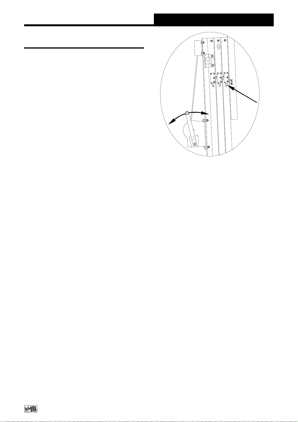
4.8 – Descendingthelift:
Tobring the liftdownyou need tofirstturnthe
winchhandleslightlyclockwiseandatthesame
timepushthe red ALSlock in(G).(Fig. 7)
Thisreleasestheblocking systems.Thenturn
the handleanticlockwise,whilstmaintaining
theALSlockpushedinuntilthe profilehasbeen
completelylowered.
AllredALSlocks shouldbe heldinonebyone
whilstthe handleisturned anticlockwiseand
the profilesarebroughtdown,one byone.If
you releaseyourfingerfromthe ALSlock it
willautomaticallyblock.Inthiscase,repeatthe
firstoperationbyturningslightlyclockwiseand
then anticlockwisewhilstalways pushing the
redALSlock in.
Itisnecessarytocompletelylowereachprofile
beforestarting tolowerthe next. If you push
anotherredALSlockwithouthaving completely
loweredthepreviousprofilethefirstprofilewill
remainblockedbythesecuritysystemandyou
will notbe abletoloweritlater.
Ifthishappens,elevatethetowerlifttothe
locked position and free the lock sothatyou
can commencethe descentagainuntil itis
completelylowered.
Finally,releasethe carriage lockfollowing the
sameprincipleasbeforeand lowerittothe
required leveltobe abletodismountthe Line
Arrayfromthe lift.
QuickOperationGuide ENGLISH
4.9- Transport
Onceall the profilesarecompletelylowered
removethe FAS-01 orFAS-02 supportandthe
forks placing themintheirhorizontalposition
facing down.Lowerthe carriage sothatright
forkcan befixedandblockedfortransport(B).
Removethefrontsupportbars( BA )bytaking
outthe pins(BU).Replacethe pinsinthe top
support ( E )of the lift’sbaseprofileand also
atthe top ofeachfrontsupportbar.
Fig.7
G

v8.05 -DepósitolegalyCopyright2008.Todoslosderechosreservados.
VMBESPAÑOLA,S.A.
5. MAINTENANCE.
5.1- Periodicallycheck the condition ofthe
cable.If acableistornorbroken itshouldbe
replaced immediately.Donotusethe liftifthe
cableisnotperfect. Onlyusetorsion resistant
steelcableDIN3060.
5.2- The liftissupplied completelygreased
fromthefactory.Nevertheless,we
recommendyou periodicallygrease(depending
on amount used)the teethof the winch(CD),
endpointofthehandle(RM),bar(EB)andthe
profilenylon drums.(Fig. 8)
ATTENTION:Donotgreaseorlubricatethe
break mechanism.
The brakediscs havebeen greasedwitha
specialheatandpressureresistantgrease.Do
notuseotherproducts.
QuickOperationGuide ENGLISH
7.CERTIFICATIONS
-
ECMachineryDirective
89/392/ECC and98/37/ECC
-BGVC1(GUV-VC1)/BGG912(GUV-G912)
6. GUARANTEE.
The warrantyperiod forthisliftis3yearsfrom
the dateofpurchase.
VMBEspañola,S.A.promises,thatfromfrom
the dateofpurchaseand during the warranty
periodtoresolveanyfaultsthatmayoccur
producedthroughdefectmaterialorfabrication.
Damagecaused byinproperuse,product
modification,terciarymanipulationoracciden-
talfirearenotcovered bythiswarranty.
5.3- Allliftsshouldundergo an annual
technicalinspectioncarriedoutbyan
authorizedVMBdealertocheckthe
certificationsand generalcondition ofall the
lift’selementsand securitysystemsinvolved
inthe lift’suse.
5.4– Onlyuseoriginalsparepartstoguarantee
acontinued securitylevel.
The userlosesallrightstowarrantyifanyspare
partsotherthan originalsareused orcarries
outanymodificationoralterationtothetowerlift.
5.5– Torequestasparepart pleaseindicate
thecorrespondingcode whichcan be foundin
thismanual.
VMBTecnicalAssistance
S.A.T. inSpain
Tel:+34 902 34 10 34
Fax:+34 961 22 1177
Fig.8
EB EB
CD RM
Placethe barsintheirtransportcompartment.
Removethe outriggers,releasingthelocks and
placeintheirtransport position (S).Turnand
tighten the fixing screws(J).The liftcan be
transported horizontallybyaddingtheRH-4kit.

v8.05 -DepósitolegalyCopyright2008.Todoslosderechosreservados.
VMBESPAÑOLA,S.A.
Manualdeinstrucciones ESPAÑOL
CONTENIDO
1.Introducción
2.Datostécnicos
3.Normasde seguridad
4.Instruccionesde uso
5.Mantenimiento
6.Garantía
7.Certificaciones
1.INTRODUCCION
Estimadousuario:
Agradecemossuconfianzaaladquirirlas
torreselevadorasVMB.
Tiene en susmanosun productode calidad
yfiabilidad contrastadasporladilatada
experienciadelosusuariosprofesionales
en todo elmundo.
Parapodertrabajarconesteelevador
volandotodotipodeequiposdesonidosin
peligroydeformasegura,leaatentamenteeste
manual,observelosdatostécnicosysiga
íntegramentetodaslasinstruccionesde
utilizaciónyseguridad.
Estemanualde instrucciones,deberáestar
disponiblepermanentementejuntoalelevador.
TodosloselevadoresVMBson sometidosa
un constantecontrolde calidad ydurísimas
pruebasdeverificación,paragarantizarla
máximafiabilidadyresistencia.
Elelevador TL-A320,ha sido proyectado
especialmenteparalevantarhasta6metros
dealtura,equiposdesonidotipolinearray
conunpesode320Kgdesplazados50cm.
enavancerespectoalcuerpodelatorre.
Estedesplazamiento,esnecesariopara
poderangularlosrecintosacústicoslos
gradosprecisosparalograrunaperfecta
coberturadesonorización.
2.DATOSTECNICOS
2.1- TorreelevadoramodeloTL-A320.
2.2- Diseñada especialmenteparalevantar
equiposde sonido tipo line arraydesde el
mismosueloen sentido verticalacualquier
alturahasta6m., con un avancerespectoal
cuerpo de latorrede 50 cm.
2.3- Cargamáximaelevable:320 Kg.despla-
zada 50 cmdelcuerpo delelevador.
2.4- Carga mínimaelevable:Puede subiro
bajarsincarga alguna.
2.5- Alturamáxima: 6m.
2.6- Alturaplegada:1,98 m.Alturamínimade
carga : 0,05 m.
2.7- Superficiede labase:Diagonales2,78
x2,78 m.
Elelevador, TL-A320,incorporalossistemas
deseguridadALS(Automatic-Lock-Security),
ILS(Inertia-Lock-Securyty)y RTS(Retentor-
System)exclusivosde VMB,que garantizan
laimposibilidad de caida de lacarga yuna
totalseguridaddeutilización.
ATENCION:
Noutiliceesteelevadorsinhaberleídoy
seguirestasinstrucciones.Encasocontrario,
podríallegaraprovocarun graveaccidente.
Durantelavidaútildelelevador,puede
necesitarpiezasderepuesto.Diríjaseen este
casoasudistribuidorhabitual.
Solamentedebenutilizarsepiezasderepuesto
originales.Elusuarioperderátodossus
derechosdegarantíasiincorporacualquier
repuestoquenoseaoriginalorealiza
cualquiermodificación enelelevador.
Paracualquierconsultasobreelelevador,
deberáindicarelnúmerode serieyaño de
construcción.
v8.05 -DepósitolegalyCopyright2008.Todoslosderechosreservados.
VMBESPAÑOLA,S.A.
2.8- Pesode transporte:182 Kg.
2.9- Materialdeconstrucción:Cuerpoprincipal
de cuatrotramosmáscarroelevador,enperfil
dealuminioextrusionado6082-T6.Base,
patasysoportesvarios,en perfileriade acero
según DIN2394.Gatillosde seguridad y
poleasacanaladasen aceroST-37.
2.10- Sistemasdefijación,seguridadALS
(Automatic-Lock-Security), ILS(Inertia-Lock-
Securyty)que fijaneimposibilitan lacaida de
lacarga en todo momentoy RTS(Retentor-
System)exclusivode VMB,que garantizala
elevación ordenada de todoslostramosdel
elevadorfiabilizando almáximosumanipula-
ción.
2.11- Cabrestantede acción manualde
1.200Kgde capacidad de carga máximacon
freno de discosautomático.
Manualdeinstrucciones ESPAÑOL
2.12 - Cable:Acerosegún DIN3060.Calidad
180 Kg/mm2antitorsión.Diámetro6mm.
2.13 - Platillosestabilizadoresajustablesenlas
patas,con apoyosantideslizantesde caucho
inyectado.
2.14- Fijacióndelaspatascongatillosde
seguridad.
2.15- Niveldeburbujaparaajustarlaposición
verticalde latorre.
2.16 – Todosloselementosdelelevador
están acabadosen poliésternegrosatinado.
2.17 - Ruedasdireccionablesparafacilitarel
transportedelatorreenposiciónverticaly
plegada hastasuemplazamientode trabajo.
3. NORMASDESEGURIDAD.
3.1- ElelevadorTL-A320esunamáquina
diseñada paralaelevación de cargasen
sentido vertical,NUNCAsedebe utilizar
comoplataformaelevadorade personas.
3.2- Colocarelelevadorsóloensuperficies
durasyplanas,verificandoqueestáen
posición vertical,medianteelnivelde
burbuja(F)situado en eltramobase.
Ajustarsifueranecesarioconlosplatillos
deapoyo(Q),girandolamanivela(H)en
elsentidoadecuado.Nuncautilicecuñas
nielementosextrañosparaequilibrarel
elevador.
!

v8.05 -DepósitolegalyCopyright2008.Todoslosderechosreservados.
VMBESPAÑOLA,S.A.
Manualdeinstrucciones ESPAÑOL
3.5- Nosedebesobrepasarlacapacidad
decargamáximaindicadaenlaetiqueta
decaracterísticasdelelevadoryeneste
manualdeinstrucciones.
3.4- Nuncasedebe elevaruna carga
sinantesverificarqueestácorrectamente
apoyada ycentrada en lossoportes
elevadoresadecuados,de formaque el
pesode lacarga sóloactúe en sentido
vertical.
3.3- Comprobarque laspatasestán
correctamentemontadasysujetasporsus
pasadoresretenedoresdeseguridad.
Kgs
3.6- Siexisteposibilidaddevientofuerteo
en ráfagas,coloque elelevadoren suelo
firmeyasegúreloconlaayudadetirantes.
Nuncafijeun tirantesobreun vehículo
ocualquierotroelementoque pueda
desplazarse.
3.7- Nouseescalerasencimadelelevador
nilasapoyeenélpararealizarningúntipo
de trabajo.

v8.05 -DepósitolegalyCopyright2008.Todoslosderechosreservados.
VMBESPAÑOLA,S.A.
Manualdeinstrucciones ESPAÑOL
3.11 - Noutilicenuncaelelevadorsobre
una superficiemóvil ovehículo.
3.10 - Nodesplacenuncaelelevadorsise
encuentracon lacarga elevada.Noes
aconsejablerealizarningún tipo de
movimiento,nitansiquierapequeños
ajustesde posicionamiento.
3.9- Nuncasepongadebajodelacargani
permitalapresenciadeotraspersonasen
lazona de trabajodelelevador.
3.8- Tengacuidadocontodotipode
salientesporencimadelelevadorcomo
cornisas,balcones,letrerosluminosos,
etc...
Esmuyimportanteevitarlapresenciade
cablespordebajodelaalturadetrabajodel
elevador.
3.12- Antesdeutilizarelelevador,verifique
elestadodelcable.Elcablenodebe
presentarroturadehilosoaplastamiento.
NUNCAusecablesdefectuososyencaso
dedudacambieelcable.Sóloutilicecable
de acerosegúnDIN3060.Calidad180Kg/
mm2resistentealatorsión.

v8.05 -DepósitolegalyCopyright2008.Todoslosderechosreservados.
VMBESPAÑOLA,S.A.
3.16 - Paraeltransportedelelevadorhay
que bajartodoslostramos.
3.15- Noengrasenilubriqueelmecanismo
de freno delcabrestante.Losdiscosde
freno,hansidoengrasadosconunagrasa
especialresistentealcalorylapresión.
Nodebenserutilizadosotrosproductos
paraevitarinfluirnegativamenteenel
funcionamientodelfreno.
3.14 - La carga mínimaparaelfunciona-
mientodelfrenodelcabrestantesinproble-
mas,esde25Kg.Sinestacargamínimael
freno podríano actuar.
3.13 - Nuncadesmontelamaniveladel
cabrestantesielelevadorestáconcargay
elevado.
3.17 - Solamentedeben utilizarsepiezas
derepuestooriginales.
Manualdeinstrucciones ESPAÑOL
ORIGINAL
-25

v8.05 -DepósitolegalyCopyright2008.Todoslosderechosreservados.
VMBESPAÑOLA,S.A.
4. INSTRUCCIONESDEUSO.
4.1- Coloque latorreelevadoraapoyada en
susruedasde transporte(T)en suemplaza-
mientodetrabajosobreunasuperficieplanay
firme.
Enelcasode montarelelevadoralairelibre,
existeelriesgo que durantesuutilización se
genereviento.
Apartirdeunavelocidaddelvientode30Km/h
esimprescindiblearriostrarelelevador,para
locualsehan previstodosargollaslaterales
defijación(X)situadasenlapartesuperiordel
segundo tramo,donde deberán fijarselos
tensoresque seránancladosalugaresfirmes
yseguros(nuncasobreunvehículoocualquier
otroelementoquepuedadesplazarse).
4.2- Saque laspatasde susoportepara
transporte(S)einsértelasafondo en sus
alojamientosde trabajo(V)comprobandoque
quedan sujetasporlosgatillosretenedores
(R).Laspataslargasdelante, bajolacarga y
lascortasdetrás.
4.3- Saquelosbrazosdeapoyofrontales(BA)
delsoportede transporte(S)ycolóquelosen
suspuntosde anclaje(D)sobrecada pata
delanteray(E)en loslateralesde laparte
superiordeltramobase,fijándoloscon los
pasadoresde seguridad P1.
Parapodercolocarcorrectamentelosbrazos
deapoyofrontales(BA),deberáajustarelapo-
yode laspatasdelanteras,girando adecua-
damentelasmanivelasdelosapoyos
regulablesde laspatas.
Colocarlosbulones(BU)ylospasadoresde
seguridad (P1).
La especialdisposición de laspatasdelante-
ras,permitesituarelequipo de sonido en el
suelojustobajolosbrazosde carga.
Sobrelosbrazosde carga,secolocarán
lossoportes FAS-01,en elcasode volarun
equipoconfijacióncentralporunoodos
puntosde vuelo,fig. 1.
Enelcasode que elsoportede volado del
equipodesonido tengacuatroanclajes
perimetrales,seutilizarán lossoportes FAS-
02 que permiten suspenderlossoportesde
volado desde cuatropuntos,verfig. 2.
Tantolossoportes FAS-01 comolos FAS-02
secolocarán sobrelosbrazosde carga en la
posiciónyformaque seindicaseguidamente:
Losrecintosacústicosdelequipo de sonido,
semontarán sobresusoportede volado con
lasangulacionescalculadasparalacobertura
acústicarequerida.
Estocondiciona que losrecintosde line array
securvarán haciadetrásen función de los
gradosnecesariosentreellos.
Elequipo deberácolocarseen consecuencia
sobrelosbrazosde carga delelevadorcon el
avancenecesarioparaconseguirque esta
curvaturapueda realizarse,sinque laparte
traserainferiordelúltimorecintotropiececon
elcuerpo delelevador.Verfig. 3.
Paraconseguirelmáximomargen de seguri-
dad,esnecesariocolocarsiempreelequipo
de sonido sobrelosbrazosde carga del
elevadorconelavancemínimoposible,de
formaque lapartetraserainferiordelúltimo
recintodelequipo line arrayseencuentrelo
máscercaposibledelcuerpo de latorre. Ver
fig. 3A.
Nosepararinnecesariamenteelequipo de
sonido delcuerpo de latorreparaevitaruna
sobrecarga.Verfig. 3B.
Manualdeinstrucciones ESPAÑOL
4.4– Soltarelsegurode transporte B ,sacar
losbrazosde carga yvolveracolocarlosen
posiciónhorizontal.
Colocarelcarroelevadoralaalturanecesaria
parapoderfijarelsoportede voladodelequipo
de line array.
Table of contents
Languages:
Other VMB Lifting System manuals

VMB
VMB TL-075 Instruction Manual

VMB
VMB TL - 075C User guide

VMB
VMB TE-074 PRO User manual

VMB
VMB TL-070 User manual

VMB
VMB TE-06 Instruction Manual

VMB
VMB Pro Lifts TL-063 Instruction Manual

VMB
VMB TE-071 Instruction Manual

VMB
VMB TL-A300 Instruction Manual

VMB
VMB TE-064 Instruction Manual

VMB
VMB TL-A150 Instruction Manual


Popular Lifting System manuals by other brands

Ronin
Ronin Lift instruction manual

FlexiModal
FlexiModal BicyLift Assembly, operation and maintenance instructions

APlusLift
APlusLift HW-10KBP Installation manual & operation instructions

LSP inc.
LSP inc. LSC850 owner's manual

Liko
Liko Likorall 200 Instructions for use

Ravaglioli
Ravaglioli RAV232 N manual


