VMB TL-070 User manual
ETORRE ELEVADORA
MANUAL DE INSTRUCCIONES
TOWERLIFT
INSTRUCTIONS
Quick Operation Guide
TL-070
GB
USA

Recycledpaper
Fabricante - Manufacturer - Hersteller - Fabricant
VMB Española S.A.
Calle 2 - Pol. Ind. Picassent
E-46220 Picassent
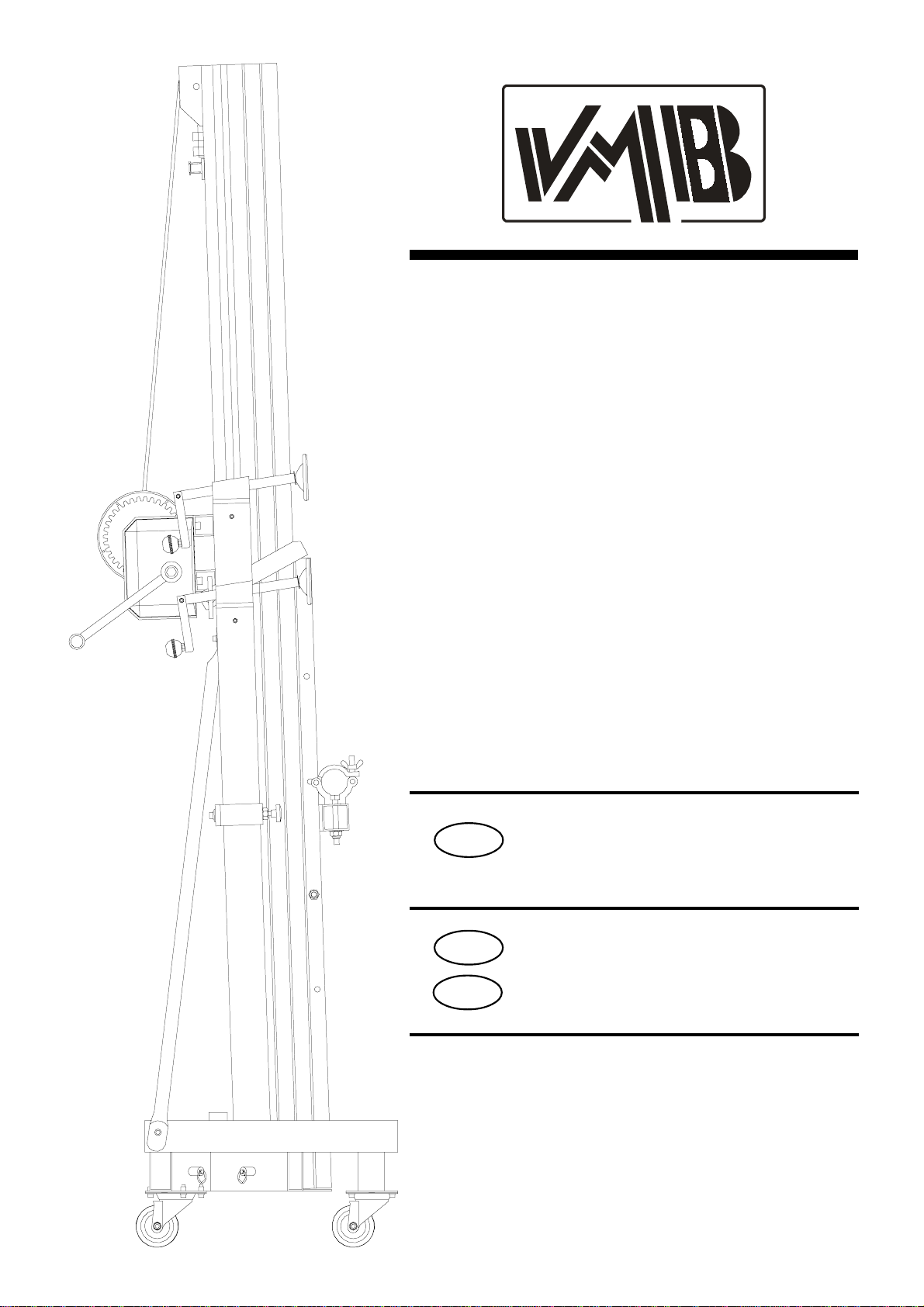
TORRE ELEVADORA
TOWERLIFT
TRAVERSENLIFT
PIED ÉLÉVATEUR TL-070
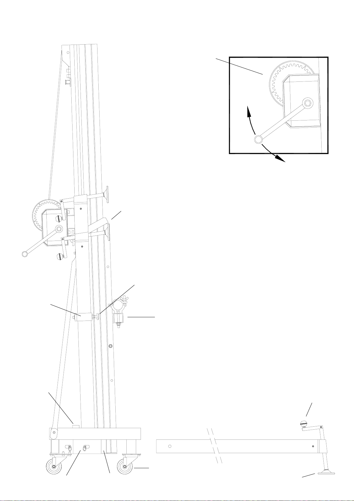
W
N1
N2
V
P
Q
H
T
F
R
U
J
S
TL-070
O
Manual de instrucciones ESPAÑOL
CONTENIDO
1. Introducción
2. Datos técnicos
3. Normas de seguridad
4. Instrucciones de uso
5. Mantenimiento
6. Resolución de problemas
1. INTRODUCCION
Estimado usuario,
Lea atentamente este manual.
Observe los datos técnicos y siga las normas
de seguridad antes de utilizar la torre eleva-
dora.
Los elevadores VMB son sometidos a
durísimaspruebasparagarantizarlamáxima
fiabilidad y resistencia. La torre TL-070 está
especialmente concebida para trabajar con
totalfiabilidadyseguridad.Sumecanismode
elevación incorpora el sistema de seguridad
ALS «auto-lock safety» exclusivo de VMB.
Este manual deberá estar disponible
permanentemente junto a la torre elevadora.
En caso de necesitar piezas de repuesto,
diríjase a su distribuidor habitual. Solamente
deben utilizarse piezas de repuesto origina-
les. El usuario perderá todos sus derechos
de garantía si incorpora cualquier repuesto
queno sea original o realizacualquier modifi-
cación en la torre.
Para cualquier consulta sobre la torre deberá
indicar el número de serie y año de construc-
ción.
2. DATOS TECNICOS
2.1 - Torre elevadora modelo TL-070
2.2 - Diseñada para levantar cargas en
sentido vertical a diferentes alturas.
2.3 - Carga máxima elevable : 250 Kg.
2.4 - Carga mínima elevable : 50 Kg.
2.5 - Altura máxima : 6,40 m.
2.6 - Altura mínima : 2,20 m.
2.7 - Superficie de la base : 1,99 x 1,99 m.
2.8 - Peso de transporte : 113 Kg.
2.9-Materialdeconstrucción:Cuerpoprinci-
pal en perfil de aluminio extrusionado 6082-
T6.BaseypatasenperfildeacerosegúnDIN
2394. Gatillos y cremallera de seguridad en
acero ST-37.
2.10 - Sistema deslizante sobre patines de
nylon de 4 tramos accionado por una combi-
nación de cable de acero en doble sirga y
cadenas,todoelloguiadoporpoleasacanala-
das con cojinetes de rodamiento a bolas.
Sistema exclusivo VMB (mod. ut. pen.
200202230)
2.11 - Cabrestante : 900/1000 Kg. de carga
máximaconfrenoautomáticoderetenciónde
la carga. Certificación CE y GS VBG 8.
2.12-Cable:AcerosegúnDIN3060.Calidad
180 Kg/mm2resistente a la torsión. Diámetro
6 mm.
2.13 - Cadenas de suspensión de mallas
juntas 4x4 de 1/2'' capacidad máxima 3.600
Kgs.
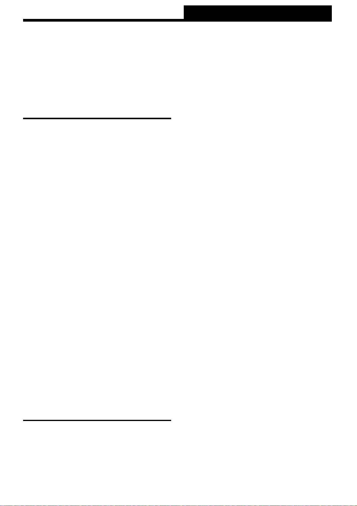
2.14 - Platillos estabilizadores ajustables en
las patas, con apoyos antideslizantes de
caucho.
2.15 - Anclaje de las patas por gatillos de
seguridad.
2.16-Niveldeburbujaparaajustarlaposición
vertical de la torre.
2.17 - Protección antióxido y acabado por
cadmiado electrolítico.
2.18 - Ruedas direccionables para facilitar
eltransportedelatorreenposiciónvertical
y plegada hasta su emplazamiento de
trabajo.

Manual de instrucciones ESPAÑOL
3. NORMAS DE SEGURIDAD.
3.1 - El elevador TL-070 es una máquina
diseñada para la elevación de cargas en
sentido vertical, NUNCA se debe utilizar
como plataforma elevadora de personas.
3.2- Colocarelelevadorsóloensuperficies
duras y planas, verificando que está en
posición vertical, mediante el nivel de bur-
buja(F)situadoeneltramobase.Ajustarsi
fuera necesario con los platillos de apoyo
(Q), girando la manivela (H) en el sentido
adecuado. Nunca utilice cuñas ni elemen-
tos extraños para equilibrar el elevador.
3.5 - No se debe sobrepasar la capacidad
decargamáximaindicadaenlaetiquetade
características del elevador y en este ma-
nual de instrucciones.
3.4 - Nunca se debe elevar una carga sin
antes verificar que está correctamente
apoyaday centradaenlossoporteseleva-
doresadecuados,deformaqueelpesode
la carga sólo actúe en sentido vertical.
3.3 - Comprobar que las patas están co-
rrectamente montadas y sujetas por sus
pasadores retenedores de seguridad.
K
g
s
!
Manual de instrucciones ESPAÑOL
3.11 - No utilice nunca el elevador sobre
ninguna superficie móvil o vehículo.
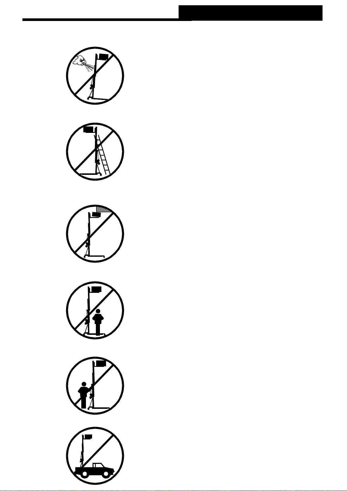
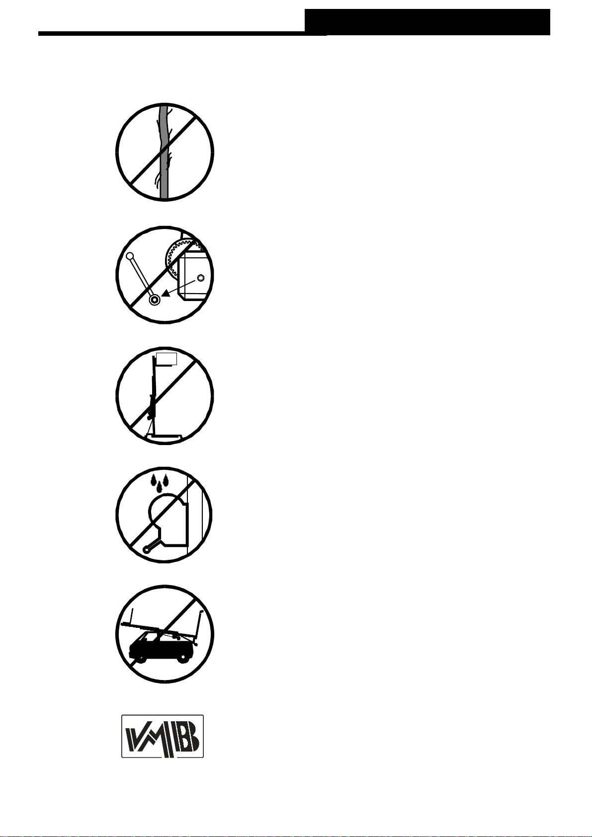
3.6- Siexisteposibilidaddevientofuerteo
en ráfagas, coloque el elevador en suelo
firmeyasegúrelo con la ayuda de tirantes.
Nunca fije un tirante sobre un vehículo o
cualquierotroelementoquepuedadespla-
zarse.
3.10 - No desplace nunca el elevador si se
encuentra con la carga elevada. No es
aconsejable realizar ningún tipo de movi-
miento,nitansiquierapequeñosajustesde
posicionamiento.
3.9- Nuncasepongadebajodelacargani
permita la presencia de otras personas en
la zona de trabajo del elevador.
3.8-Tengacuidadocontodotipodesalien-
tes por encima del elevador como corni-
sas, balcones, letreros luminosos, etc...
Es muy importante evitar la presencia de
cablespordebajodelaalturadetrabajodel
elevador.
3.7-Nouseescalerasencimadelelevador
ni las apoye en él para realizar ningún tipo
de trabajo.
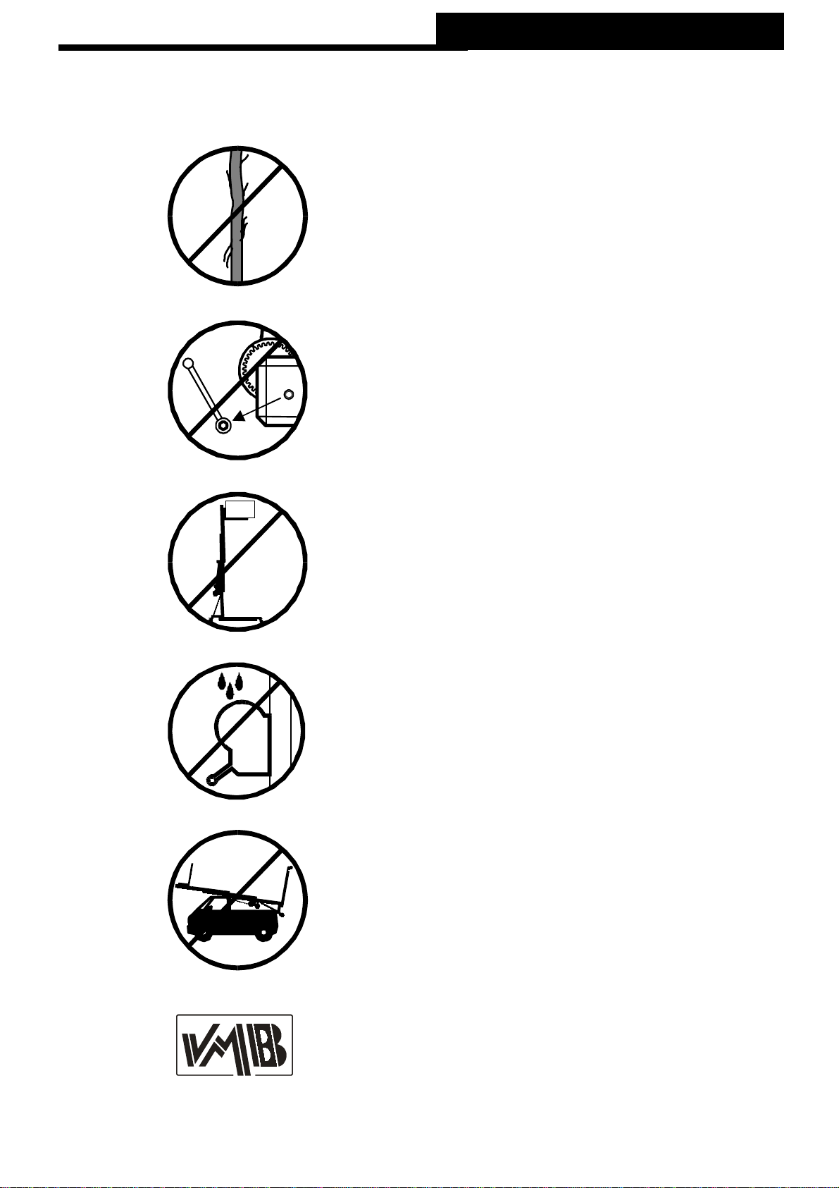
3.12 - Antes de utilizar el elevador, verifi-
que el estado del cable. El cable no debe
presentar rotura de hilos o aplastamiento.
NUNCA usecablesdefectuososyencaso
dedudacambie el cable.Sóloutilicecable
de acerosegúnDIN3060.Calidad180Kg/
mm2resistente a la torsión.
3.16 - Para el transporte del elevador hay
que bajar todos los tramos.
3.15-Noengrasenilubriqueelmecanismo
de freno del cabrestante. Los discos de
freno, han sido engrasados con una grasa
especialresistentealcalorylapresión.No
deben ser utilizados otros productos para
evitarinfluirnegativamenteenelfunciona-
miento del freno.
3.14 - La carga mínima para un funciona-
mientodelfrenosinproblemasesde50Kg.
Sinestacarga mínima el freno no actuará.
3.13 - Nunca desmonte la manivela del
cabrestantesielelevadorestáconcargay
elevado.
3.17 - Solamente deben utilizarse piezas
de repuesto originales.
ORIGINAL
-50
Manual de instrucciones ESPAÑOL

4. Instrucciones de uso.
4.1 - Coloque la torre elevadora apoyada en
susruedasdetransporte(T)sobreunasuper-
ficie plana y firme en su emplazamiento de
trabajo.
4.2 - Saque las patas de su soporte para
transporte (S) e insértelas a fondo en sus
alojamientosdetrabajo(V)comprobandoque
quedan sujetas por los gatillos retenedores
(R).
4.3 - Ajuste la posición vertical de la torre
mediantelosplatillosdeapoyoregulables(Q)
girando las manivelas de las patas
estabilizadorasparalograrquelaburbujadel
indicador de nivel (F) quede centrada en el
círculo.
4.4- Coloquelosbrazosdecargaenposición
horizontalyfíjelosconlospasadoresdesegu-
ridad. También puede elevar todo tipo de
cargassueltas(nuncapuentes)usandodirec-
tamente las abrazaderas alicraft del carro
elevador.
VMB aconseja los kit de elevación SU-070 y
BS-070, especialmente diseñados para la
elevación de cargas con la torre TL-070.
4.5 - LA CARGA MÁXIMA ES DE 250 Kg.
Nunca debe sobrecargarse la torre por enci-
ma de su carga máxima de trabajo (250 kg).
Laseguridaddetrabajoeslomásimportante.
Coloque la carga sobre la torre mediante un
soporte adecuado según el caso, de forma
que el peso de la carga sólo actúe en sentido
vertical. La carga mínima es de 50 Kg.
4.6 - Colocar la carga
Cuando utilice brazos de carga coloque
SIEMPREla carga lo más cercaposible de la
torre. La carga máxima de la torre TL-070
disminuye con la distancia al cuerpo de la
torre. Véase cuadro de cargas en función de
la distancia.
Para montajes con el kit de elevación VMB
BS-070,obrazosdecargasimilares,la capa-
cidad máxima de la torre depende de la dis-
tancia de carga en el soporte.
El Kit SU-070 está preparado para la carga
frontal de trusses de sección triangular o
rectangular de todas las dimensiones desde
25 cm a 52 cm. El Kit BS-070 de brazos
puede utilizarse tanto para la carga lateral
como frontal.
La carga máxima elevable con estos bra-
zos es de 250 kg cuando el centro de la
carga se sitúa a menos de 25 cm del carro
elevador.
Manual de instrucciones ESPAÑOL
A 25 cm 250 kg
B 30 cm 208 kg
C 40 cm 156 kg
D 50 cm 125 kg
E 60 cm 104 kg
F 70 cm 89 kg
G 80 cm 78 kg
H 90 cm 69 kg
I 100 cm 62 kg
Distancia del centro
de la carga a la torre Carga máxima
elevable

Cargar un puente
Para elevar un puente de manera LATERAL
puede colocarlo apoyado sobre el kit de bra-
zos BS-070. Cuando trabaja con UNA sola
torre también puede apoyarlo sobre las
abrazaderas del carro. NUNCA utilice las
abrazaderas para elevar con varias torres.
Paracargarpuentesdemanerafrontal utilice
el Kit de brazos cortos SU-070. Este kit per-
mite cargar todo tipo de trusses de sección
triangularorectangularentre25 y52cm.Con
el Kit de brazos largos BS-070 también pue-
den cargar trusses frontalmente.
Cargar estructuras
Para elevar puentes y sistemas estructurales
convariastorresalavez,utilicesiempreelKit
debrazoslargosBS-070 apoyandolaestruc-
turasobredichosbrazosdeformaqueestano
quede fijada rígidamente.
NUNCA cargue las estructuras directamente
sobrelasabrazaderasalicraftdelcarro cuan-
dolacargadebaserelevadaporvariastorres
enfrentadas y de manera simultánea.
MUY IMPORTANTE: Cuando se utilizan dos
torres para elevar un puente, o varias torres
para elevar una estructura rectangular o de
cualquier otra forma, es muy dificil que varias
personas accionen los cabrestantes y eleven
o bajen las torres exactamente por igual. En
un momento determinado cada torre puede
estar situada a una altura muy diferente de
las demás.
Es necesario que las sujeciones de la estruc-
turapermitan lasholgurasyarticulaciones ne-
cesarias para absorber las diferencias entre
la altura de cada torre. Con una fijación rígi-
da, si la diferencia de nivel es importante, la
fuerza del brazo de palanca generado forza-
rá lateralmente las torres pudiendo llegar a
frenarlasybloquearlas.Además puede llegar
a deformar la propia estructura de truss.
Manual de instrucciones ESPAÑOL
Sistema de seguridad ALS
LatorreTL-070disponedelsistema de segu-
ridad ALS autolock security (gatillo rojo).
ALSesunmecanismodeseguridadpatentado
y exclusivo de VMB. El sistema ALS bloquea
automáticamente la torre en cualquier posi-
ción que se deje. Cada tramo de cadena in-
corporaademásunsistema deseguridadALS
(automatic lock security) que bloquea el tra-
mo en el caso poco probable de rotura de la
cadena.
4.7 - Elevar:
Noelevarlatorresinuna carga mínima de 50
kg. Para elevar quite el bloqueo (O) y gire la
manivela del cabrestante. La carga se eleva-
rá hasta la altura deseada.
En caso de subir la torre sin carga o con una
cargainferior a 50 kg, lossistemas de seguri-
dadbloquearánlatorreautomáticamenteala
altura elevada y no podrá bajarse. Podría lle-
gar a bajar el tramo del cable dejando las ca-
denas sueltas. La torre quedará bloqueada y
para poder bajarla será necesario colgar del
carro elevador una carga superior a 50 kg.
Entonces habrá que subir de nuevo la torre
hastatensarcableycadenas,para liberar los
sistemas de seguridad. Una vez tensado el
cable y las cadenas se podrá bajar normal-
mente, manteniendodesenclavadoel gatillorojo
ALS AutoLock.
4.8 - Aguantar:
Sueltelamaniveladelcabrestanteylatorrese
mantendrá en esa posición por la actuación
del freno automático accionado por la carga.
La torre puede dejarse en cualquier posición
intermedia que se necesite, soltando simple-
mente la manivela.
4.9 - Descenso:
Para bajar la torre levante el gatillo rojo de
seguridad y manteniéndolo levantado, gire la
manivela del cabrestante. La carga irá des-
cendiendoconlosdiferentestramos has-
ta que la torre quede completamente
plegada a su altura mínima.

Latorrepuededejarseencualquierposición
intermediaquesenecesitedelmismomodo
que al subir la carga.
En caso de que el gatillo esté bloqueado por
la carga, hay que subir ligeramente la torre
girandolamaniveladelcabrestanteparades-
pués,unavezliberadoelgatillo,irbajandocon
normalidad.
4.10-Transporte:
Pliegue la torre bajando completamente los
tramos.Unavezplegada fijeelcarroelevador
con el soporte (O). Desmonte las patas
liberando los gatillos de retención y coló-
quelas en su posición de transporte (S).
Apriete los tornillos (J).
5. Mantenimiento.
5.1 - Compruebe periódicamente el estado
delcable. Siuncablepresentaroturadehilos
o aplastamiento, debe ser substituido inme-
diatamente por otro nuevo. No utilice la torre
con cables en mal estado. Utilice solamente
cable de acero DIN 3060 resistente a la tor-
sión.
5.2- Latorreelevadorasesuministracomple-
tamente engrasada de fábrica. No obstante,
se recomienda engrasar periódicamente
(según el uso) la corona dentada del
cabrestante, los cojinetes del árbol de ac-
cionamiento y el buje, la rosca de la mani-
vela y los tramos.
ATENCION:
No engrasar ni lubricar el me-
canismo del freno.
Noesnecesarioengrasarlosdiscosdefreno.
Losdiscos de freno han sido engrasados con
una grasa especial resistente al calor y la
presión.Nodebenserutilizadosotrosproduc-
tos para evitar influir negativamente en el
funcionamiento del freno.
Manual de instrucciones ESPAÑOL
5.3 - La torre elevadora TL-070 debe ser
comprobadaporunexpertocomomínimouna
vez al año de acuerdo con su utilización.
5.4 - Solamente deben utilizarse piezas de
repuesto originales para garantizar una
continuada seguridad de uso.
El usuario pierde todos los derechos de ga-
rantía si incorpora otros repuestos que no
sean originales o lleva a cabo cualquier
modificación en el aparato.
5.5-Parasolicitarcualquierpiezaderepuesto,
debe indicarse su número de referencia, que
figura en las hojas de despiece de este
manual.
6. Resolución de problemas.
-Si la torre va muy dura...
Compruebe si la carga total excede los 250
Kg. No sobrepase esta carga máxima.
Compruebe que la carga esté colocada co-
rrectamente. Consulte el cuadro de cargas y
distancias del punto 4 de este manual. La
cargano debeestardemasiadoseparada(ex-
cesiva distancia) del cuerpo de la torre. Colo-
que la carga correctamente y siempre lo más
cerca posible del cuerpo de la torre.
En caso de trabajar con varias torres, com-
pruebequelas torresesténelevadasala mis-
ma altura. Si las alturas son diferentes, las
torres estánrealizandouna fuerza lateralque
provoca su frenado. Iguale siempre las altu-
ras y suba de forma nivelada.
Compruebe que las fijaciones de la estructura
a elevar no sean rígidas permitiendo las
holguras necesarias para una elevación
manual.
Coloque siempre una fijación de forma que
permita ligeros desplazamientos del apoyo.
Utilice los Kits de carga SU-070 y BS-070.

-Si la torre no baja
Puede ser debido a que la torre se ha eleva-
do sin carga o con una carga inferior a 50 Kg.
Coloque en el carro elevador (ref.7056) una
carga superior a 50 Kg. Eleve de nuevo la
torre para tensar las cadenas y liberar el sis-
temadeseguridad. Después gire la manivela
delcabrestantey haga descender la torrecon
normalidad, manteniendo levantado el gatillo
rojo ALS.
Si está utilizando varias torres, para elevar
un puente o estructura, puede que al tratar
de bajar la estructura las torres queden blo-
queadas. Esto es debido a que la acción ma-
nual para bajar varias torres no es exacta-
mente la misma y pueden haber diferencias
de altura entre el conjunto de torres. Com-
pruebe las sujeciones de la torre a la estruc-
tura. Si trabaja con sujeciones rígidas para
cargar las estructuras a la torre, esa rigidez
impide la absorción de las diferencias de al-
tura entre las torres y estas pueden quedar
frenadas debido al esfuerzo lateral de palan-
ca,locual activa el sistema deseguridadALS
de los tramos bloqueando la torre.
Primero suba las torres que estén más bajas
hasta la misma altura que las demás. Des-
puésvuelvaa elevar todas las torresporigual
unos 10 cm, hasta tensar las cadenas y libe-
rar los sistemas de seguridad ALS de los tra-
mos de cadena. De esta manera desbloque-
ará las torres. Para finalizar, baje todas las
torres a la vez, de forma que el conjunto esté
lo más nivelado posible.
Cambieinmediatamente laformadesujeción.
Siemprequetrabajeconvariastorresdeje un
mínimo de juego en las sujeciones para
absorver las diferencias de altura durante la
elevación y el descenso.
VMB recomienda los soportes PS-04 y
PS-05 con sujeción tipo U.
Manual de instrucciones ESPAÑOL
La torre elevadora TL-070 ha sido probada según la norma
BGV C1 (GUV 6.15) / BGG 912 (GUV 66.15)
obteniendo la certificación de prueba con fecha 08/07/02
Las pruebas han sido realizadas por
IBB ingenieure sachverständige
Dipl. - Ing. univ. Olaf Brandt
Nollendorfstrasse 18
D-45472 Mülheim an der Ruhr
La torre TL-070 suministrada corresponde a la muestra verificada.
Declaración de conformidad CE según la norma de la CE sobre
máquinas 89/392/CE
Declaramos que las torres VMB
-modelo TL-070
corresponden, con un uso correcto para la elevación y descenso de cargas, a las
disposiciones de la normativa de máquina 89/392/CE, las demás normativas CE y
ampliaciones correspondientes.
VMB Española S.A.
Calle 2 - Pol. Ind. Picassent
E-46220 Picassent
TORRE ELEVADORA
TL-070
PRODUCTO FABRICADO POR:

Quick Operation Guide ENGLISH
CONTENTS
1. Introduction.
2. Technical information.
3. How to place the load
4. How to load structures
5. How to load a bridge
6. Trouble shooting
1. INTRODUCTION
Dear customer,
In order to operate the towerlift TL-070 in
a safe and reliable manner, follow the
instructions in this booklet.
Before operating the lift, read the instructions
carefully.
Please note the technical information.
Our products undergo very rigorous testing
understrictconditionsandtheyaremonitored
continuously during the manufacturing
process.
In order to guarantee the lift function and
safety,theoriginalpartsofthemanufacturer's
designmustbeused.Ifanyparts other than
those of the manufacturer are used, or the
product is modified in any way, the user
forfeits all warranty rights to claim.
VMB reserves the right to modify the
productspecificationswithoutpriornotice.
The model type, production year and
serial number must be quoted in any
queries or orders for spare parts.
2. TECHNICAL INFORMATION
2.1 - Towerlift TL-070.
2.2 - Designed to lift loads vertically to
differentheightstosupportlightingsystems.
2.3 - Maximum load : 550 lbs / 250 Kg.
2.4 - Minimum load : 110 lbs / 50 Kg.
2.5 - Maximum height : 21 ft / 6,4 m.
2.6 - Minimum height : 7.2 ft / 2,2 m.
2.7 - Area of base : 6.5x6.5 ft / 1,99x1,99 m.
2.8 - Unit weight : 248.6 lb / 113 Kg.
2.9 - Construction material : Main body in
extrudedaluminium6082-T6profile.Baseand
legsaremadeofsteelprofileaccordingtoDIN
2394.CatchesandsafetyrackofST-37steel.
2.10 - Exclusive system (mod. ut. pen.
200202230)
2.11 - Winch:900/1000Kg.ofmaximumload
with automatic brake to stop the load.
2.12-Cable:SteelDIN3060.Quality180Kg/
mm2twist resistant. Cable diameter : 6 mm.
2.13-Chains4x4of1/2''maximumcapacityof
3.600 Kgs.
2.14 - Adjustable stabilizing feet with ruber
non-slip supports.
2.15 - Safety catches to anchor the legs.
2.16- Spiritleveltoadjustthetowervertically.
2.17-Antirustprotectionandcadmiumplating.
2.18 - Swivel wheels to transport the lift when
folded.

Quick Operation Guide ENGLISH
3. SAFETY PRECAUTIONS.
3.1 - The TL-070 is a machine designed to
elevateloadsupwardsinaverticaldirection,
NEVER should it be used as a platform to
elevate people.
3.2- Onlyplacetheliftonhard,flatsurfaces
alwayscheckingthatitisinaverticalposition
byusingthebubblelevelindicator(F)found
on the base section. Adjust the outrigger
stabilisers(Q)byturningthecrankstolevel
if necessary. NEVER use wedges or other
foreignobjectstobringthelifttoequilibrium.
3.5 - The maximum load indicated on the
characteristics label and the instructions
manual should not be exceeded
3.4 - NEVER should the lift be used to
elevate a load that has not been properly
checked. It is necessary to verify that the
load is correctly supported and centred on
theappropriateliftsupportsothattheweight
of the load will only elevate in a vertical
direction.
3.3 - Check that the outriggers are placed
and set-up correctly using the pins safety
system.
K
g
s
!

Quick Operation Guide ENGLISH
3.11-NEVERusetheliftonavehicleorany
other mobile surface.
3.6 - If there is a possibility of strong winds
or gusts, place the lift on the ground firmly
andsecureitwiththeuseofstraps.NEVER
attach a strap to a vehicle or any other
object that can possibly be moved.
3.10 - NEVER move the lift whilst it is
carrying a load. It is not advisable to carry
out any type of movement even small
positional adjustments.
3.9-NEVERallowanyteammemberbelow
theloadoranybodyelseintheliftsoperating
zone.
3.8-Takecarewithallobstaclesabovethe
liftanditsextensionzonesuchascornices,
balconies, and luminous signboards. It is
very important to avoid the presence of all
types of cables below the extended lift.
3.7 - Do not use stepladders on the lift or
use it as a support for them.
3.12 - Before using the lift, check the state
of the cable. The cable should not contain
broken threads or show any signs of
crushed/flattenedareas.NEVERusefaulty
cables, always change them if there is any
doubt. Only use steel cables reference:
DIN3060.Quality: 180KG/mm andtorsion
resistant.
3.16 - All sections must be lowered during
transportation.
3.15-Donotgreaseorlubricatethewinch’s
breakingmechanism.Thebrakediskshave
been greased with a special heat and
pressureresistantsolution.Otherproducts
shouldnotbeusedtoavoidnegativeeffects
regarding the braking mechanism.
3.14-Theminimumloadtoavoidproblems
regardingthebreakingmechanismis50KG.
Without this load the brake will not work.
3.13 - NEVER take apart the crank of the
winch when the lift is carrying a load or
extended.
3.17-Onlyoriginalreplacementpartsshould
be used.
ORIGINAL
-50
Quick Operation Guide ENGLISH
Quick Operation Guide ENGLISH
4. USAGE INSTRUCTIONS.
4.1 - Place the lift on a firm, flat surface in the
area it is to be used supported its transport
wheels (T).
4.2-Removetheoutriggersfromtheirtransport
supports (S) and fully insert them into their
positions (V) checking that they are fixed by
the pins (R).
4.3 - Adjust the outrigger stabilisers (Q) by
turning the cranks to level the lift. Ensure it is
in a vertical position by using the bubble level
indicator (F) found on the base section. The
bubble should be in the centre of the circle.
4.4 - Place the forklifts in a horizontal position
and secure them with the pins.
VMB recommends the SU-070 Elevation Kit
andtheBS-070ElevationKitwhichhaveboth
been especially designed for loading and
elevating with the TL-070.
4.5 - THE MAXIMUM LOAD IS 250KG. The
liftshouldNEVERbeoverloaded(over250KG).
Safety at work is the most important element.
Place the load onto the lift using an adequate
supportaccordingtotheneed,usesothatthe
weightoftheloadwillonlyelevateinavertical
direction. The minimum load is 50KG
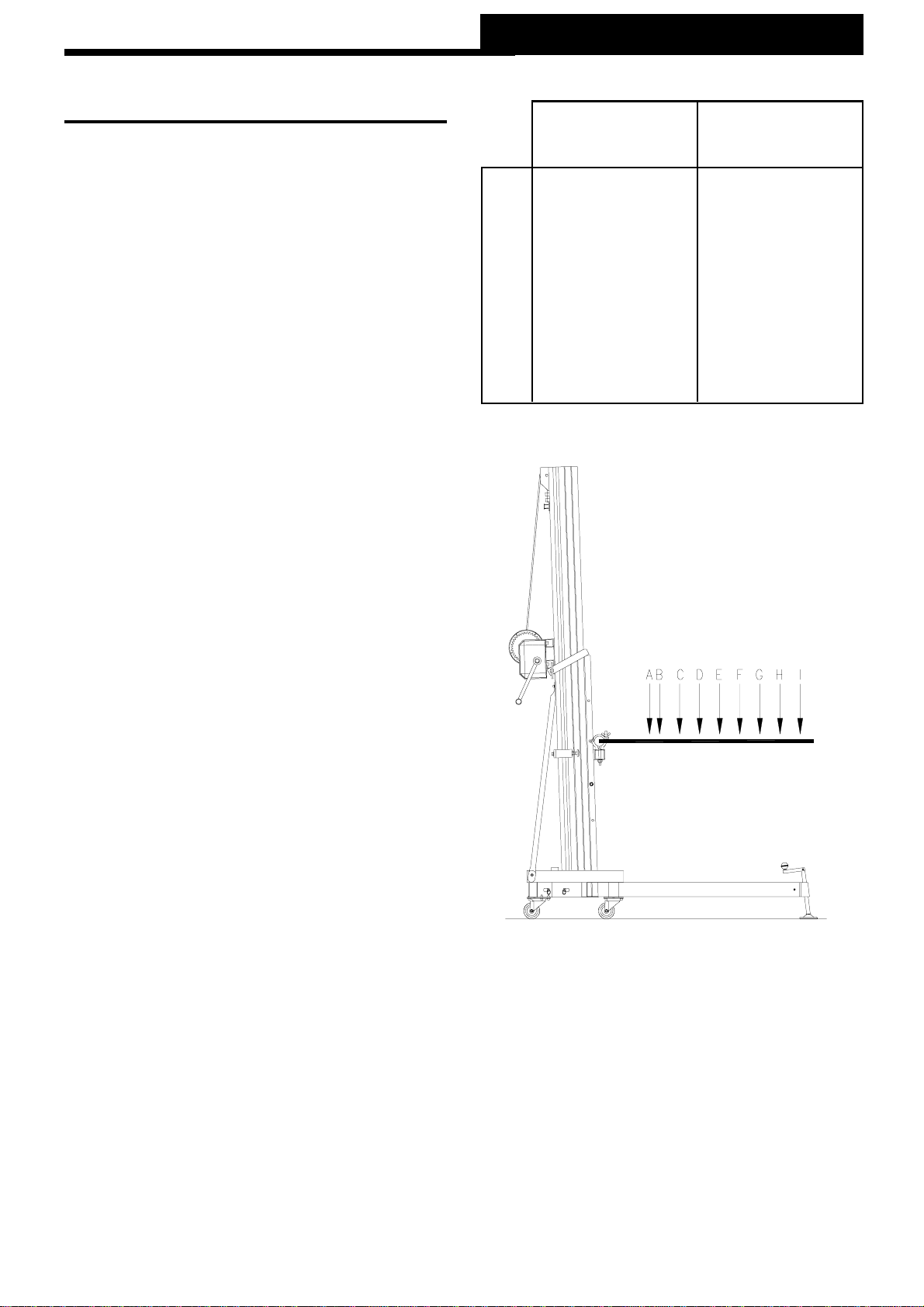
4.6 - How to place the load
Always load as close to the tower as possi-
ble.Themaximumloaddiminishesaccording
to the distance from the body of the tower as
illustratedinthe diagram below.
Themaximumloadis250kgwhentheload’s
centre is at 25 cm from the lifting carriage of
thetowerlift.
VMB recommend the use of the VMB special
supportkitsSU-070 and BS-070.TheSU-070
Kit is prepared for frontal loading of triangular
orrectangulartrussesofallthedimensionsfrom
25 cm to 52 cm. The BS-070 Kit can be used
forfrontalor lateralloading.
A 10 ‘‘ - 25 cm 550 lb - 250 kg
B 12 ‘‘ - 30 cm 457 lb - 208 kg
C 16 ‘‘ - 40 cm 343 lb - 156 kg
D 20 ‘‘ - 50 cm 275 lb - 125 kg
E 24 ‘‘ - 60 cm 229 lb - 104 kg
F 28 ‘‘ - 70 cm 196 lb - 89 kg
G 32 ‘‘ - 80 cm 171 lb - 78 kg
H 36 ‘‘ - 90 cm 152 lb - 69 kg
I 40 ‘‘ -100 cm 136 lb - 62 kg
Load centre’s
DISTANCE
to the lifting carriage
Maximum lifting
LOAD
How to load a bridge
To lift a bridge you can use the VMB kits SU-
070 and BS-070. To load bridges of both tri-
angularandrectangulartrussesmeasuringbe-
tween 25 and 52 cm, the SU-070 Kit can be
usedforfrontalmountings.BS-070canbeused
for frontal or lateral loading. NEVER use the
halfcouplersalicrafttoliftabridge.

How to load structures
To elevate structures it is necessary to use
the BS-070 Kit. The arms support the struc-
ture but not in a rigid position.
DO NOT LOAD STRUCTURES DIRECTLY
ONTO THE ALUMINUM HALF COUPLERS
ON THE TROLLEY
CAUTION
Whentwotowersare used to elevate a bridge
or many towers to elevate a structure of any
type, it is almost impossible that two or more
people co-ordinate the winches elevating or
lowering the loads, at exactly the same pace.
At a certain point each tower will be extended
to a height different to that of the others.
For this reason it is necessary that the
subjections of the structure account for this
and allow for these differences. With a rigid
fixation and if the level difference is signifi-
cant, the force generated from the handle of
the winch will deform the structure and apply
alateral forcetothe liftscausingthem tobreak
andblock.
4.7 - Lift:
DONOTELEVATETHELIFTWITHOUTAMI-
NIMUMLOADOF50kg
Elevatingthe liftwithoutany minimumloadwill
cause the ALS to block the lift while extended
and it will not descend, it may even lower the
section of the cable leaving the chains loose.
The lift will remain blocked but to release and
lower it, it is necessary to apply the minimum
load of 55 lb (25kg). Then the lift needs to be
raisedsoastotightenthecableandchainsto
freethe securitysystems.Whenthe cableand
chains have been tightened it is possible to
lower the lift normally, of course making sure
theredALSlatchisheldup.
Quick Operation Guide ENGLISH
SecuritysystemALS
TheTL-070incorporatesthe patentedsecurity
systemALS(Automatic Lock Security).
This VMB red trigger system automatically
blocksthetowerinthepositionitisleftin.Each
section of chain has an ALS that blocks the
section in the unlikely event of the chain
breaking.
4.8 - Hold:
Thetowercanbeleftinanyintermediateposition
whichwouldbenecessary.Juststopturningthe
handle of the winch and left it. The automatic
brakeofthewinchwillblockitandholdtheload.
4.9 - Lowering:
To low the load lift the blockade on the red
safetytriggerandrotatethehandleofthewinch
until the tower will be completely folded at his
minimalheight.Theloadwillbelowed.
4.10 - Transport:
For the transport of the tower is necessary to
fold the machine lowering completely all the
profiles. Once the towerlift is folded it is very
important to blockade the lifting carriage with
itstransportsupport(O).Getoutthelegsleaving
the blockade on the triggers and put them in
their transport lodging (S). Then press the
fasteningscrews.

5. MAINTENANCE.
5.1- Regularlycheckthestateofthecable.Ifthe
cable has broken threads, or if it shows any
signs of crushed/flattened areas, it should be
changed and replaced immediately by a new
one. Do not use the lift if the cables are in bad
condition. Only use steel cables reference:
DIN 3060 torsion resistant.
5.2 - The lift is supplied from the factory
completely greased. However, it is
recommendedtoperiodicallygreaseaccording
to use, the gearing, the axis bearings, the
spiral of the crank, and the sections.
REMEMBER: NEVER grease or lubricate
the breaking mechanism.
It is not necessary to grease the brake
disks. The brake disks have been greased
with a special heat and pressure resistant
solution. Other products should not be used
to avoid negative effects regarding the brak-
ingmechanism.
5.3-AnexpertshouldchecktheTL-070atleast
once a year according to its usage. Consult
yourdistributor.
5.4-Onlyoriginalreplacementpartsshouldbe
used to guarantee continued safety during
usage.
Theuserloses all guaranteerightsifhe/she
usesreplacementpartsthat are not original
orifhe/shemakesanymodificationtothe
apparatus.
5.5 - To order any replacement parts, the
reference number on the replacement parts
pagesinthismanualshouldbeindicated.
Quick Operation Guide ENGLISH
6. TROUBLE SHOOTING
- HARD TO ELEVATE:
Checkthatthetotal load does not exceed 550
lb(250 kg) DO NOTTO EXCEEDTHEMAXI-
MUM LOAD.
Check that the load is not placed excessively
from the body of the tower according to dia-
gram in this quick operation guide.
ALWAYS LOAD AS CLOSE TOTHELIFTAS
POSSIBLE.
Check that the lifts in use when elevating a
bridge or truss structure are at equal heights
and not causing force laterally causing them
to brake. If this is the case adjust the heights
and continue to elevate the load in a horizon-
tal position. Check that the fixations of the
bridge or structure are not rigid whilst elevat-
ing and that they allow for the necessary
movements during elevation. Place the fixa-
tion so that it allows for slight displacements
of the support. Use the loading kits SU-070 &
BS-070.
-DIFFICULTY IN LOWERING THE LIFT
WHEN EXTENDED.
As explained above, it is necessary to apply
theminimum loadof 110lb(50kg).Ifthisisnot
the case and the lift does not descend, carry
outthefollowing:
A.Extendthelifttotightenthecableandchains
tofree the securitysystem.
B. When the cable and chains have been
tightened it is possible to lower the lift
normally
C.MakesuretheredALS latch is held up.
Table of contents
Languages:
Other VMB Lifting System manuals


Popular Lifting System manuals by other brands

Vestil
Vestil LLCB-202058 manual

Shenxi
Shenxi SC Series instruction manual

FEIN Service
FEIN Service 9 08 01 012 00 8 instruction manual

Surewerx
Surewerx Strongarm 816B owner's manual

IMER
IMER TR 225 2V Operating, maintenance, spare parts manual

AMGO Hydraulics
AMGO Hydraulics OHX-10 Installation and service manual


Erickson
Erickson 07451 quick start guide

HMS-VILGO
HMS-VILGO Homelift 2 user guide

Challenger Lifts
Challenger Lifts CL20 Installation, operation & maintenance manual

ReadyLift
ReadyLift 66-2215 installation instructions

morse
morse 400A-72SS-110 Operator's manual

Rotary
Rotary SPOA10NB Series Operation and maintenance manual