Nibe RCU 10 User manual

R
INSTALLATION AND MAINTENANCE INSTRUCTIONS
RCU 10
FOR FIGHTER 360P/1130/1230/1320
MOS GB 0546-1 511401
RCU 10
LEK


Contents 1
RCU 10
General
Setting table ........................................................ 2
Product description .............................................. 3
Installation
Assembly .............................................................. 4
Network connections ............................................ 5
GSM modem ........................................................ 6
Digital inputs ........................................................ 6
Indicators
Indicators on RCU 10 .......................................... 7
Indicator on GSM modem .................................... 7
Starting
General ................................................................ 8
RCU 10 configuration software ............................ 8
Logging in ............................................................ 10
Web interface
Web browser requirements .................................. 11
Menu overview .................................................... 11
Web interface – Settings
Language selection .............................................. 12
Log ...................................................................... 12
Module ................................................................ 13
E-mail .................................................................. 13
Network ................................................................ 13
Modem ................................................................ 14
User ...................................................................... 14
Web interface – FIGHTER 360P
Overview page .................................................... 15
Operating data .................................................... 16
Operating data, extended .................................... 17
Alarm/status ........................................................ 18
Log ...................................................................... 18
SMS commands – FIGHTER 360P
SMS commands .................................................. 19
Web interface – FIGHTER 1130/1230
Overview page .................................................... 20
Operating data .................................................... 21
Operating data, extended .................................... 22
Operating data, external units .............................. 22
Alarm/status ........................................................ 23
Log ...................................................................... 23
SMS commands – FIGHTER 1130/1230
SMS commands .................................................. 24
Web interface – FIGHTER 1320
Overview page .................................................... 25
Operating data .................................................... 26
Operating data, external units .............................. 27
Operating data, compressor ................................ 28
Log ...................................................................... 28
SMS commands – FIGHTER 1320
SMS commands .................................................. 29
Component locations
Component locations .......................................... 30
List of components .............................................. 30
Miscellaneous
Technical specifications ...................................... 31
Enclosed kit .......................................................... 31
Frequently asked questions
Frequently asked questions ................................ 32

General
RCU 10
2
In order to get the ultimate benefit from your RCU 10 communications unit you should read
through these Installation and Maintenance Instructions.
Installation date
Installation engineers
MAC ID
Date __________ Signature __________________________________
To be completed when the communications unit has been installed

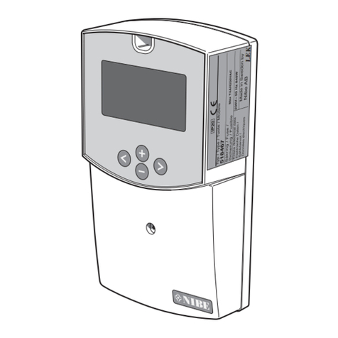
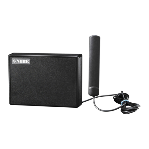
The RCU 10 consists of a communications module, a
GSM modem with an antenna and a separate power
supply unit with jack for plugging into a wall socket.
The antenna can be placed outside the enclosure.
The RCU 10 enables operations to be controlled and
monitored using a computer connected to a local net-
work or via the Internet. The integrated GSM module
also enables control and monitoring by sending text
messages from a mobile phone. For the GSM function
to work, the communications module must be
equipped with a valid GSM subscription. This may for
example be a cash card or a special telematics sub-
scription.
It is possible to connect to the RCU 10 two indepen-
dent switch functions to detect external events such as
a movement alarm or freezing protection.
Note that all configuration of the unit requires that a
computer is connected, even if only text messaging is
going to be used.
General 3
RCU 10
Product description
NOTE!
If a SIM card is used, it must be
configured so that a PIN code is not
used to obtain connection. This can be
done in a mobile telephone or by the
service provider.

Installation
RCU 10
4
Stick the product label securely to the cover. The label
can be placed in any orientation, depending on the
location of the unit.
Open the plastic cover by separating its two halves.
The RCU 10 is placed outside the heat pump and its
best location is mounted on a wall.
Connect the communication cable in accordance with
the appropriate product description. Then continue with
the instructions under the heading “Final installation”.
FIGHTER 360P
Connect the black communication cable (105) from
the heat pump to the RCU 10, position (4).
Earlier versions of the FIGHTER 360P do not have the
cable (105). Then connect the accompanying black
communication cable between the RCU 10 position
(4) and the heat pump modular connector that is on
the CPU card (34). For communication to work, the
CPU card in the FIGHTER 360P must have version
number 2.00 or higher.
FIGHTER 1230
Connect the accompanying black communication
cable between the RCU 10 position (4) and the heat
pump modular connector that is on the CPU card (34).
For communication to work, the CPU card in the
FIGHTER 1230 must have version number 1.03 or
higher.
Assembly
34
Final installation
Connect the 4-pole modular cable to the network
adapter output. Plug the network adapter into a near-
by wall socket. Refit the plastic cover to the RCU 10.
The heat pump must be configured, to permit commu-
nication with the RCU 10. This is done via the service
menus. Refer to the “Installation and Maintenance
Instructions” for the respective products.
Tip: Try to find a wall socket for the network adapter
that is fed from a different fuse than the fuse for the
heat pump supply. The RCU 10 will then be able to
detect if the heat pump shuts down.
105
34
34
FIGHTER 1320
Connect the accompanying black communication
cable between the RCU 10 position (4) and the heat
pump modular connector that is on the CPU card (34).
For communication to work, the CPU card in the
FIGHTER 1320 must have version number 1.10 or
higher.
LEK
34
FIGHTER 1130
Connect the accompanying black communication
cable between the RCU 10 position (4) and the heat
pump modular connector that is on the CPU card (34).
For communication to work, the CPU card in the
FIGHTER 1130 must have version number 1.03 or
higher.

Installation 5
RCU 10
Internetuppkoppling
(t ex modem)
Router alt. Hub/Switch
Dator RCU 10
Värmepump
Dator
RCU 10
Internetuppkoppling
(t ex modem)
Värmepump
The RCU 10 has a connection (5) for 10/100 Mbps
Ethernet.
Connect the unit to a network, or alternatively direct to
a computer with the Ethernet cabling. For connection
to a router or a hub/switch a straight-through cable
must be used, and for direct connection to a computer
a crossover cable must be used.
A network with the RCU 10 connected to a router or
hub/switch is recommended. For connection direct to
a computer with Internet connection, two network
cards are required in the computer, and it must run
continuously in order to provide the RCU 10 access to
the Internet.
Internet connection is not necessary to be able to
install and configure the unit, but is required for
access to the unit via the Internet.
Network connections
Internet connection
(e. g. modem)
Router, alternatively
Hub/Switch
Computer RCU 10 RCU 10
Computer
Heat pump Heat pump
Internet connection
(e. g. modem)

Installation
RCU 10
6
The RCU 10 contains a GSM modem, that can be
used for sending and receiving text messages, and for
reading log files generated by the product.
Antenna
The RCU 10 is delivered with an antenna, that is ini-
tially kept rolled up inside the outer casing. If reception
at the installation site is poor, try moving the antenna
outside the box. The antenna section has a piece of
self-adhesive tape that can be used to secure the
antenna, for example to a window.
GSM modem
LEK
1
2
1
2
3
The RCU 10 has two digital inputs (7) (optically isolat-
ed) for connection of an external signal. The inputs
shall be 10 – 24 VDC for an active high signal and 0 –
2 VDC for an inactive signal.
Terminal number Function
24 Voltage feed (12 VDC)
23 Signal ground (GND)
22 Not used (NC)
21 Not used (NC)
20 Digital In 2+ (DI2+)
19 Digital In 2- (DI2-)
18 Digital In 1+ (DI1+)
17 Digital In 1- (DI1-)
(Digital In 1- and Digital In 2- are internally connected
together).
Digital inputs
SupplyVoltage9-32VAC/DC,1W
ART#:0120999901
Mac ID:00:30:11:FB:01:35
NETBITERMODBUS TCP/RTU GATEWAYMADEIN SWEDEN
45:2003
LEK
Serial interface
(For GSM modem)
8
74
5
SIM card
The modem requires a 3.3 V SIM card. See the illus-
tration below for installation instructions. The SIM card
must be configured so that a PIN code is not used to
obtain connection. This can be done in a mobile tele-
phone or by the service provider. For a telephonic
data connection to the RCU, the SIM card needs to
have a special telephone number for computer com-
munication. Refer to the section “Web interface – Set-
tings” > “Modem” for further information.
If a cash card is used, remember to refill it at regular
intervals so that communication is not cut off by the
operator.

Indicators 7
RCU 10
LEK
Not lit The RCU has no voltage
Steady green RCU 10 in operation
Steady orange On starting
Not lit No contact with network
Steady green 10 Mbit/s link
Steady orange 100 Mbit/s link
Not lit Waiting
Flashing green TX serial channel
Flashing red RX serial channel
Steady orange On starting
Not lit Waiting
Flashing green Ethernet traffic
Flashing red Ethernet conflict
Not lit Unit has no voltage
Rapid flashing - Searching for GSM net-
work or
- SIM card missing or
- No GSM cover
Slow flashing Normal operation. Contact
with GSM network.
Indicators on RCU 10
Indicator on GSM modem

Starting
RCU 10
8
The RCU configuration software is a PC-based pro-
gram that can be used to prepare different network-
parameters in the RCU 10. The program can search
for RCU 10 units on an Ethernet network, after which
the IP address, network mask, gateway, DNS, etc.
can be set. DHCP can also be activated in the unit.
Install by running the installation program Setup-Net-
BiterConfig.exe that is on the supplied CD.
System requirements
■Pentium 133 MHz
■5 MB free hard disk space
■Windows 95/98/ME/NT/2000/XP
■Network card (Ethernet)
If a different operating system than Windows is used –
contact NIBE support for further information.
IP: IP address for the RCU 10
SN: Network mask
GW: Gateway
DHCP: Dynamically assigned IP address (On/Off)
Version: Software version
Type: Product type
MAC: Ethernet MAC address
Search for connected units
When the program starts, it will automatically search
for an RCU 10 network connection. A list will be dis-
played of all units that are found. A new search can be
made by pressing the “Scan” button.
MAC ID in hex code.
The RCU 10 has a preset IP address: 10.200.1.X,
where X is the final digit in the MAC ID (on the label on
the side of the unit).
NOTE! Images and settings on the following pages
may show some difference, depending on the brows-
er, settings and the version of the RCU, as well as the
heat pump configuration.
RCU 10 configuration software
General

Starting 9
RCU 10
Changing IP settings
Double-click on the desired unit in the list to change
the IP settings. A new window will open, in which the
new settings can be entered.
To obtain the necessary information concerning your
network settings, please contact your network admin-
istrator.
RCU 10 configuration software
IP Address: IP address for the RCU 10
Subnet mask: Network mask
Default gateway: Gateway
Primary DNS: Primary DNS (any)
Secondary DNS: Secondary DNS (any)
Host name: Host name for RCU 10 (any)
The preset password is ”admin”.
On pressing the “Set” button the RCU 10 will restart,
after which the new settings will be activated.
The new settings can be tested by opening a browser
and entering the set IP address. If DHCP is activated,
a new search can be made with the program to see
which IP address has been assigned to the RCU 10.
NOTE!
Only set DHCP to “On”
if a DHCP server is
available on the network.
NOTE!
If the password is forgotten, there is
no way to retrieve it. The RCU 10
must be returned to NIBE where a
complete reset will take place.
All the settings that have been made,
including user settings, will disappear.
NOTE!
The password is case-sensitive, i. e.
the precise password must be entered
in respect of upper and loser case
characters.
NOTE!
Only A-Z, a-z and 0-9 are permitted to
be used in the user ID and password,
the symbol characters cannot be used.

Starting
RCU 10
10
Start the browser (such as Internet Explorer) and
enter the selected IP address in the RCU 10. If the
IP address is chosen for example to be 10.2.15.21,
then ”http://10.2.15.21” is entered into the browser
address field, followed by pressing the Enter button.
The following or a similar image will be displayed:
To access the product’s internal web page for the first
time, enter “admin” into both entry fields. The pass-
word will be changed later, and new users can be
added (refer to the ”Web interface – Settings” >
”Users” section).
If there is a problem logging in, check that ”Caps Lock”
is not activated for the keyboard.
Logging in

Web interface 11
RCU 10
The web pages are optimised for Internet Explorer 6.0
and Mozilla Firefox. Other browsers may also work,
but the pages may appear different.
The browser must support Java.
If Java is not supported, the component may be
downloaded at
http://www.java.com/en/download/manual.jsp
The actual displayed images may differ somewhat,
depending on the currently installed configuration.
The RCU 10 has two menus, a top menu and a side
menu. The top menu provides navigation to different
areas of the NIBE web site (requires Internet connec-
tion) and resetting of the RCU 10 to another language
(requires administrative or writing authority).
The side menu provides navigation in the RCU 10’s
internal web pages. The side menu has differences
depending on which product is used together with the
RCU 10.
If “Miscellaneous” is selected, a new menu appears:
Overview diagram
This page shows in a schematic way how the heat
pump operates. The temperature and operational sta-
tus can be read here. See the respective product
descriptions.
Operating data
This page shows in detail how the heat pump oper-
ates. A selection of the most often used measured val-
ues can be read and adjusted here. See the respec-
tive product descriptions.
Extended operating data/ external/ compressor
Further measured values are shown here for reading
and adjustment. See the respective product descrip-
tions.
Alarm/status
This page shows whether any alarms have been acti-
vated. FIGHTER 1320 does not have this page, and
any activated alarms are shown on the overview page
instead.
Settings
Here are various web interface and RCU function set-
tings.
These menus are common to all heat pumps and are
described in the “Web interface – Settings” section.
FIGHTER 360P FIGHTER 1130/1230 FIGHTER 1320
Web browser requirements
Menu overview

Web interface – Settings
RCU 10
12
In “Settings” – “Log” are entered the desired paramet-
ers, logging interval and type of log-in.
The selected parameters and logging interval affect
the total log time. With several selected parameters
and a a more frequent logging interval, the RCU 10
memory fills up more quickly and the total log time is
reduced.
The logging interval defines at which intervals the
logged values shall be saved. Selectable intervals are
every 10 seconds, 30 seconds, 1, 2, 5, 10, 30 and
60 minutes.
The logging type can be selected from 3 different
modes: No logging, Stop logging when the log is full or
Circular logging (the oldest measured value is erased
and replaced by new when the log is full).
The buttons at the bottom can be used to
mark/unmark all the measured values and save
selected settings.
The log settings menu has differences depending on
which product is used.
The following illustration is from the FIGHTER 1320.
Here the logged values are put on different pages,
that are selected from the scrolling list. The FIGHTER
1130/1230 also has its logged values placed on differ-
ent pages. Otherwise, the logging settings for the dif-
ferent products operate in the same way.
NOTE!
The settings must be saved for
activation to take place.
To change the language used in the RCU 10, click on
the flag for the desired language in the top menu, or
select ”Settings” – “Choose language” and then click
on the desired language. To activate the selected lan-
guage, click on ”Save”.
Language selection
Log

Web interface – Settings 13
RCU 10
In “Settings” – ”Miscellaneous” – “Module” information
concerning where the module is installed can be
entered. The informationen in the “Building” display is
then used when the RCU 10 sends an alarm via E-
mail or as a text message.
The RCU 10 can be restarted remotely by clicking on
“Restart”.
Module
Here the settings for handling E-mail can be made.
This is necessary for enabling the RCU 10 to send
alarms via E-mail to selected users.
E-mail
Here the basic settings for network connection can be
made. These are the same settings that can be made
with the aid of the RCU 10 configuration program.
Network
NOTE!
If the RCU 10 is to be reached via the
Internet it is important to configure a
firewall that will allow the reception of
incoming web traffic (port 80).
NOTE!
Only set DHCP to “On”
if a DHCP server is
available on the network.

Web interface – Settings
RCU 10
14
Here all the settings that affect the GSM modem can
be made.
SMS settings
If ”SMS Alarm” is activated, the RCU 10 will send a
text message (SMS) to all alarm recipients as soon as
an alarm is activated by the heat pump.
To enable SMS commands to be sent to the RCU 10,
“SMS Command” must be set to “On”.
If “Number check of incoming SMS” is set to “Off” the
SMS command “?STATUS” is accepted from all tele-
phone numbers (e.g. for demonstration). Note that
other SMS commands always require that the number
has been recorded on a user.
PPP server settings
A PPP server is used to permit incoming connections
to the RCU 10 via the modem. This requires that the
GSM subscription includes a service where a special
telephone number for computer communication is pro-
vided. It is this computer number that will then be used
during a called computer connection to the modem.
The subscription thus has two different telephone
numbers in this case, one for SMS and one for incom-
ing computer connections. Contact your GSM opera-
tor to see if this service will be possible.
The connection can be used to look at web sites or to
fetch a log file from the RCU 10. State the user
name/password that are to be used on logging in, and
which IP address shall be sent out to the person con-
necting. This IP number shall be in the same sub-net-
work as occupied by the RCU 10, and the IP number
must be free. If, for example, the RCU 10 has
193.12.34.21, the issued IP number must be
193.12.34.X, where X is between 1 and 254.
Modem
NOTE!
The password is case-sensitive and
only A-Z, a-z and 0-9 are permitted to
be used in the user ID and password,
which means that the symbol
characters cannot be used.
Here takes place handling of users who shall have the
right to log in to the RCU 10. Click on “Add” to add a
new user. Existing user information can be edited by
clicking on the names.
■User ID: This ID is used when logging on to the
RCU 10 via a browser.
■Name: User’s name.
■E-mail: The user’s E-mail address to which alarms
are to be sent.
■Mobile: The mobile telephone number that is
approved for incoming SMS commands and to
which alarms are to be sent.
■Alarm receiver: Here is defined which types of
alarm the user is to receive. Several boxes can be
marked.
- Prio 1: All alarms except those below.
- Prio 2: Low priority alarms.
- Digital inputs: Alarms from digital inputs.
- Heat pump status changed: Alarm warning that
the status of the heat pump has changed.
■User level:
- Read: The user may only look at the web site and
cannot change anything.
- Write: The user may look at the web site and
change parameters on the operations pages.
- Admin: The user may look at the web site and
has full authority to change configuration and
parameters.
■Password: This password is used when logging on
to the RCU 10 via a browser. The password is to
be repeated for verification.
User

Web interface – FIGHTER 360P 15
RCU 10
This is the first page to be displayed after logging in. It
shows an overview with information concerning the
most important parameters of the heat pump.
A Supply temperature Menu 2.0*
B Return temperature Menu 2.6*
C Temperature, compressor sensor Menu 1.1*
D Temperature, hot water sensor Menu 1.0*
E Evaporation temperature Menu 5.0*
F Extract air temperature Menu 5.1*
G Exhaust air temperature Menu 5.2*
H Outside temperature Menu 4.0*
I Operating indications
Lit lamp indicates an active function.
* Equivalent menu number in FIGHTER 360P
Overview diagram
C
D
HG IFE
A B

Web interface – FIGHTER 360P
RCU 10
16
The change in value presumes that the user has
logged in with writing or administration authority.
Operating data for several measured values is shown
in table format for easy viewing.
M1.0 shows that the equivalent menu in FIGHTER
360P is 1.0.
At S86 the status for the component numbered 86 in
FIGHTER 360P’s component list is shown.
To change a value, click on ”arrow down” and select a
value from the scrolling list, confirm with ”Set”. After a
few seconds the change is confirmed by FIGHTER
360P and the relevant value is updated.
Operating data

Web interface – FIGHTER 360P 17
RCU 10
In this form the heat regulation parameters can be
changed by clicking on ”arrow down” and selecting a
value from the scrolling list, confirming thereafter with
”Set”.
The change in value presumes that the user has
logged in with writing or administration authority.
Operating data, extended

Web interface – FIGHTER 360P
RCU 10
18
This form shows the common alarms that the heat
pump has indicated.
External alarm inputs DI1 and DI2 are not concerned
with the heat pump functions but are self-defined func-
tions, e.g. movement alarm and freezing protection.
Factory settings
Click on the “Factory settings” button to reset all set-
tings in the FIGHTER 360P to their original states.
Restarting
Click on the “Restart FIGHTER 360” button to restart
the FIGHTER 360P.
Alarm/status
Here the log files that are in the RCU 10 can be
fetched. The parameter log contains selected logged
values (see the “Web interface – Settings” > “Log”
section).
The alarm log contains all the alarms that have been
indicated and a number of temperatures registered at
the time of each alarm.
The log files can be cleaned out by clicking on the
“Clean log file” button for the appropriate log.
The log files are in CSV format, which is a standard
format that can be imported into several kinds of cal-
culation program for further processing.
Log
Table of contents
Other Nibe Control Unit manuals
Popular Control Unit manuals by other brands

Delta
Delta DVP08ST11N instruction sheet

red lion
red lion ITMA DC quick start guide

Ublox
Ublox SARA-N2 Series System integration manual

Aqua Medic
Aqua Medic Ocean Light LED Operation manual

Electronics
Electronics MagnaValves 500-24 instruction manual

CleaverBrooks
CleaverBrooks CB780 Operation and maintenance manual