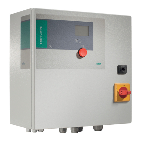
Wilo SK 602N User manual

de Einbau- und Betriebsanleitung
en Installation and operating instructions
fr Notice de montage et de mise en service
it Istruzioni di montaggio, uso e manutenzione
el Οδηγίες εγκατάστασης και λειτουργίας
tr Montaj ve kullanma kılavuzu
hu Beépítési és üzemeltetési utasítás
pl Instrukcja montażu i obsługi
cs Návod k montáži a obsluze
ru Инструкция по монтажу иэксплуатации
ro Instrucţiuni de montaj şi exploatare
SK 602N, SK 622N
2 129 143-Ed.01/2012-09-Wilo

Fig. 1: Fig. 2:
Fig.3a:
Fig.3b:
1
2
1
∅4
∅4
130 103
110
130
113
113 ∅6
∅6
∅4
∅4
130 103
115
130
113
113 ∅6
∅6

Fig.4: a.) b.) c.)
Fig.5:

Fig.6:

Installation and operating instructions SK 602N/SK 622N 19
English
Installation and operating instructions
1 General
About this document
The language of the original operating instructions is German.
All other languages of these instructions are translations of the
original operating instructions.
These installation and operating instructions are an integral
part of the product. They must be kept readily available at the
place where the product is installed. Strict adherence to these
instructions is a precondition for the proper use and correct
operation of the product.
The installation and operating instructions correspond to the
relevant version of the product and the underlying safety regu-
lations and standards valid at the time of going to print.
EC declaration of conformity:
A copy of the EC declaration of conformity is a component of
these operating instructions.
If a technical modification is made on the designs named there
without our agreement or the declarations made in the instal-
lation and operating instructions on product/personnel safety
are not observed, this declaration loses its validity
2Safety
These operating instructions contain basic information which
must be adhered to during installation, operation and mainte-
nance. For this reason, these operating instructions must, with-
out fail, be read by the service technician and the responsible
specialist/operator before installation and commissioning.
It is not only the general safety instructions listed under the
main point “safety” that must be adhered to but also the special
safety instructions with danger symbols included under the fol-
lowing main points.
English
20 WILO SE 09/2012
2.1 Indication of instructions in the operating instructions
Symbols:
General danger symbol
Danger due to electrical voltage
NOTE
Signal words:
DANGER!
Acutely dangerous situation.
Non-observance results in death or the most serious of injuries.
WARNING!
The user can suffer (serious) injuries. 'Warning' implies that
(serious) injury to persons is probable if this note is disre-
garded.
CAUTION!
There is a risk of damaging the product/unit. 'Caution' con-
cerns possible damage to the product that could occur if this
note is disregarded.
NOTE: Useful information on handling the product. It draws
attention to possible problems.
Information that appears directly on the product, such as
• identification for connections
• rating plate
• warning sticker
must be strictly complied with and kept in legible condition.

Installation and operating instructions SK 602N/SK 622N 21
English
2.2 Safety instructions for installation and maintenance work
The safety instructions included in these installation and oper-
ating instructions, the existing national regulations for accident
prevention together with any internal working, operating and
safety regulations of the operator are to be complied with.
The operator must ensure that all installation and maintenance
work is carried out by authorised and qualified personnel, who
are sufficiently informed due to their own detailed study of the
installation and operating instructions.
Safety instructions of the installation and operating instruc-
tions for the pump are to be observed at all times when
working on the switchgear and the pump/system!
DANGER! Danger of electric shock!
Work may only be carried out on the product/unit if they are
switched off and secured against being switched on again.
Immediately on conclusion of the work, all safety and protec-
tive devices must be put back in position and/or recommis-
sioned.
2.3 Unauthorised modification and manufacture of spare parts
Unauthorised modification and manufacture of spare parts will
impair the safety of the product/personnel and will make void
the manufacturer's declarations regarding safety.
Modifications to the product are only permissible after consul-
tation with the manufacturer. Original spare parts and accesso-
ries authorised by the manufacturer ensure safety. The use of
other parts will absolve us of liability for consequential events.

English
22 WILO SE 09/2012
3 Transport and interim storage
Immediately check the product for any transit damage on
arrival. If damage is found, the necessary procedures involving
the forwarding agent must be taken within the specified period.
CAUTION! Risk of damage to property!
Incorrect transport and interim storage can cause damage to
the product.
• The switchgear must be protected against moisture and
mechanical damage caused by blows/impact.
• It must not be exposed to temperatures outside the range
–10°C to +40°C.
4 Intended use
Wall-mounted unit for the electrical connection of single-
phase and three-phase pumps with integrated thermal winding
contacts (WSK) for monitoring the winding temperature (full
motor protection). Automatic reactivation of pump after power
failure and automatic fault acknowledgement after cooling off
of the motor.
DANGER! Risk of fatal accident!
The switchgear is not protected against explosions and may
not be operated in the explosive area.
Always install the switchgear outside the explosive area.
Intended use of the pump/installation also includes following
these instructions.
Any other use is not regarded as intended use.

Installation and operating instructions SK 602N/SK 622N 23
English
5 Product information
5.1 Type key
5.3 Scope of delivery
•Switchbox,complete
• 4x M20 threaded cable connections
• Installation and operating instructions
5.4 Accessories
Accessories must be ordered separately:
• SK 601N
See the catalogue for a detailed list
SK 602N/SK 622N
SK = switchbox
602N/622N = device type
5.2 Technical data
Operating voltage 1~230 V (L, N, PE)
3~400 V (L1, L2, L3, N, PE)
Frequency 50/60 Hz
Protection class IP55
Switching capacity AC-3 1~230 V, 1 kW
3~400 V, 3 kW
3~230 V, 1.5 kW
Power dissipation SK 602N 1.93 W
Power dissipation SK 622N 2.4 W
Switching capacity SSM (SK 622N only) Max. 250 V/1 A/150 VA
Switching capacity SBM (SK 622N only) Max. 250 V/1 A/150 VA
Temperature range -10 °C to +40 °C
Housing Polycarbonate/polyamide, RAL 7035
4x punch stampings for M20
Housing dimensions (W x H x D) 130 x 130 x 110 mm (SK 602N)
130 x 130 x 115 mm (SK 622N)

English
24 WILO SE 09/2012
6 Description and function
6.1 Switchbox description
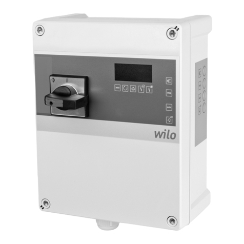
SK 602N
Includes the contactor for full motor protection tripping, the
On/Off switch, with integrated run signal light (Fig. 1, item 1),
terminals for external potential-free activation/deactivation
and terminal rail (Fig. 5).
SK 622N
Like SK 602N, but additionally with potential-free contacts for
external run signal (SBM) and fault signal (SSM), see Fig. 6, as
well as fault signal lights (Fig. 2, item 2).
Motor protection
The selection of the correct motor protection is a decisive fac-
tor for the service life and operational reliability of a circulation
pump. Motor protection switches are no longer suitable for
multi-speed pumps, since their motors have deviating rated
currents in the different stages, which require different fuses.
Motor fuse protection in Wilo pumps can be ensured by taking
the following measures:
• Blocking current-proof motors: No motor protection
required.
The pump motors are designed in such a way that current flow-
ing through the winding cannot cause any damage in the event
of overloading or blocking. This applies both to single-phase
and three-phase versions, depending on the rated motor
power.
•Pumps with full motor protection and Wilo-SK 602/622N
tripping unit or Wilo switchgear/control device
Implementation of full motor protection by means of thermal
winding contacts (WSK) within the motor winding. This applies
both to single-phase and three-phase versions, depending on
the rated motor power.

Installation and operating instructions SK 602N/SK 622N 25
English
6.2 Switchbox function
The switchbox SK 602N/SK 622N switches the single phase or
three phase power supply for the connected pump, depending
on the WSK or the manual/external control, via a contactor (K1).
6.2.1 Switchgear operating elements
Pushbutton/latch switch (Fig. 1 and 2, item 1):
• OFF (not illuminated): No voltage is applied to the pump
• ON (illuminated in green): A voltage is applied to the pump
6.2.2 Display elements of the switchgear (for SK 622N only)
Red lamp (Fig. 2, item 2):
•OFF: Fault-freeoperation.
• ON: WSK error (thermal winding contact tripped)
7 Installation and electrical connection
DANGER! Risk of fatal accident!
Improper installation and electrical connection can result in
fatal injury.
• Installation and electrical connection may only be carried out
by qualified personnel and in accordance with the applicable
regulations.
• Adhere to regulations for accident prevention
7.1 Installation
Install the switchgear in a dry, vibration-free and frost-proof
location.
Protect the place of installation from direct sunlight.
To fasten the switchgear, open the upper part of the housing:
• Loosen the 4 cover fixing screws

English
26 WILO SE 09/2012
CAUTION! Risk of damage to property!
Incorrect handling of the switchgear can result in property
damage.
Do not drill through the housing into the wall!
• The housing and electronic components might be damaged.
• Damage to the housing (cracks) can lead to leaks.
• For wall-mounted installation, fasten the switchgear to the wall
with dowels and screws. Dimensions for the drilling pattern in
acc. with Fig. 3a and 3b, screw diameter 4 mm, bore diameter
6mm.
Before mounting the switchgear, break out the required punch
stampings on the side of the electric cable inlet and outlet for
mounting the threaded cable connections.
WARNING! Risk of injury!
Improper work on the housing can cause injuries.
• When opening the housing punch stampings, wear protective
goggles, since housing parts can chip off.
• When opening the housing punch stampings, wear protective
gloves to protect your hands from sharp edges.
To open the punch stampings, use a slotted screwdriver with a
5.5 mm blade, a 300 g hammer as well as a deburrer.
To open the pre-punched holes, place the screwdriver blade
perpendicular on the marked edge of the inner punch stamping
(Fig. 4a) and punch the punch stamping out with a light ham-
mer tap on the head of the screwdriver (Fig. 4b).

Installation and operating instructions SK 602N/SK 622N 27
English
CAUTION! Risk of damage to property!
Improper work on the housing can result in property damage
(Fig. 4c).
• Damage to the housing (cracks) can lead to leaks.
• Burrs on the breakouts can impair the mounting of the
threaded cable connections. To use safely, deburr the break-
throughs.
Use the threaded cable connections (M24) included in delivery
as needed and fasten to the housing.
7.2 Electrical connection
DANGER! Risk of fatal accident!
A fatal shock may occur if the electrical connection is not
made correctly.
• Only allow the electrical connection to be made by an electri-
cian approved by the local power supply company and in
accordance with the local regulations in force.
• Observe the installation and operating instructions for the
pumps and accessories.
• Disconnect the power supply before any work.
• Check to ensure that all connections (including potential-
free contacts) are voltage-free.
CAUTION! Risk of damage to property!
An incorrect electrical connection can cause damage to
property.
• If the wrong voltage is applied, the motor or switchgear can
be damaged!
• Control via the triac/semiconductor relay is not possible.

English
28 WILO SE 09/2012
• The type of mains, current and voltage of the mains connection
must match the details on the rating plate of the pump as well
as the rating plate specifications and documentation of the
switchgear.
• Provide fuse protection on the mains side (max. 10 A, slow-
blow) as well as a residual-current-operated protection switch
in accordance with the applicable regulations.
• To increase the operational reliability, we recommend the use
of an automatic circuit breaker (which disconnects all power
leads) with K characteristic.
• Feed the ends of the pump cable through the cable screw fit-
tings and cable inlets and wire them according to the markings
on the terminal strip (Fig. 5 or Fig. 6).
• The electrical connection must be established via a fixed power
cable (3 x 1.5 mm2, minimal cross-section), equipped with a
plug and socket connector or an all-pole switch with a mini-
mum contact opening width of 3 mm.
• To ensure drip protection and strain relief on the threaded cable
connection, use cables with a sufficient outer diameter and
screw the threaded cable connection tightly. In addition, the
cables near the screwed connection are to be bent to form a
drainage loop, to drain any accumulated drips.
• Earth the switchgear according to regulations.
• L1, (L2, L3), N, : Mains connection voltage: 3~400 VAC/
1~230 VAC, 50/60 Hz, DIN IEC 60038, alternatively, the mains
connection between the 2 phases of a three-phase network
earthed at the star point is possible with a delta voltage of
3~230 VAC, 50/60 Hz.

Installation and operating instructions SK 602N/SK 622N 29
English
7.2.1 Single phase mains connection 1~230 V (L, N, PE)
Power supply connection:
• Terminals 1 (K1), N and PE (X1)
Connect phase L1 on the contactor (K1) to terminal 1 and N, PE
on the terminal block (X1) according to the wiring diagram
(Figs. 5 and 6).
Pump connection:
• Voltage: Terminals 2 (K1), N and PE (X1)
• WSK: Terminals 15, 10 (X1)
The pump is connected directly on the contactor (K1) to termi-
nal 2 and N, PE on the terminal block (X1) according to the wir-
ing diagram (Figs. 5 and 6).
Connect the WSK connection of the pump on the terminal block
(X1) to terminals 10 and 15. If there is no WSK on the pump, a
jumper must be connected between terminals 10 and 15 on the
terminal block (X1).
7.2.2 Three-phase mains connection 3~400 V (L1, L2, L3, N,PE)
Power supply connection:
• Terminals 1, 3, 5 (K1), N and PE (X1)
Connect phases L1, L2, L3 on the contactor (K1) to the termi-
nals 1, 3, 5 and N, PE on the terminal block (X1) according to the
wiring diagram (Figs. 5 and 6).
Pump connection:
• Voltage: Terminals 2, 4, 6 (K1), N and PE (X1)
• WSK: Terminals 15, 10 (X1)
The pump is connected directly on the contactor (K1) to termi-
nals 2, 4, 6 and N, PE on the terminal block (X1) according to the
wiring diagram (Figs. 5 and 6).
NOTE: Incorrectly connecting the phases L1, L2, L3 can cause
the pump to turn in the wrong direction of rotation. Observe
the chapter “Rotation direction monitoring” in the installation
and operating instructions of the respective pump.

English
30 WILO SE 09/2012
Connect the WSK connection of the pump on the terminal block
(X1) to terminals 10 and 15. If there is no WSK on the pump, a
jumper must be connected between terminals 10 and 15 on the
terminal block (X1).
7.2.3 Two-phase mains connection 3~230 V (L1, L2, PE)/
(L2, L3, PE)/(L3, L1, PE) for AC pumps, 230 V
CAUTION! Risk of damage to property!
An incorrect electrical connection can cause damage to property.
• If the wrong voltage is applied, the motor or switchgear can
be damaged!
• This connection to two phases is only permissible for these
switchboxes and for AC pumps when the delta voltage in the
supply system is 230 V.
Power supply connection:
• Terminals 1 (K1), N and PE (X1)
When the delta voltage in the system is 230 V
Connect one of the phases L1/L2/L3 on the contactor (K1) to
terminal 1 and another phase L1/L2/L3 to terminal N of the ter-
minal block (X1) according to the wiring diagram. PE is con-
nected to terminal PE of the terminal block (X1).
Pump connection:
• Voltage: Terminals 2 (K1), N and PE (X1)
• WSK: Terminals 15, 10 (X1)
The pump is connected directly on the contactor (K1) to termi-
nal 2 and N, PE on the terminal block (X1) according to the wir-
ing diagram (Figs. 5 and 6).
Connect the WSK connection of the pump on the terminal block
(X1) to terminals 10 and 15. If there is no WSK on the pump,
a jumper must be connected between terminals 10 and 15 on
the terminal block (X1).

Installation and operating instructions SK 602N/SK 622N 31
English
7.2.4 Signalling and indicator contacts
DANGER! Risk of fatal accident!
A fatal shock may occur if the electrical connection is not
made correctly.
If the mains and SSM core are brought together in a 5-core
cable, the SSM core must not be operated using a protective
low voltage, since otherwise voltage transfers could occur.
For the switchbox SK 622N (Fig. 6), a collective fault signal
“SSM” is available as a potential-free N/C contact for an exter-
nal signal to the building automation and a collective run signal
“SBM” is available as a potential-free contact.
SSM: Apply the collective fault signal at terminals 11 and 14 of
relay K2 (Fig. 6).
NOTE: If there is integrated motor protection in the pump and
the WSK terminals 10 and 15 on the terminal block X1 are
bridged, the SSM signal is not available here.
SBM: Apply the collective run signal at terminals 13 and 14 of
contactor K1 (Fig. 6).
7.2.5 External control
For the external control of the switchbox (e.g. with a time
switch SK601N), the jumper at terminals 1 and 2 of the terminal
block (X1) must be removed. The external switch contact is
then to be connected to terminals 1 and 2. Alternatively to
SK601N, an external switch can also be connected, with which
the load switch (K1) is externally controlled for the pump.

English
32 WILO SE 09/2012
NOTE: It is only possible to externally control the pump via
SK 601N or a switch if the green push-button/latch switch is
switched on SK 602N or SK 622N.
8Commissioning
WARNING! Risk of injury and damage to property!
Incorrect commissioning can lead to injuries to persons and
damage to property.
• Commissioning by qualified personnel only!
• Observe the installation and operating instructions for the
pumps and accessories.
• It is imperative that the warnings from chapter 7 be heeded!
• Before commissioning the switchgear and the pump, check
whether these have been properly installed and connected.
The pump is commissioned according to the corresponding
pump documentation.
8.1 Operation
The pump is switched on/off manually by actuating the green
push-button/latch switch on the front side of the switchgear
SK 602N/SK 622N (Figs. 1 and 2, item 1) or via a potential-free
contact/time switch. Operation is indicated by the green con-
trol lamp in the push-button/latch switch.
NOTE: It is only possible to externally control the pump via
SK 601N or a switch if the green push-button/latch switch is
switched on SK 602N or SK 622N.
When the power supply is restored after a mains failure, the
motor is switched on again automatically.
For switchgear SK 622N, the motor protector is tripped by the
red fault control lamp (Fig. 2, item 2). The motor stays off until

Installation and operating instructions SK 602N/SK 622N 33
English
it has cooled off. The automatic fault acknowledgement of the
pump happens after the motor cools off.
NOTE: During the initial commissioning of the switchbox
SK622N, the red lamp lights up briefly.
When the motor protection trips repeatedly, the motor must be
checked electrically and mechanically. If necessary, Wilo cus-
tomer service should be notified.
Faults, causes and remedies
If the operating fault cannot be remedied, please contact a
specialist technician or the nearest Wilo customer service
location or representative.
Faults Causes Remedy
Pump is not run-
ning although the
power supply is
switched on.
(In the case of
SK 622N, the red
lamp is not illumi-
nated)
Greenpressureswitchon
the SK 602N/SK 622N is
switched off
Switch on the green
pressure switch (Figs. 1
and 2, item 1)
External control (e.g.
SK 601N) is connected,
but switched off
Switch on external con-
trol (e.g. SK 601N)
No jumper between ter-
minals 1 and 2 on the
terminal block X1
Place a jumper between
terminals 1 and 2 on the
terminal block X1
Pump is not run-
ning although the
power supply is
switched on.
(In the case of
SK 622N, the red
lamp is illumi-
nated)
WSK contact of the
pump not connected to
terminals 10 and 15
Connect WSK to termi-
nals 10 and 15
WSK of the pump was
tripped or is defective After the motor cools
off, the pump starts up
on its own.
For pumps without a
WSK, contacts 15 and 10
on the terminal block X1
are not bridged.
Bridge contacts 15 and
10 on the terminal block
X1.

English
34 WILO SE 09/2012
9 Spare parts
Spare parts are ordered via local specialist retailers and/or Wilo
customer service.
In order to avoid further inquiriesand incorrect orders, all data on
the rating plate should be specified for each order.
10 Disposal
Damage to the environment and risks to personal health are
avoided by properly disposing of and recycling this product.
1. Use public or private disposal organisations when disposing
of the entire product or part of the product.
2. For more information on proper disposal, please contact
your local council or waste disposal office or the supplier
from whom you obtained the product.
NOTE: The switchgear must not be disposed of with household
waste.
Subject to change without prior notice!
This manual suits for next models
1
Table of contents
Other Wilo Controllers manuals

Wilo
Wilo HiControl 1 User manual

Wilo
Wilo AlarmControl 1 User manual

Wilo
Wilo Stratos Demo User manual

Wilo
Wilo HiControl 1/FC User manual

Wilo
Wilo fluidcontrol ek User manual

Wilo
Wilo IR-Monitor User manual

Wilo
Wilo Control DigiCon User manual

Wilo
Wilo Control EC-Booster User manual

Wilo
Wilo AlarmControl 1 User manual

Wilo
Wilo ER 2 User manual