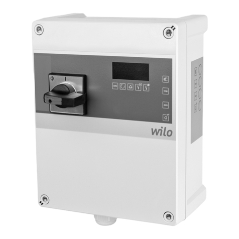
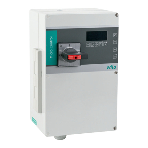
Wilo ER 2 User manual

Wilo-ER 2/ER 3-4
D Einbau- und Betriebsanleitung
GB Installation and Operating Instructions
F Notice de montage et de mise en service
NL Montage- en bedieningsvoorschriften
E Instrucciones de instalación y servicio
I Istruzioni di montaggio, uso e manutenzione
H Beépítési és üzemeltetési utasítás
PL Instrukcja montażu i obsługi
CZ Návod k montáži a obsluze
RUS
Instrukciä po montaΩu i qkspluataciœ
2 025 723-Ed.03/2007-09-DDD

Fig. 1
CO-ER System
Economy Regeltechnik

Fig. 2

Fig. 3

Fig. 4

Fig. 6
Fig. 5

1
D
1. Allgemeines . . . . . . . . . . . . . . . . . . . . . . . . . . . . . . . . . . . . . . 4
2. Sicherheit . . . . . . . . . . . . . . . . . . . . . . . . . . . . . . . . . . . . . . . . 4
3. Transport und Zwischenlagerung . . . . . . . . . . . . . . . . . . . . . . 4
4. Beschreibung von Erzeugnis und Zubehör . . . . . . . . . . . . . . . 4
5. Aufstellung / Einbau . . . . . . . . . . . . . . . . . . . . . . . . . . . . . . . . 5
6. Inbetriebnahme . . . . . . . . . . . . . . . . . . . . . . . . . . . . . . . . . . . 5
7. Wartung . . . . . . . . . . . . . . . . . . . . . . . . . . . . . . . . . . . . . . . . . 5
8. Störungen, Ursachen und Beseitigung . . . . . . . . . . . . . . . . . . 5
GB
1. General . . . . . . . . . . . . . . . . . . . . . . . . . . . . . . . . . . . . . . . . . . 7
2. Safety notes . . . . . . . . . . . . . . . . . . . . . . . . . . . . . . . . . . . . . . 7
3. Transport and Storage . . . . . . . . . . . . . . . . . . . . . . . . . . . . . . 7
4. Description of the Product and Accessories . . . . . . . . . . . . . . 7
5. Siting / Installation . . . . . . . . . . . . . . . . . . . . . . . . . . . . . . . . . 8
6. Commissioning . . . . . . . . . . . . . . . . . . . . . . . . . . . . . . . . . . . . 8
7. Maintenance . . . . . . . . . . . . . . . . . . . . . . . . . . . . . . . . . . . . . . 8
8. Faults - Causes and Remedies . . . . . . . . . . . . . . . . . . . . . . . . 8
F
1. Généralités . . . . . . . . . . . . . . . . . . . . . . . . . . . . . . . . . . . . . . . 10
2. Sécurité . . . . . . . . . . . . . . . . . . . . . . . . . . . . . . . . . . . . . . . . . 10
3. Transport et stockage avant utilisation . . . . . . . . . . . . . . . . . . 10
4. Description du produit et des accessoires . . . . . . . . . . . . . . . 10
5. Installation / Montage . . . . . . . . . . . . . . . . . . . . . . . . . . . . . . . 11
6. Mise en service . . . . . . . . . . . . . . . . . . . . . . . . . . . . . . . . . . . . 11
7. Entretien . . . . . . . . . . . . . . . . . . . . . . . . . . . . . . . . . . . . . . . . . 11
8. Pannes, causes et remèdes . . . . . . . . . . . . . . . . . . . . . . . . . . 11
NL
1. Algemeen . . . . . . . . . . . . . . . . . . . . . . . . . . . . . . . . . . . . . . . . 13
2. Veiligheid . . . . . . . . . . . . . . . . . . . . . . . . . . . . . . . . . . . . . . . . 13
3. Transport en opslag . . . . . . . . . . . . . . . . . . . . . . . . . . . . . . . . 13
4. Produktomschrijving . . . . . . . . . . . . . . . . . . . . . . . . . . . . . . . . 13
5. Plaatsing / inbouw . . . . . . . . . . . . . . . . . . . . . . . . . . . . . . . . . 14
6. Inbedrijfname . . . . . . . . . . . . . . . . . . . . . . . . . . . . . . . . . . . . . 14
7. Onderhoud . . . . . . . . . . . . . . . . . . . . . . . . . . . . . . . . . . . . . . . 14
8. Storingen, oorzaken en oplossingen . . . . . . . . . . . . . . . . . . . . 14
E
1. Generalidades . . . . . . . . . . . . . . . . . . . . . . . . . . . . . . . . . . . . 16
2. Seguridad . . . . . . . . . . . . . . . . . . . . . . . . . . . . . . . . . . . . . . . . 16
3. Transporte y almacenamiento . . . . . . . . . . . . . . . . . . . . . . . . . 16
4. Descripción de producto y accesorios . . . . . . . . . . . . . . . . . . 16
5. Instalación y montaje . . . . . . . . . . . . . . . . . . . . . . . . . . . . . . . 17
6. Puesta en marcha . . . . . . . . . . . . . . . . . . . . . . . . . . . . . . . . . 17
7. Mantenimiento . . . . . . . . . . . . . . . . . . . . . . . . . . . . . . . . . . . . 17
8. Fallos, causas y soluciones . . . . . . . . . . . . . . . . . . . . . . . . . . . 17
I
1. Generalità . . . . . . . . . . . . . . . . . . . . . . . . . . . . . . . . . . . . . . . . 19
2. Sicurezza . . . . . . . . . . . . . . . . . . . . . . . . . . . . . . . . . . . . . . . . 19
3. Trasporto e magazzinaggio . . . . . . . . . . . . . . . . . . . . . . . . . . . 19
4. Descrizione del prodotto ed accessori . . . . . . . . . . . . . . . . . . 19
5. Montaggio / installazione . . . . . . . . . . . . . . . . . . . . . . . . . . . . 20
6. Messa in esercizio . . . . . . . . . . . . . . . . . . . . . . . . . . . . . . . . . 20
7. Manutenzione . . . . . . . . . . . . . . . . . . . . . . . . . . . . . . . . . . . . . 20
8. Blocchi, cause e rimedi . . . . . . . . . . . . . . . . . . . . . . . . . . . . . . 20
PL
1. Dane ogólne . . . . . . . . . . . . . . . . . . . . . . . . . . . . . . . . . . . . . 25
2. Bezpieczeƒstwo . . . . . . . . . . . . . . . . . . . . . . . . . . . . . . . . . . 25
3. Transport i magazynowanie . . . . . . . . . . . . . . . . . . . . . . . . . 25
4. Opis wyrobu i wyposa˝enia dodatkowego . . . . . . . . . . . . . . 25
5. Ustawienie / Monta˝ . . . . . . . . . . . . . . . . . . . . . . . . . . . . . . . 26
6. Uruchomienie . . . . . . . . . . . . . . . . . . . . . . . . . . . . . . . . . . . . 26
7. Obs∏uga . . . . . . . . . . . . . . . . . . . . . . . . . . . . . . . . . . . . . . . . 26
8. Awaria, przyczyny i usuwanie . . . . . . . . . . . . . . . . . . . . . . . 26
H
1. Általános rész . . . . . . . . . . . . . . . . . . . . . . . . . . . . . . . . . . . . 22
2. Biztonság . . . . . . . . . . . . . . . . . . . . . . . . . . . . . . . . . . . . . . . 22
3. Szállítás és közbensŒ raktározás . . . . . . . . . . . . . . . . . . . . 22
4. A termék és tartozékai leírása . . . . . . . . . . . . . . . . . . . . . . . 22
5. Felállítás / beépítés . . . . . . . . . . . . . . . . . . . . . . . . . . . . . . . 23
6. Üzembehelyezés . . . . . . . . . . . . . . . . . . . . . . . . . . . . . . . . . 23
7. Karbantartás . . . . . . . . . . . . . . . . . . . . . . . . . . . . . . . . . . . . . 23
8. Üzemzavarok, okaik és elhárításuk . . . . . . . . . . . . . . . . . . 23

2
CZ
1. V‰eobecné informace . . . . . . . . . . . . . . . . . . . . . . . . . . . . . 28
2. Bezpeãnost . . . . . . . . . . . . . . . . . . . . . . . . . . . . . . . . . . . . . 28
3. Pfieprava a skladování . . . . . . . . . . . . . . . . . . . . . . . . . . . . . 28
4. Popis v˘robku a pfiíslu‰enství . . . . . . . . . . . . . . . . . . . . . . . 28
5. Instalace / montáÏ . . . . . . . . . . . . . . . . . . . . . . . . . . . . . . . . 29
6. Uvadûní do provozu . . . . . . . . . . . . . . . . . . . . . . . . . . . . . . . 29
7. ÚdrÏování . . . . . . . . . . . . . . . . . . . . . . . . . . . . . . . . . . . . . . . 29
8. Poruchy, jejich pfiíãiny a odstraÀování . . . . . . . . . . . . . . . . . 29
RUS
1. Obwie poloΩeniä . . . . . . . . . . . . . . . . . . . . . . . . . . . . . . . . 31
2. Mery beqopasnosti . . . . . . . . . . . . . . . . . . . . . . . . . . . . . . . 31
3. Transportirovanie i xranenie . . . . . . . . . . . . . . . . . . . . . 31
4. Opisanie izdeliå i prinadleΩnostej . . . . . . . . . . . . . . 31
5. Ustanovka / sborka . . . . . . . . . . . . . . . . . . . . . . . . . . . . . . . 32
6. Vvod v qkspluataciœ . . . . . . . . . . . . . . . . . . . . . . . . . . . . . 32
7. ObsluΩivanie . . . . . . . . . . . . . . . . . . . . . . . . . . . . . . . . . . . 32
8. Neispravnosti, prihiny i sposoby ustraneniå . . . . . . . 32

3
DCE-Konformitätserklärung
Hiermit erklären wir, daß dieses Aggregat
folgenden einschlägigen Bestimmungen
entspricht:
Elektromagnetische Verträglichkeit
89/336/EWG i.d.F.
92/31/EWG, 93/68/EWG
Angewendete harmonisierte Normen,
insbesondere
EN 50 081-1, EN 50 082-1
GB EC declaration of conformity
We hereby declare that this unit complies
with the following relevant provisions:
Resistance to electromagnetism
89/336/EWG in this version
92/31/EWG, 93/68/EWG
Applied harmonized standards in
particular:
EN 50 081-1, EN 50 082-1
FDéclaration de conformité CE
Par la présente, nous déclarons que
cet agrégat sitisfait aux dispositions
suivantes:
Compatibilité électromagnétique
89/336/CEE, 92/31/CEE, 93/68/CEE
Normes utilisées harmonisées,
notamment
EN 50 081-1, EN 50 082-1
NL EG-verklaring van overeenstemming
iermede verklaren wij dat deze machine
voldoet aan de volgende bepalingen:
Elektromagnetische tolerantie
89/336/EEG, 92/31/EEG, 93/68/EEG
Gebruikte geharmoniseerde normen,
in het bijzonder
EN 50 081-1, EN 50 082-1
EDeclaración de conformidad CE
Por la presente declaramos que esta
unidad satisface las disposiciones perti-
nentes siguientes:
Compatibilidad electromagnética
89/336/CEE, 92/31/CEE, 93/68/CEE
Normas armonizadas utilizadas particular-
mente
EN 50 081-1, EN 50 082-1
IDichiarazione di conformità CE
Con la presente si dichiara che le presenti
pompe sono conformi alle seguenti direttive
di armonizzazione
Compatibilità elettromagnetica
89/336/CEE, 92/31/CEE, 93/68/CEE
Norme armonizzate applicate,
in particolare
EN 50 081-1, EN 50 082-1
SF CE-standardinmukaisuusseloste
Ilmoitamme täten, että tämä laite vastaa
seuraavia asiaankuuluvia määräyksiä:
Sähkömagneettinen soveltuvuus
89/336/ETY, 92/31/ETY, 93/68/ETY
Käytetyt yhteensovitetut standardit,
erityisesti
EN 50 081-1, EN 50 082-1
SEEC konformitetsdeklaration
Härmed förklaras att denna maskin
uppfyller följande bestämmelser:
Elektromagnetisk kompatibilitet
89/336/EEC i denna version,
92/31/EEC, 93/68/EEC
Tillämpade harmoniserade normer,
särskilt:
EN 50 081-1, EN 50 082-1
HEK. azonossági nyilatkozat
Ezennel kijelentjük, hogy az agregát
a megkívánt alanti feltételeknek
megfelel:
Elektromagnetikus Összeegyeztet-
hetŒség 89/336/EWG, 92/31/EWG,
93/68/EWG
Alkalmazott, harmonizált normák,
különösen az
EN 50 081-1, EN 50 082-1
GR Δήλωση συμμρφωσης με τους
κανονισμούς CE
Δηλώνουμε τι το προϊν αυτ
ικανοποιεί τις ακλουθες διατάξεις:
Ηλεκτρομαγνητική συμβαττητα
89/336/CEE, 92/31/CEE, 93/68/CEE
Εναρμονισμένα χρησιμοποιούμενα
πρτυπα, ιδιαίτερα
EN 50 081-1, EN 50 082-1
CZ Osvûdãení o shodnosti s normami EU
Prohla‰ujeme tímto, Ïe toto zafiízení
odpovídá následujícím pfiíslu‰n˘m
ustanovením:
Elektromagneticá sná‰enlivost
89/336/EHS vãetnû dodatkÛ, 92/31/EHS,
93/68/EHS
PouÏité souhlasné normy, zejména:
EN 50 081-1, EN 50 082-1
PL OÊwiadczenie zgodnoÊci EC
Niniejszym oÊwiadczamy, ˝e pompa
odpowiada nast´pujàcym w∏aÊciwym dla
niej dyrektywom:
OdpornoÊç elektromagnetyczna
EC 89/336/EEC w tej wersji, 92/31/EEC,
93/68/EEC
Zastosowano normy zharmonizowane,
w szczególnoÊci:
EN 50 081-1, EN 50 082-1
RUS Zaåvlenie o sootvetstvii normam,
dejstvuœwim v Evropejskom
Soobwestve
Nastoåwim dokumentom zaåvlåem,
hto dannaå ustanovka sootvetstvuet
sleduœwim postanovleniåm:
Qlektromagnitnaå sovmestimostæ
89/336/CEE, 92/31/CEE, 93/68/CEE
Ispolæzovavπieså garmonizirovannye
standarty i normy, v hastnosti
EN 50 081-1, EN 50 082-1
TR Uygunluk Belgesi
As¸agˇí´daki cihazlarí´n takibi standartlara
vygun oldugˇ unu temin ederiz:
Elektromanyetik Uyumluluk
89/336/EWG i.d.F., 92/31/EWG,
93/68/EWG
Özellikle kullaní´lan Normlar
EN 50 081-1, EN 50 082-1
DK EF-overensstemmelseserklæring
Det erklæres hermed, at dette udstyr er i
overensstemmelse med følgende bestem-
melser:
Elektromagnetisk kompatibilitet:
89/336/EØF i denne udgave, 92/31/EØF,
93/68/EØF
Anvendte harmoniserede normer, især:
EN 50 081-1, EN 50 082-1
NEU-overensstemmelseserklæring
Det erklæres herved at dette utstyret
stemmer overens med følgende
bestemmelser:
Elektromagnetisk kompatibilitet
89/336/EEC og følgende, 92/31/EEC,
93/68/EEC
Anvendte harmoniserte normer, i særdeleshet
EN 50 081-1, EN 50 082-1
WILO AG
Nortkirchenstraße 100
44263 Dortmund · Germany
2011681.3
Quality Management

7
ENGLISH
1 General
Installation and commissioning by qualified personnel only!
1.1 Fields of application
Switch unit for the automatic control of low capacity pump units
consisting of 2 to 4 pumps in conjunction with
– water supply installations,
– fire fighting services.
1.2 Product Specification
1.2.1 Technical data
Power supply requirements: 3~400 V ± 10 %, 50/60 Hz
3~230 V ± 10 %, 50/60 Hz
1~230 V ± 10 %, 50/60 Hz
Control circuit voltage: 24 V DC
Max. switch rating: P2 ≤4 kW of each pump at 3~400 V
P2 ≤3 kW of each pump at 3~400 V
for 4-pump plant
Max. current rating: 8.5 A
Degree of protection: IP 41
Supply side fuses: 35 A, gL
Ambient temperature: 0 – 40 °C
2 Safety Notes
Safety instructions as laid down in the Installation and
Operating Instructions of the connected pumps must be refer-
red to and strictly complied with.
3 Transport and Storage
The unit must be protected from moisture and
mechanical damage due to impact or shock.
Electronic components must not be subjected to
temperatures outside the limits from 10 °C to 50 °C.
4 Description of Product and Accessories
4.1 Description of the Control Unit
The Economy Regulating Controller (ER-Control Unit) controls and
manages multi-pump plant up to a maximum of 4 pumps in conjunc-
tion with diverse pressure and level sensors. The pumps are controlled
to switch on or off successively cycle according to water supply
demand. Spreading the total required capacity onto a number of low-
capacity pumps offers the advantage of a rather exact adaption of
plant capacity to actual demand within the respectively most favoura-
ble capacity range of the pumps. This configuration achieves high effi-
ciency as well as the most economical operation of the plant.
The plant is activated for automatic operation and so far at standstill.
If, on opening an outlet fixture the pressure in the distributing pipe
system drops below the switch-on level pmin the base-load pump will
be activated (Fig. 5, duty curve chart). If the system pressure, due to
increasing supply demand, again drops below the switch-on level, the
first of the peak-load pumps will be activated to run in parallel to the
base-load pump, etc. Inversely, the system pressure will rise with
reduced supply demand. On reaching the first switch-off level pmax1
one of the peak-load pumps will be deactivated. On again reaching
the switch-off level the next peak-load pump will be deactivated, etc.
The base-load pump will only be switched-off at a still higher system
pressure, the 2nd switch-off level pmax2. At this pressure level the flow
rate is still very low. The switch-on and -off processes of the peak-load
pumps will be time-delayed in order to avoid hunting. The time delay
can be adjusted at the potentiometer (Fig. 2/3, Item P8) between
0 and 2 minutes. The delay action begins with the start of the 1st
pump, but only if the pump(s) had not yet run the set time.
The switch-on and -off levels can be set at the potentiometers pmin,
pmax1, pmax2(Fig. 2/3, Items P5, P6, P7 and Chart I). Switch-off pressure
values 1 and 2 are differential values based on the respectively lower
positioned pressure level. This means that if the pressure settings at
the potentiometers have e.g. been set to pmin = 4 bar, pmax1= 2 bar
ATTENTION!
and pmax2= 1 bar the actual on-/off switch level are: switch-on level 4
bar, 1st switch-off level 6 bar, 2nd switch-off level 7 bar.
4.2 Unit front panel (Fig. 1)
The ER 2/ER 3-4 control unit serves to automatically control a multi-
pump set. The unit front panel contains the following switches or sig-
nals respectively:
–Main switch (Item 1) 3-pole (L1, L2, L3)
0 OFF
I ON
–2 Selector switches, each one for 2 pumps respectively (Item 2/3)
0OFF for both pumps
Manual operation; to start No. 1 or No. 2 pump independent of
current system pressures and without safety functions. WSK- (ther-
mal winding contacts) function remains activated. This switch setting
is intended for test operation only; manual operation runs for approx.
1.5 minutes and will then automatically stop.
Automatic Automatic operation with all safety functions, electronic
motor overload protection, low-water cut-out.
Automatic 1: No. 1 pump runs under automatic control, No. 2 pump
is switched-off (e.g. due to a fault event).
Automatic 2: No. 2 pump runs under automatic control, No. 1 pump
is switched-off (e.g. due to a fault event).
Automatic 1+ 2: Both pumps operate in peak-duty mode as base-
and peak-load pumps.
No. 2 selector switch: as for No.1 selector switch however, control-
ling Nos. 3. and 4 pumps. With both selector switches set to
Automatic 1+ 2 and 3 + 4 all pumps run in a collective mode as
base-load peak pumps. Stop of one pump in the automatic setting
will not affect the operation of the remaining pumps, which will conti-
nue to run collectively.
–RUN-light (Item 5) for each pump: steady green light indicates
troublefree run of the respective pump, blinking green light on motor
fault.
–FAULT-light (Item 4): Red light indicates fault in the water circulating
system.
Options:
– Digital system pressure display
– Hour-run meter for each pump.
– Remote individual fault signalling.
– IP 54 degree of protection.
– Low-water cut out protection.
4.3 Unit functions (Fig. 2/3)
–Integrated electronic overload protection: To safeguard against
motor overloading it is necessary to set the overload cut-out of each
individual motor at its respective potentiometer (Fig. 2/3, Items P1,
P2, P3, P4) to the nameplate FLC-value. WSK-terminals must be
bridged.
–External overload protection WSK/PTC: Motors are equipped with
integrated thermal windings contacts (WSK) or with PTC-sensor
require wiring of the WSK or PTC of each motor to the terminals and
setting the potentiometers (Fig. 2/3, Item P1, P2, P3, P4) to its maxi-
mum value (righthand limit).
–Time-delayed switch-off: The time-delay for stopping the base-load
pump to be set at potentiometer (Fig. 2/3, Item P8) between
0 and 2 minutes. It is activated on starting the 1st pump.
–Low water cut-out: Pumps used in conjunction with water supply or
fire fighting services must not be allowed to run dry. To protect
from dry-running a pressure limit switch or a float switch are pro-
vided at the unit inlet side which switch-off the pumps in succession
on lack of water. Reset is automatic after restoration of inlet water
availability.
–Overflow alarm: The unit electronics for dry-run protection can also
be utilized for overflow alarm in conjunction with submersible
pumps. This requires switch action reversal by resetting the hook
switch (see Chart 2). On closing of the float contacts the red fault
light will be on, SSM (collective fault signal) will act as an alarm. The
pump however will continue to run. Reset is automatic on ceasing of
overflow.
–Low water cut-out time delay: Times of pump switch off action on
lack of water as well as restart after resetting the fault signal can be

8
ENGLISH
delayed. The delay time can be set at potentiometer (Fig. 2/3,
Item P9) between 2 seconds and 2 minutes.
–Peak-load switching time delay: Starts of peak-load pumps are
delayed by approx. 4 secs., stops by approx. 8 secs. These delay
times are firmly programmed and can thus not be altered.
–Fault duty changeover: Duty of a faulty pump will automatically be
taken over by another pump.
–Pump duty cycling: If the same pump were always be used for
base-load duty it would be subject to higher wear than the peak-
load pumps. In order to distribute running time evenly on all pumps
and thus to forestall a premature failure of a pump, the function
‘Pump Duty Cycling’ has been provided, meaning that on each new
start of the plant the next successive pump assumes the base-load
function. Duty changeover also takes place when one or more
pump(s) are continously running (approx. once every 6 hours).
–Test run: When set to ‘Test run’ one pump respectively will start
automatically after 6 hours to run for 15 seconds. The test intervals
are firmly programmed and cannot be influenced by either the pump
running times or low water cut-out or by broken gauge tubes. Test
run is e.g. important in the case of fire fighting services. Test run fun-
ction can be omitted by closing the hook switch S 2 (Fig. 2/3).
4.4 Scope of supply
Control unit
O. & M. Manual
5 Siting/Installation
5.1 Installation
The control unit is supplied fully mounted to and as part of the pump
unit set.
5.2 Electrical wiring (Fig. 2/3)
All electrical site works to be carried out by qualified and
locally licenced tradesman in strict accordance with locally
ruling regulations.
– Power supply and voltage must correspond to the name plate speci-
fication of the pump/motor to be connected.
– Locally ruling earthing regulations must be strictly complied with.
– Note regarding the screwless terminals: Fig. 6 depicts how to open
the terminals with the aid of the screwdriver provided. Any one ter-
minal can only accommodate one lead respectively.
– Wiring connections to the terminal strip are to made as follows:
(L), (N), PE:
Power connection 1~230 V,
Terminals at X0 to be bridged according to “230 V” on the board.
L1, L2, L3, PE:
Power connection 3~400 V,
Terminals at X0 to be bridged according to “400 V” on the board.
(Factory settings)
L1, L2, L3, PE:
Power connection 3~230 V,
Terminals at X0 to be bridged according to “230 V” on the board.
U1/V1, U2/V2, U3/V3, U4/V4, PE:
Single phase wire connections to Nos. 1 to 4 pump motors.
U1, V1, W1 up to U4, V4, W4, PE:
Three phase wire connections to Nos.1 to 4 pump motors.
SM/WM:
Terminals for a remote collective Fault signal (pump failure or low
water cut-out), volt-free SPDT (single pole, double throw) contacts,
max. switch rating 250 V, 1 A.
BM1 to BM 4:
Terminals for remote Run signal individually for each pump , volt-free
NO (nomally open contacts), max. switch rating 250 V – 1 A. Con-
tacts are closed with the motor running.
SM1 to SM4:
Terminals for a remote Fault signal individually for each pump, volt-
free SPDT (single pole, double throw) contacts, max. switch rating
250 V, 1 A. Contacts change over on motor fault event.
WSK1 to WSK4:
Terminal connections to motor integrated overload protection devi-
ces WSK (thermal winding contacts) or PTC-sensors.
+ and IN:
Terminals connections to pressure sensor (4 – 20 mA) for On/Off
pump control.
WM:
Dry-run protection, the various wiring connections are shown in
Fig. 4.
Hook switches and potentiometers located on the unit board must
be set for the different unit functions. These are described in Charts I
and II.
6 Commissioning
All functional adjustments on the ER 2/ER 3-4 control unit as laid out
in Charts I and II must have been set prior to initially starting the
pumping plant.
7 Maintenance
The control unit is maintenance-free.
8 Faults – Causes and Remedies
Blinking green light:
Motor overload cut-out has responded.
No automatic reset after rectification of fault cause.
To reset: Switch selector switch to ‘0’. If need be, let motor cool down
first.
Red light:
Switch-off due to low-water.
Automatic reset after rectification of fault cause.
SM1 to SM 4:
Individual Fault report, ‘Green LED blinks’ and remote Fault signal
SM/WM changes.
SM/WM:
Fault report at control unit and remote collective Fault signal on plant
cut-out due to low water. Automatic reset after rectification of fault
cause.
If the fault cannot be remedied please contact your Installer or
your nearest WILO service.

9
ENGLISH
Technical modifications reserved!
Chart I: Functions of potentiometers and hook switches (Fig. 2/3)
Switch/Pot. Functions
Potentiometer for FLC-settings:
P1 for No. 1 pump
P2 for No. 2 pump
P3 for No. 4 pump
P4 for No. 3 pump
P8 to set pump stop time delay (0 –2 min)
P9 to set pump stop time delay on low water cut-out (0 –2 min)
Setting pressure setpoints (see pump duty chart, Fig. 5)
pmax2P5 – base-load pump switch-off pressure
pmax1P6 – base-load pump switch-off pressure
pmin P7 – switch-on pressure for all pumps
S 1 Effect reversal for input low-water cut-out:
S 1 open: Plant runs on closed contacts on terminals WM,
plant stops on open contacts on terminals WM
S 1 closed: Reverse action.
S 2 Test run:
S 2 open: Test run activated
S 2 closed: Test run deactivated
S 5 Sensor input:
S 5 open: Plant stops on opening of sensor contacts (without fault signal)
S 5 closed: Plant runs on opening of sensor contacts (oll pumps)
S 3, 4, 7 Setting to the number of controlled pumps:
No. of pumps: Hook switch positions: S 3 S 4 S 7
1: 100
2: 010
3: 001
4: 000
0 open, 1 closed
Motor fuses, 6.3 diam. x 32 mm, 16 amps inert, 440 V
for pumps: Phases: L01L02L03
F1-3 P1 Fuses: F01F02F03
F4-6 P2 F04F05F06
F11-13 P3 F11 F12 F13
F14-16 P4 F14 F15 F16
F7 Control circuit fuse: 6,3 diam. x 32 mm, 0.1 mA, 250 V
Chart II: Settings of hook switches and potentiometers for different applications
Switch/Pot. Pressure boosting Fire services
S 5 *0* *1*
S 2 0 0
S 1 0 0
Set FLC value to motor name plates
22
0.5 0.5
* 0 open, 1 closed

✍


Other manuals for ER 2
1
This manual suits for next models
1
Table of contents
Other Wilo Controllers manuals

Wilo
Wilo Control MS-L User manual

Wilo
Wilo AlarmControl 1 User manual

Wilo
Wilo SK 602N User manual

Wilo
Wilo Control EC-HVAC User manual

Wilo
Wilo IR-Monitor User manual

Wilo
Wilo Control DigiCon User manual

Wilo
Wilo Wilo-Control SC-Fire Electric A2P User manual

Wilo
Wilo Stratos Demo User manual

Wilo
Wilo AlarmControl 1 User manual

Wilo
Wilo Control MR-Lift User manual