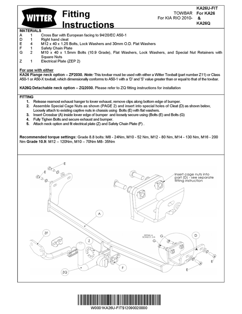
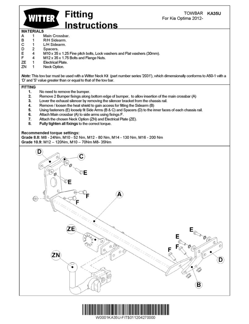
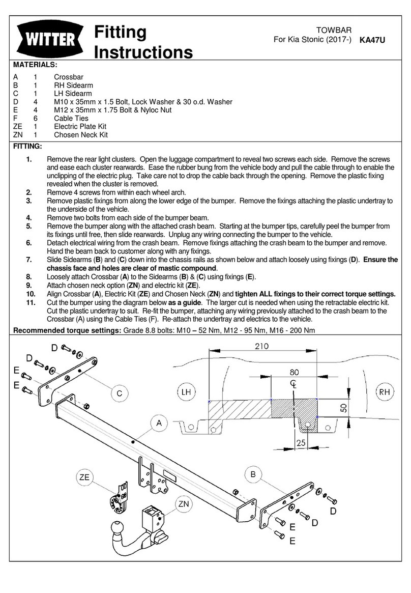
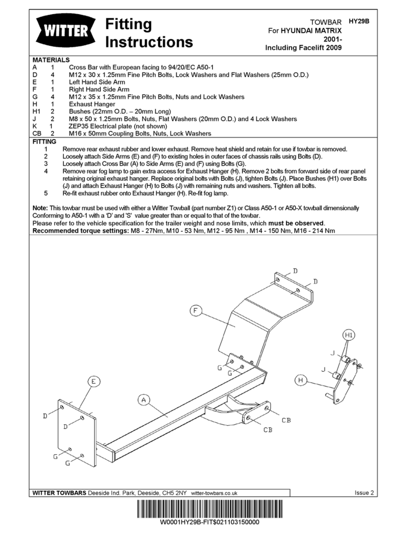
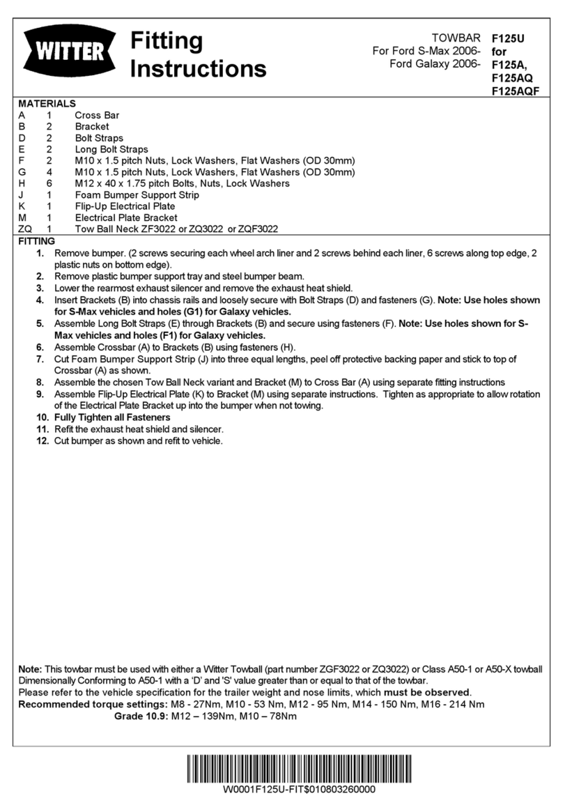
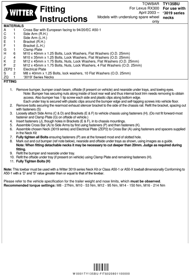
MATERIALS:
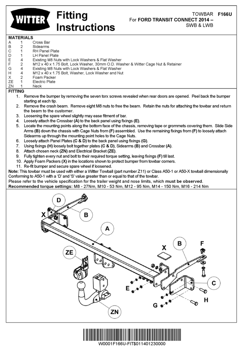
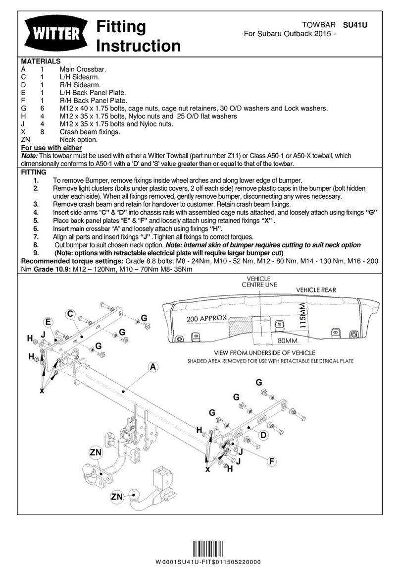
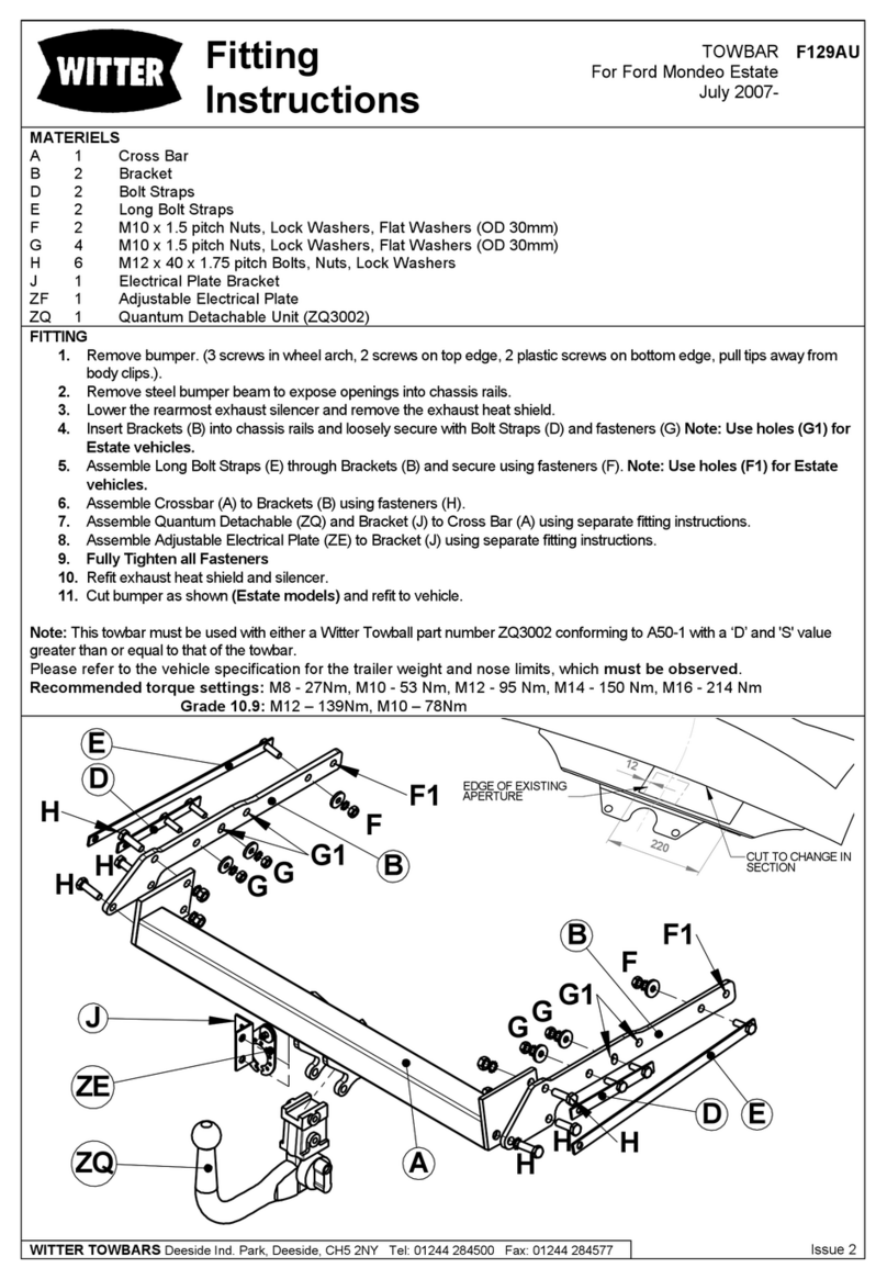
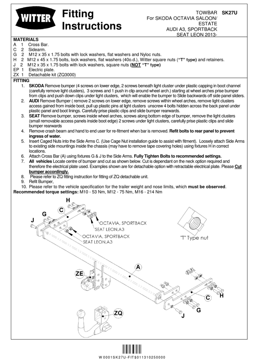
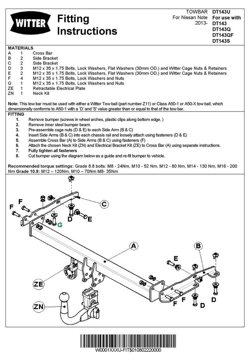
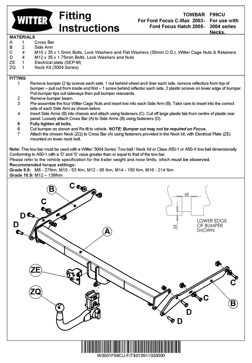
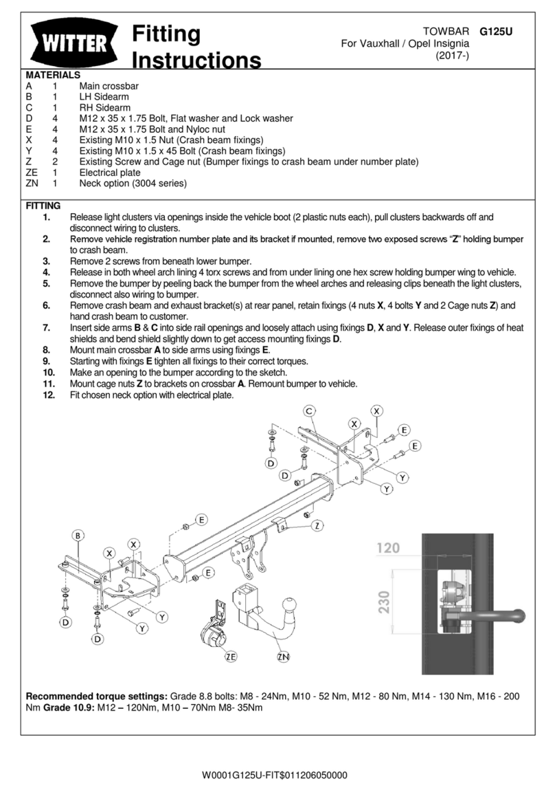
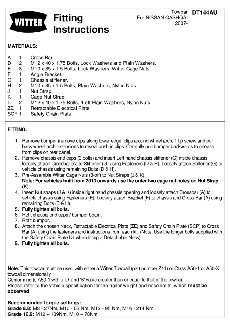
A 1 Cross Bar
B 1 Side Bracket
C 1 Side Bracket
D 2 Spacer
E 2 Witter Cage Nut Carrier
F 4 M10 x 35 x 1.5p Bolts, Lock Washers, Witter Cage Nuts and Retainers
G 4 M12 x 30 x 1.75p Bolts, Lock Washers and Nuts
H 2 M8 x 35 x 1.25p Bolts, Lock Washers, Nuts and Plain Washers (25mm O.D.)
ZE 1 Retractable Electrical Plate
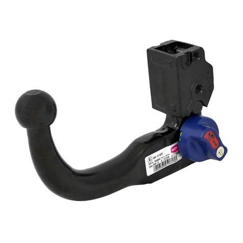
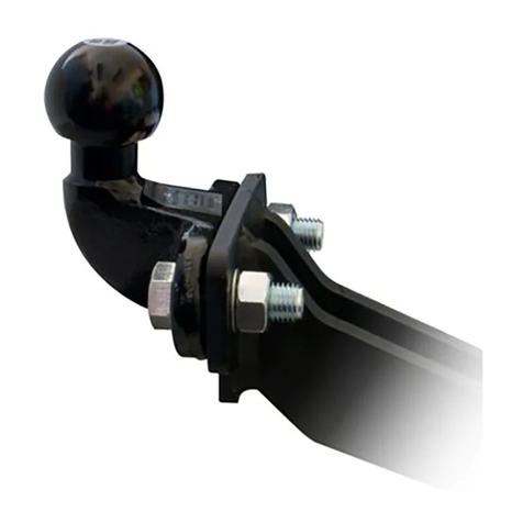
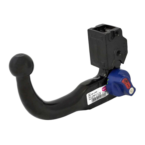
ZX 1 Chosen Neck Kit (Detachable shown for illustration purposes only)
Note: Thistowbar must be used with eithera Witter neck kit or Class A50-1 or A50-X towball, which
dimensionally conforms to A50-1 with a ‘D’ and 'S' value greater than or equal to that of the towbar.
FITTING:
1. Remove each rear light cluster (2 screwson side of moulding then pull rearwards).
2. Remove the bumper (1 Torxscrew exposed by removalof light clusters, 2 screws on bottom
edge, 2 wheel arch screws and 1 Torx tip screw in each wheel arch).
3. Remove the inner steel bumper beam (3 nutseach end).
4. Detach exhaust silencer from its mounting rubbers to gain access to underside of chassis rail.
5. Pre-assemble the Witter Cage Nuts (F) to the Cage Nut Retainers (E) using Cage NutFitting
Instructions (Take note of the orientation of Cage Nut Retainers (E)).
6. Carefully insert the Cage Nut Retainers (E) into each chassis rail and position above the
square hole in the bottom face of the chassis (Note the orientation to the corners of each
square hole).
7. Assemble each Side Bracket (B & C) to underside of each chassis rail using fasteners (F)
through the chassis' square holes (Note the orientation of each Bolt to the corners of each
square hole).
8. Assemble cross-tube to vehicle rear panel, locating over the lower bumper beam stud at each
end. Loosely secure to Side Brackets (B & C) using fasteners (G).
9. Re-fit the steel bumper beam, with Spacers (D) between the beam ends and vehicle rear
panelon outer stud mountings, and secure with original Nuts (X).
10. Complete the fitting of the steel bumper beam using fasteners (H) through the two remaining
upper mounting holes. (Use a plain washer under each nut and one under head of each M8
Bolt.)
11. Assemble the chosen Neck Kit (ZX) and Retractable Electrical Plate (ZE) to Cross Bar (A)
using fasteners provided.
12. Fullytighten all fasteners to recommended torque settings.
Recommended torque settings:
Grade 8.8 bolts: M8 - 24Nm, M10 - 52 Nm, M12 - 80 Nm, M14 - 130 Nm, M16 - 200 Nm
Grade 10.9: M12 –120Nm, M10 –70Nm M8- 35Nm
