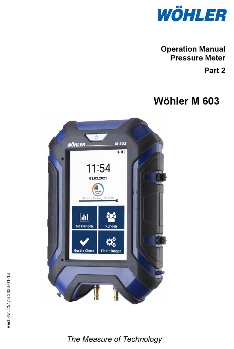
Wohler M 603 User manual

The Measure of Technology
Operating Manual
Pressure Meter
Part 1
Order No. 24811– 2023-01-18
Wöhler M 603

General information
2
Contents
1General information..............................4
1.1 Initial start-up................................................. 4
1.2 Information about this operating manual ....... 4
1.3 Notes............................................................. 4
1.4 Intended use ................................................. 4
1.5 Components.................................................. 5
1.6 Transportation............................................... 5
1.7 Disposal ........................................................ 5
1.8 Manufacturer................................................. 6
2Important information ..........................6
3Specification..........................................7
3.1 Measured values........................................... 7
3.2 Calculated values.......................................... 9
3.3 Logger function ........................................... 10
3.4 Technical data............................................. 11
4Layout and functions .........................12
4.1 Basic device ................................................ 12
4.2 Connector panel.......................................... 12
4.3 Protective covers......................................... 14
4.4 Sensors and connection components ......... 14
4.5 Touch display .............................................. 17
5Prior to use ..........................................19
5.1 Charging the battery.................................... 19
5.2 Leak tightness test ...................................... 20
6Starting the unit ..................................20
7Connecting the Wöhler M 603 to one or
more Wöhler SC 660 units..................21
7.1 Connection via the settings menu ............... 22
7.2 Connection during live measurement.......... 23
7.3 Connection prior to pressure testing with water
.................................................................... 24
8Measurements on gas pipes..............25
8.1 Stress test on gas pipes .............................. 26

General information
3
8.2 Leak tightness test on gas pipes..................30
8.3 Usability measurement on gas pipes...........34
8.3.1 Usability testing, volume flow measurement 35
8.3.2 Usability testing, pressure drop method.......44
8.4 Pipe volume measurement ..........................51
8.4.1 Pipe volume measurement, automatic........51
8.4.2 Pipe volume measurement, manual ............ 52
8.5 Regulator test ..............................................56
8.6 Regulator test ..............................................56
9Measurements on water pipes .......... 60
9.1 Leak tightness tests performed with air on
drinking water pipes.....................................60
9.1.1 Preparations for the measurement ..............61
9.2 Stress tests performed with air on drinking
water pipes .................................................. 65
9.3 Pressure testing with water on water pipes . 71
9.4 Leak tightness testing of wastewater pipes in
accordance with DIN EN 1610..................... 75
9.4.1 Sensors and connection components..........75
9.4.2 Operating principle.......................................75
9.4.3 Sealing the pipe section............................... 76
9.4.4 Presets ........................................................82
9.4.5 Measurement............................................... 84
10 Live measurement ..............................89
11 Pipe location ....................................... 92
11.1.1 Preparations ................................................93
11.1.2 Pipe location ................................................ 95

General information
4
1 General information
1.1 Initial start-up
Fig.
1: Connector panel on the bottom of
the unit
•If the unit cannot be switched on, activate the
battery before using it for the first time by
pushing the lock switch to the right with a
pointed object.
1.2 Information about this
operating manual
This operating manual enables you to work safely
with the Wöhler M 603. Keep this manual in a safe
place so you can refer to it when needed.
The Wöhler M 603 Pressure Meter is intended to
be used solely by trained professionals and must
only be used for its intended purpose.
Liability is excluded for any damages caused by
failure to comply with this manual.
1.3 Notes
WARNING!
Failure to follow this warning can result in injury or
death.
ATTENTION!
Failure to follow this information can result in per-
manent damage to the unit.
NOTE!
Important information
1.4 Intended use
This meter can be used to measure differential
pressure, absolute pressure, flow speed, tempera-
ture, and humidity. It is designed for the following
purposes in particular:
Stress testing and leak testing in accordance with
the German Gas Installations Directive (TRGI
2018 - G 600)
Measurement of leakage rate in accordance with

General information
5
the German Gas Installations Directive (TRGI
2018 - G 600)
Measurement of flow pressure, installation pres-
sure, standing pressure, jet pressure
1.5 Components
Product
Items supplied
Wöhler M 603
Pressure meter
Control report
Measuring hose (1.7 m) with
quick-release connector
USB A / USB C cable
USB power supply unit
1.6 Transportation
ATTENTION!
The unit can be damaged if it is not transported
correctly.
To prevent damage to the unit, always transport it
in the carrying case provided. The pressure con-
nectors must be protected using the protective
cap.
The case is included with the product and can
also be bought separately.
1.7 Disposal
Electronic equipment does not belong in normal
domestic waste and must be disposed of in ac-
cordance with the applicable regulations.
Defective batteries removed from the unit can be
returned to our company or to public battery dis-
posal and recycling points, or to places where
new batteries are sold.

Important information
6
1.8 Manufacturer
Wöhler Technik GmbH
Wöhler-Platz 1
D-33181 Bad Wünnenberg
Tel.: +49 2953 73-100
Fax: +49 2953 73-250
E-mail: info@woehler-international.com
2 Important information
WARNING!
Due to the compressibility of gases, for technical safety reasons the relevant accident
prevention regulations (Germany: “Arbeiten an Gasanlagen” / Work on Gas Systems
and Equipment) and the set of rules “Technische Regeln für Gasinstallationen DVGW-
TRGI” (Technical Rules for Gas Installations issued by the German Association for Gas
and Water) must be complied with during all pressure tests with air or inert gas.

Specification
7
3 Specification
3.1 Measured values
Differential pressure measurement
(temperature-compensated piezo
bridge)
Description
Reading
Measuring range
± 3,000 hPa
Permissible overload
± 3,200 hPa
Accuracy
< 3% of the measured
value; in the range < ±
2 hPa better than ±
0.06 hPa
Resolution
0.01 Pa in the range
from
–210 hPa to
+210 hPa,
otherwise 0.1 hPa
Leakage amount (usability meas-
urement)
Description
Reading
Measuring range
0.0 l/h to 10.0 l/h, test-
ed up to 8 l/h
Accuracy
± 0.2 l/h
in the range from 0 to
4 l/h, otherwise 5% of
the measured value
Resolution
0.1 l/h
Internal temperature measurement
Description
Reading
Measuring range
-20°C to 60°C
Accuracy
< ± 1°C
Resolution
0.1°C

Specification
8
External temperature measure-
ment
(optional, e.g. with a temperature
clamp probe or surface tempera-
ture sensor)
Description
Reading
Measuring range
2 channels, -20.0°C to
+800.0°C
Accuracy
< ± 1°C in the range from
-20°C to 67°C,
otherwise 1.5% of the
measured value,
in acc. with EN 50379-1
Resolution
0.1°C
Humidity measurement
Description
Reading
Measuring range
0% to 100% RH (relative
humidity), non-condensing
Accuracy
± 5% RH
Resolution
0.1% RH
Response time
Up to 180 min.
Absolute pressure
Description
Reading
Measuring range
300 hPa to 1100 hPa
Accuracy
± 2 hPa
Resolution
0.1 hPa

Specification
9
3.2 Calculated values
Calculated
parameter
Calculation
Pressure units
Conversion to hPa, Pa,
mmH2O, PSI, inwc, bar, mbar
in accordance with the gen-
erally accepted conversion
guidelines.
Temperature
units
Conversion from °C to °F in
accordance with the general-
ly accepted conversion
guidelines.
Pipe volumes
Automatic from 0.0 to 1000.0
l
Calculated
parameter
Calculation
Leakage rate
Fully-automatic (class V): 0.0
l/h to 10.0 l/h
Gas leakage amount based
on the measured pressure
difference under simultane-
ous supply of a defined vol-
ume to maintain constant
pressure
in accordance with DVGW-
TRGI worksheet G 600 in l/h.

Specification
10
3.3 Logger function
Description
Reading
Scope
9999 measurements,
each with measured
values for pressure and
humidity, as well as
three measured val-
ues for temperature
(with external sensors
connected) with freely
selectable scanning
intervals ranging from
1 second to 24 h can
be saved in the inter-
nal memory.
USB data transmis-
sion
Online data, perma-
nent, already during
registration
Bluetooth data trans-
mission
Selectable scanning
intervals
Intervals can be freely
chosen in the range
from 1 second to 24 h
IMPORTANT!
For recordings that take a long time we recom-
mend connecting the unit to the mains.

Specification
11
3.4 Technical data
Description
Reading
Display
5”
Power supply
Lithium-ion rechargeable battery 3.7 V, 6700 mAh,
charged via USB
Battery life: approx. 17 h (depending on the operating sta-
tus and brightness of the display)
Charging time: approx. 7 h
Battery charging cy-
cles
After 500 charging cycles at least 70% of the battery's ca-
pacity should still be available.
Storage temperature
-20°C to + 50°C
Operating temperature
+5°C to 40°C to ensure accuracy is within the specified
limits
Weight
700 g (fully equipped)
Dimensions
160 x 110 x 45 mm
Data exchange
USB C to the PC
Bluetooth to Smart Connect sensors and to the PC
Infrared to the printer

Layout and functions
12
4 Layout and functions
4.1 Basic device
Fig. 2: Wöhler M 603 Pressure Meter
4.2 Connector panel
Fig. 3: Wöhler M 603 Pressure Meter: connector panel
1
3
2
4
7
8
7
6
8
5
9
10
11
11

Layout and functions
13
Number
Function
1
ON/OFF button
2
USB C port / charging connection
3
Color display
4
Fastening lugs for carrying strap
5
Connector panel
6
Gas bellows connection (for usability testing with gas)
7 Pressure connection
(+)
Main connection for measurement of gas leakage
amount
8 Pressure connection (--
)
Reference connection for differential pressure meas-
urement
9, 10
Standard plug connection for temperature sensors
NiCr-Ni (type “K”)
11
Diffusion openings for internal registration of humidity
and temperature in the room. The integrated temperature
measurement also serves for temperature compensation
of the pressure sensor.

Layout and functions
14
4.3 Protective covers
Fig.
4: Protective cover for pressure
connections; the protective plugs are
marked with an arrow
The display is protected with a removable perspex
cover.
The pressure and temperature connections are
protected with a removable protective cover. This
contains two protective plugs (one of which is a
replacement plug) for the USB C port.
•
Insert a protective plug in the USB C port if no
USB cable is connected.
4.4 Sensors and connection components
Fig.
5: Connection of the Wöhler M 603
for automatic usability measurement
with filled gas bellows
Gas bellows connection for usability measurement
with gas.
NOTE!
Refer to and comply with accident prevention regu-
lation BGR 500, section 2.31 “Work on gas pipes.”
Fig.
6: Gas bellows connection
•Connect the gas bellows at the opening be-
tween the two pressure connections.

Layout and functions
15
Fig.
7: Connection fittings for manual
inflation
Connection fittings for performance of a stress test
(manually)
Connections of the Wöhler leak tightness testing
set for gas pipes:
1 Valve block
2 Connecting hose to the pressure meter
3 Connecting hose to the air pump
4 Connecting hose to the gas pipe
Fig.
8: Connections for differential pres-
sure measurement on the gas fan bur
n-
er
Connections for differential pressure measurement
on the gas fan burner:
NOTE!
The following are required: a measuring hose with
a
dia. of 3.5 mm / length of 1.5 m and 2x T-
connectors with a dia. of 4 mm
•
Split the measuring hose, and cut a 10 cm
length of hose from each of the two halves.
•
Push the longer hose sections onto the middle
piece of the T-connector and each of the
shorter hose sections onto the side of the rele-
vant T-connector that is facing outwards.
1
2
3
4

Layout and functions
16
Fig.
9: Wöhler M 603 connected to the
gas fan burner (for differential pressure
measurement)
•Remove the connecting hoses from the burner
and connect the free connection of the T-piece
in each case.
•
Then connect the 10 cm hose sections to the
burner connection.
•
Now switch on the Wöhler M 603 and read off
the differential pressure in the live measure-
ment (see part 2 of the operating manual).
Fig.
10: Connection of a temperature
clamp probe
Connection of temperature sensors or temperature
clamp probes:
Two temperature sensors or temperature clamp
probes of type “K” can be connected at the same
time.
Fi
g. 11: Connector panel with sockets
for temperature connectors
Insert the connectors of the temperature clamp
probes into the temperature sockets of the Wöhler
M 603.
On the display, the temperature value measured
via the left-hand socket is displayed as T1 and the
temperature value measured via the right-hand
socket as T2.
NOTE!
Any thermocouple of type “K” can be connected via
the plug connections.
T1
T2

Layout and functions
17
4.5 Touch display
Active buttons have a blue or white background.
Inactive butto
ns have a gray background.
If a bar can be seen on the right
-hand edge of the
display, this means that you can also scroll the di
s-
play by dragging it up or down with your finger.
Header: Bluetooth status, time, battery status,
measurement
Blue field “Differential pr.”: Tap the field to zero
the pressure sensor.
Blue buttons in the left-hand column: Tap the
field to see information about the measuring re-
quirements of DVGW TRGI.
White buttons in the right-hand column: Tap the
button to select and/or make individual adjust-
ments.
Play button, footer: Tap the play button to go to
the next measuring step (in this example: “Start
measurement”).
Skip button, footer: If a skip button is displayed in
the footer of a measurement screen, the user can
tap the s
kip button to skip the current measuring
step before it is finished, e.g. before the end of the
stabilization phase.
NOTE!
In this case the measurement will not meet the re-
quirements of the applicable standards.
Exit button, footer: Tap the exit button to end a
measurement before the specified measuring time
has elapsed.
Fig. 12: Touch display of the Wöhler M
603
– example of active/inactive but-
tons and measurement displays

Layout and functions
18
Bluetooth symbols in the header
NOTE!
The Bluetooth function can be enabled and disa-
bled in the settings menu – refer to part 2 of the
operating manual.
Bluetooth disabled
Searching for Smart Connect sensor
Bluetooth connection established
Battery charge indicator in the header
Battery is fully charged
Battery is completely empty
Battery is being charged

Prior to use
19
5 Prior to use
5.1 Charging the battery
NOTE!
The battery is permanently installed in the device
and cannot be removed by the operator.
When the unit is switched on, the battery charge
status is indicated at the top right of the display.
When the battery is fully charged, the battery icon
is completely filled. The less the battery icon is
filled, the lower the battery voltage. If the battery is
nearly empty then the background lighting will be
dimmed. In this case you should finish the meas-
urement as quickly as possible.
•
To charge the battery, connect the unit to the
power supply using the USB C charging de-
vice supplied with it.
•
The ON/OFF button flashes red during the
charging process.
NOTE!
If the battery is completely empty it will take
around 7 hours to charge. Measurements can be
performed while charging is in progress. In this
case the charging time will be extended.
Once the charging process has been completed
the ON/OFF button lights up red continuously.
WARNING!
Risk of death due to electric shock!
Never touch the mains plug with wet hands.
Keep the power supply away from moisture.
Never pull out the power supply from the mains
socket by the cable, as it could break.
Only operate the power supply if the voltage indi-
cated on the type plate matches the voltage sup-
plied from the mains socket.
Proceed as follows to charge the battery:
•Connect the corresponding power supply to

Starting the unit
20
the unit via the USB C charging port (see Fig.
1) and then connect the power supply to the
mains.
5.2 Leak tightness test
•Perform a leak tightness test in accordance
with part 2 of the operating manual, section
4.2.
6 Starting the unit
WARNING!
When performing measurements with the Wöhler
Pressure Meter, always refer to the relevant acci-
dent prevention regulations (Germany: “Arbeiten
an Gasanlagen” / Work on Gas Systems and
Equipment) and the set of rules “Technische Re-
geln für Gasinstallationen DVGW-TRGI” (Tech-
nical Rules for Gas Installations issued by the
German Association for Gas and Water).
CAUTION!
Never leave the unit lying around unprotected.
To avoid damage, when performing measure-
ments always
•
hold the unit in your hands,
or
•
use the magnets on the rear of the unit to
attach it to the installation.
Switching on
Fig.
13: Switching ON/OFF
CAUTION!
Whenever you use the unit, always start by visual-
ly inspecting it to make sure that everything is in
proper working order.
•
Switching the unit ON: Press and hold the
ON/OFF button for 2 seconds.
Other manuals for M 603
1
Table of contents
Other Wohler Measuring Instrument manuals

Wohler
Wohler Pandora User manual

Wohler
Wohler VAMP AC-3/M User manual

Wohler
Wohler SP 22 User manual

Wohler
Wohler A 400 User manual

Wohler
Wohler DM 2000 User manual

Wohler
Wohler iVAM2-2 User manual

Wohler
Wohler A 550 User manual

Wohler
Wohler IQ 300 User manual

Wohler
Wohler CD 210 User manual

Wohler
Wohler VE User manual

Wohler
Wohler RF 220 User manual

Wohler
Wohler AMP2-16V Series User manual

Wohler
Wohler FA 320 User manual

Wohler
Wohler LM25 Analog Series User manual

Wohler
Wohler HF 300 User manual

Wohler
Wohler A 450 User manual

Wohler
Wohler Smart Connect SC 660 User manual

Wohler
Wohler BC 600 User manual

Wohler
Wohler FA 320 User manual

Wohler
Wohler 3343 User manual