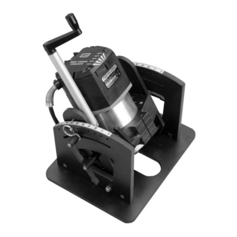
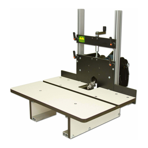
manuals.online logo
Brands
  1. Home
  2. •
  3. Brands
  4. •
  5. Woodhaven
  6. •
  7. Tools
  8. •
  9. Woodhaven Angle-Ease 1470 User manual

Woodhaven Angle-Ease 1470 User manual

1470 & 1472 Angle-Ease™
or
576 & 577 Angle-Ease™
Owners Manual
U.S. Patent #6,742,558
Please Read Carefully!
Additional Parts List:
Parts listed below are not shown in the hardware
drawings. Refer to photos in the instructions:
Part Description Quantity
1470AS Side/Arm Assembly, pair . . . . . . . . . . . . . . . . 1
1470C 7-1/2” Double Track. . . . . . . . . . . . . . . . . . . . . 2
1475 Height Adjuster (in it’s own package) . . . . . 1
In addition, you will get ONE of the motor
blocks and plates below, depending on the
Angle-Ease model you purchased:
1470B 3.5” Motor Block. . . . . . . . . . . . . . . . . . . . . . . . 1
1472B 4.2” Motor Block . . . . . . . . . . . . . . . . . . . . . . . 1
1470P Angle Ease Router Table Plate . . . . . . . . . . . 1
576P Horizontal Table Angle-Ease Plate. . . . . . . . 1
The Angle-Ease fits
motors from these routers:
Router Model
FITS 3.5”
ANGLE-
EASE
FITS 4.2”
ANGLE-
EASE
Porter Cable 7518 No Yes
Milwaukee 5625 No W/ Shim
Porter Cable 892 Yes W/ Adapter R1
Porter Cable 690 Yes W/ Adapter R1
DeWalt 616/618 Yes W/ Adapter R1
Bosch 1617/1618 Yes W/ Adapter R1
Makita RF1100 No W/ Adapter R2
Hitachi M12VC No W/ Adapter R3
Ridgid 2900/2930 No W/ Adapter R4
Part# Description Qty.
MF015 1” Screw 6
Part# Description Qty.
5864 Knob - 1-5/8” 2
Part# Description Qty.
WN001 Nylon washer 4
Part# Description Qty.
WB002 Washer 4
Part# Description Qty.
5863 Knob - 1-1/8” 2
Part# Description Qty.
Ringpin1 Pin 2
Part# Description Qty.
5791B Barrel Nut 3
Part# Description Qty.
5760B Oval Nut 12
Part# Description Qty.
MF010 3/4" Screw 8
Part# Description Qty.
BUSH002 1/4" Spacer 4
1
BEFORE BEGINNING
Identify and verify that you have all the parts listed.
Read the instructions at least once, familiarizing yourself with
the parts, before beginning assembly. You’ll need two 7/16"
wrenches, a #3 Phillips screwdriver and a flat blade screwdriver.
ASSEMBLY
Find the side/arm assembly (1470AS) that has the
arm with the squared-off corner. Get the adjuster arm
(1475A1) from the 1475 Height Adjuster package and
attach it to the squared-off arm as shown, using two 3/4"
screws (MF010). Pivot the arm as necessary to access the
lower mounting hole in the arm. Set the remaining height
adjuster parts and hardware aside until later. See fig. 1.
Take both side/arm assemblies and align the pointer
in the arm with the 10º mark on the scale on the top of
the side. Insert a pin (Ringpin1) through the 10º hole
in the side and into the hole in the arm. See fig. 2.
Install a washer (WB002) and a nylon washer (WN001)
on the stud of the knobs (5863). Slide another nylon washer
(WN001) between the arm and side. A credit card can help
position the washer. The washer must be aligned with the
curved slot in the side and the threaded hole in the arm.
Insert the stud of the knob thru the curved slot in the side,
screwing it into the arm, then tighten the knob. See fig. 3.
Insert 1" screws (MF015) thru the three countersunk
holes in each side and start an oval nut (5760B - flat
side first) on each screw. Slide a 7.5" deluxe track
(1470C) on to the oval nuts on each Side. Center the
deluxe track on the side, check the side for square on
a flat surface and tighten the screws. See fig. 4.
Remove the pin from each arm, loosen the
handle and rotate the arm to the 0º mark on the side,
then reinstall the pin and tighten the knob.
ATTACH ROUTER BLOCK
Set the router block on end with the clamping
knob in the router block (1470B or 1472B) facing the
bottom. Insert a barrel nut (5791B) in the hole in the
face of the router block near the end. Use a flat blade
screwdriver to align the threaded hole in the barrel nut
with the cross hole in the router block. See fig. 5.
1
2
4
3
Pin removed
for clarity
5
2
Install a washer (WB002) and two 1/4" spacers
(BUSH002) on the knobs (5864). Using the side/arm assembly
with the height adjuster arm attached to it, set the arm in the
groove in the router block. Install the ratchet handle thru the
slot in the arm, screwing it into the barrel nut. Slide the router
block as far down on the arm as possible (away from the height
adjuster arm) and tighten the knob. Flip the assembly over
and connect the remaining side/arm assembly to the opposite
side of the router block in the same manner. See fig. 5 & 6
ATTACH ASSEMBLY TO PLATE
Insert 3/4" screws (MF010) thru the six countersunk
holes in the router plate (1470P or 576P) and start oval
nuts (5760B - flat side first) on the ends of the screws.
Line the oval nuts up with the T-slot in the double
tracks and slide the assembly on to the oval nuts.
If you have the 1470P plate, position the assembly so
the back edge of the sides are 11/16" from the edge of the
plate and tighten the screws. The opening in the router block
should be over the bit opening in the router plate. See fig. 7.
If you have the 576P plate, position the assembly so the
back edge of the sides are flush with the edge of the plate and
tighten the screws. The opening in the router block should
be over the bit opening in the router plate. See fig. 7.
INSTALL HEIGHT ADJUSTER
Install a barrel nut (5791B) in the hole in the front of
the router block. Use a flat blade screwdriver to align the
threaded hole in the barrel nut with the cross hole in the
router block. Get the 1475 Height Adjuster package. Spread
the two nylon washers on the threaded rod of the height
adjuster (1475B) apart enough so the rod slips in the groove
in the adjuster arm (installed earlier) and the washers are on
each side of it. Continue screwing the threaded rod into the
barrel nut until the nylon washer on the top of the adjuster
arm is snug against the top of the adjuster arm. See fig. 8.
6
7
8
3
10
Place the arm plate (1475A2) with it’s groove covering
the threaded rod and fasten it to the adjuster arm using
the 3/4" screws (5771B). Align the top and bottom edge
of both parts before tightening the screws. See fig. 9.
Adjust the two nuts on the threaded rod, along with
the washers, against the underside of the adjuster arm.
Tighten the nuts against each other when you have adjusted
the up/down slop out of the height adjuster. See fig. 9.
ROUTER INSTALLATION
Loosen the clamp handle in the router block and insert
your router in the router block so the end of the motor is flush
with the router block, or protruding out past it.. The router
motor should always be fully inserted in the router block!
Never insert a router motor partially in the router block! The
router motor can be repositioned anywhere in the motor block as
long as it is completely in the motor block at all times. Tighten
the clamp handle just enough to hold the router motor. Do not
over-tighten or you may damage your router. See fig. 10.
ANGLE SETTINGS
There are pin settings at 0, 5, 10, 15, 20, 22-1/2, 25, 30,
35, 40 & 45 degrees, or you can set your desired angle using the
scale on top of the sides as a guide. To set an angle, remove the
two pins (if used), loosen the two angle adjustment knobs and
pivot the router to the desired angle. Replace the pins (if the
angle is one of the pin settings above) and tighten the knobs.
Angle settings other than those provided can
be set using a drafting square or bevel gauge placed
between the plate and the face of the router block.
HEIGHT ADJUSTMENT
IMPORTANT!! Loosen the height knob nearest the
Height Adjuster just 1/4 to 1/2 of a turn and loosen the
opposite height knob 2 full turns. Retighten the knob nearest
the Height Adjuster first, then retighten opposite knob.
Turn the crank handle on the Height Adjuster to
move the router up or down. If you cannot achieve the
desired height, you may have to reposition the router in
the router block (see router installation section above).
USING THE ANGLE EASE
There are two ratchet knobs for locking the height and
two for locking the angle. Perform one of these adjustments
at a time instead of attempting both adjustments at the same
time. Make sure your bit is locked securely in the router
collet and that all knobs are tightened securely before using.
Depending on your table opening size, you may have to
set the Angle-Ease at 0º degrees to insert it in your router table.
To reduce the risk of injury we recommend that
you tilt the cutter into the fence (or table) hiding more
of the cutter compared to tilting the cutter away from
the fence (or table) and exposing more of the cutter.
©Copyright WOODHAVEN INC. 9/18/07
(800)344-6657 or WWW.WOODHAVEN.COM
9

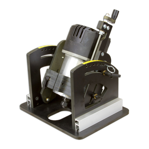
This manual suits for next models

3

Other Woodhaven Tools manuals

Woodhaven 3000 User manual

Woodhaven

Woodhaven 3000 User manual

Woodhaven Angle Ease 1425 User manual

Woodhaven

Woodhaven Angle Ease 1425 User manual

Woodhaven 6002 User manual

Woodhaven

Woodhaven 6002 User manual

Woodhaven 3210 User manual

Woodhaven

Woodhaven 3210 User manual

Woodhaven HD Panel Master 5432 User manual

Woodhaven

Woodhaven HD Panel Master 5432 User manual

Woodhaven Angle-Ease 1470 User manual

Woodhaven

Woodhaven Angle-Ease 1470 User manual

Woodhaven 8628 User manual

Woodhaven

Woodhaven 8628 User manual

Woodhaven 6012 User manual

Woodhaven

Woodhaven 6012 User manual

Woodhaven 8625 User manual

Woodhaven

Woodhaven 8625 User manual

Woodhaven 7902 User manual

Woodhaven

Woodhaven 7902 User manual

Woodhaven 3000 User manual

Woodhaven

Woodhaven 3000 User manual

Woodhaven 5435 User manual

Woodhaven

Woodhaven 5435 User manual

Woodhaven 204 User manual

Woodhaven

Woodhaven 204 User manual

Woodhaven 7500 User manual

Woodhaven

Woodhaven 7500 User manual

Woodhaven 8395 User manual

Woodhaven

Woodhaven 8395 User manual

Woodhaven 8615 User manual

Woodhaven

Woodhaven 8615 User manual

Woodhaven 5432 User manual

Woodhaven

Woodhaven 5432 User manual

Woodhaven 8715 User manual

Woodhaven

Woodhaven 8715 User manual

Woodhaven EZ Lift 1429 User manual

Woodhaven

Woodhaven EZ Lift 1429 User manual

Woodhaven 8610 User manual

Woodhaven

Woodhaven 8610 User manual

Popular Tools manuals by other brands

dosatron D14 Series instructions

dosatron

dosatron D14 Series instructions

Blacoh XPX Operation instructions

Blacoh

Blacoh XPX Operation instructions

Facom Y.107CPB Original instructions

Facom

Facom Y.107CPB Original instructions

TOPMAQ HAGD2950 instruction manual

TOPMAQ

TOPMAQ HAGD2950 instruction manual

Emerson Greenlee LS50FLEXCFM manual

Emerson

Emerson Greenlee LS50FLEXCFM manual

Graco 750 Series instructions

Graco

Graco 750 Series instructions

DeWalt DE0734 instructions

DeWalt

DeWalt DE0734 instructions

Apogee 07696 manual

Apogee

Apogee 07696 manual

Cessna 172 Skyhawk 1972 owner's manual

Cessna

Cessna 172 Skyhawk 1972 owner's manual

Flexzilla L8305FZ Parts and technical service guide

Flexzilla

Flexzilla L8305FZ Parts and technical service guide

Sealey VSE5312.V2 manual

Sealey

Sealey VSE5312.V2 manual

Baileigh Industrial BV-4I Operator's manual

Baileigh Industrial

Baileigh Industrial BV-4I Operator's manual

Eastwood 32499 instructions

Eastwood

Eastwood 32499 instructions

Josef Kihlberg a.560PN manual

Josef Kihlberg

Josef Kihlberg a.560PN manual

Max Twintier RB441T Instruction manual and safety instructions

Max

Max Twintier RB441T Instruction manual and safety instructions

Sumake ST-2320/R Installation & operator's instruction manual

Sumake

Sumake ST-2320/R Installation & operator's instruction manual

Hazet 842 AG-1 manual

Hazet

Hazet 842 AG-1 manual

ULTIMATE SPEED 383687 2110 Operation and safety notes

ULTIMATE SPEED

ULTIMATE SPEED 383687 2110 Operation and safety notes

manuals.online logo
manuals.online logoBrands
  • About & Mission
  • Contact us
  • Privacy Policy
  • Terms and Conditions

Copyright 2025 Manuals.Online. All Rights Reserved.