manuals.online logo
Brands
  1. Home
  2. •
  3. Brands
  4. •
  5. Woosh
  6. •
  7. Bicycle
  8. •
  9. Woosh Big Bear Assembly instructions

Woosh Big Bear Assembly instructions

Other manuals for Big Bear

1

Other Woosh Bicycle manuals

Woosh Rio FB User manual

Woosh

Woosh Rio FB User manual

Woosh Faro User manual

Woosh

Woosh Faro User manual

Woosh Big Bear User manual

Woosh

Woosh Big Bear User manual

Woosh Zephyr 2017 User manual

Woosh

Woosh Zephyr 2017 User manual

Woosh Gallego User manual

Woosh

Woosh Gallego User manual

Woosh Sirocco Big Bear User manual

Woosh

Woosh Sirocco Big Bear User manual

Woosh Sirocco 2 User manual

Woosh

Woosh Sirocco 2 User manual

Woosh Zephyr User manual

Woosh

Woosh Zephyr User manual

Woosh Sundowner User manual

Woosh

Woosh Sundowner User manual

Woosh Zephyr User manual

Woosh

Woosh Zephyr User manual

Woosh Aspen X User manual

Woosh

Woosh Aspen X User manual

Woosh Aspen X User manual

Woosh

Woosh Aspen X User manual

Woosh Krieger User manual

Woosh

Woosh Krieger User manual

Woosh Krieger 2017 User manual

Woosh

Woosh Krieger 2017 User manual

Woosh Gran Camino User manual

Woosh

Woosh Gran Camino User manual

Woosh Sirocco Sport User manual

Woosh

Woosh Sirocco Sport User manual

Popular Bicycle manuals by other brands

Grace ONE manual

Grace

Grace ONE manual

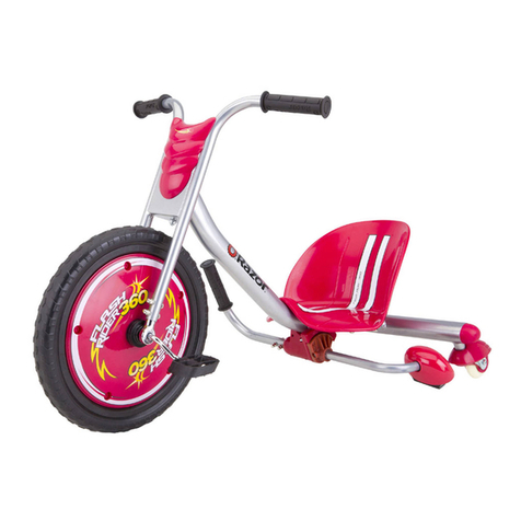
Razor FLASHRIDER 360 user manual

Razor

Razor FLASHRIDER 360 user manual

TAUBIK SOHO 2.0 user manual

TAUBIK

TAUBIK SOHO 2.0 user manual

Oxybul FREEbul 331067 manual

Oxybul

Oxybul FREEbul 331067 manual

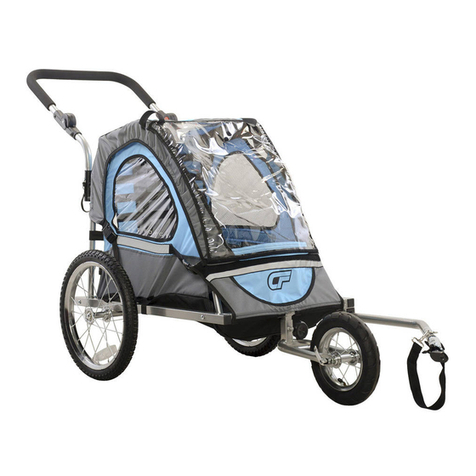
Cycle Force Group BICYCLE BABY TRAILER & JOGGER Assembly instructions

Cycle Force Group

Cycle Force Group BICYCLE BABY TRAILER & JOGGER Assembly instructions

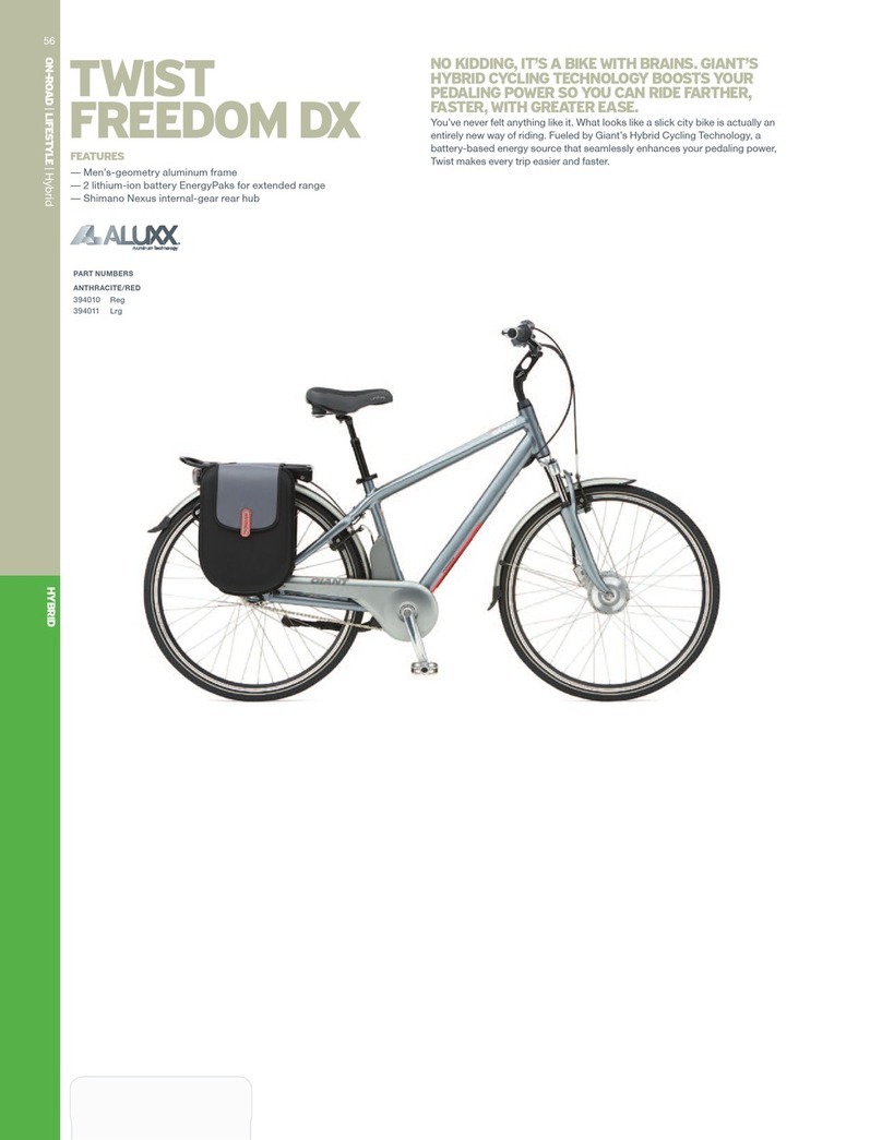
Giant TWIST FREEDOM DX datasheet

Giant

Giant TWIST FREEDOM DX datasheet

RAMBO R1000X2M-FF-BFD manual

RAMBO

RAMBO R1000X2M-FF-BFD manual

Vermeiren SAFARI Maintenance manual

Vermeiren

Vermeiren SAFARI Maintenance manual

Velec A2/36V owner's manual

Velec

Velec A2/36V owner's manual

Cervélo S3 2019 Assembly manual

Cervélo

Cervélo S3 2019 Assembly manual

Festo EGSC-BS-KF Instructions & Operating

Festo

Festo EGSC-BS-KF Instructions & Operating

Gio Electric H1 Volt owner's manual

Gio Electric

Gio Electric H1 Volt owner's manual

Huka orthros manual

Huka

Huka orthros manual

DAHON CIAO - 2009 manual

DAHON

DAHON CIAO - 2009 manual

Aprimatic ONDA 500 Installation, use and maintenance instructions

Aprimatic

Aprimatic ONDA 500 Installation, use and maintenance instructions

Greyp G6 Series user manual

Greyp

Greyp G6 Series user manual

Babboe Carve-E user manual

Babboe

Babboe Carve-E user manual

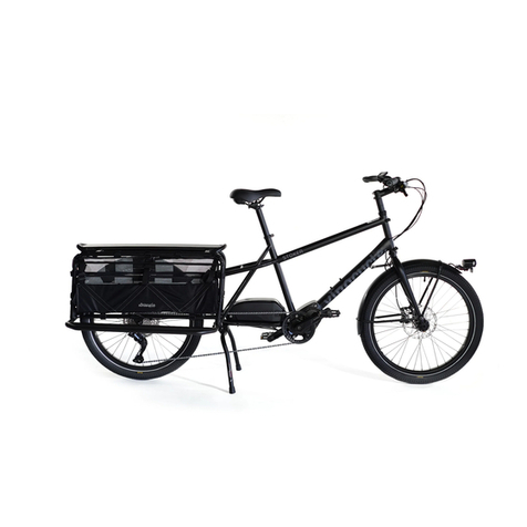
Xtracycle Stoker 2021 Assembly manual

Xtracycle

Xtracycle Stoker 2021 Assembly manual

manuals.online logo
manuals.online logoBrands
  • About & Mission
  • Contact us
  • Privacy Policy
  • Terms and Conditions

Copyright 2025 Manuals.Online. All Rights Reserved.

1
Sales: 01702 435566 — Support: 01702 684444 — E-mail: support@wooshbikes co uk
Important: For your own safety you must read this man-
ual before attempting to fit any part of the motor kit to your
bike. You must also ensure that you fit the kit in strict ac-
cordance with the instructions in this manual.
Big Bear
Hub Kit Fitting Guide
Lishui controller + King Meter J-LCD upgrade
2
Before you start the installation of your it, please read the following:
This kit is intended to be fitted by someone who is competent and experienced at fitting electric kits to
bikes. If you are not experienced and/or lack the necessary tools to complete any of the procedures in
this manual, you should seek the advice of a professional who can fit the kit for you. If necessary, call us
on 17 2 684444 or email us at [email protected]o.uk and we will try and put you in touch with
someone in your area that has the necessary expertise to properly fit your kit. You will of course need to
pay for the technician to install your kit, these costs are not covered by Woosh Bikes.
If you intend to use the pedal-assist feature of this it, you must first ma e sure that the Pedal Assist
Disc is actually suitable for your bi e before fitting any of the other parts of this it - see Section 2 of
this manual.
Warranty Terms:
If your kit is fitted by a professional installer, it will be covered by our standard one year warranty, which
means that in the event of a failure, you would first need to have the person that installed your kit con-
firm the issue and likely cause, then you (or the installer) would need to contact us and provide us with
the details of the fault. If the issue cannot be resolved over the phone or via email, then you would need
to return the faulty part to us at your expense. We will then repair or replace the faulty part and send it
back to you at our expense. If the kit was not fitted by a professional and/or the failure that has occurred
is due to a poor or incorrect installation of the kit, the warranty will be voided.
3
1. What’s in the Box
Ensure that you have all the parts listed below before going any further, if there are any missing parts,
contact us on 17 2 435566.
The motor kit comprises of a rear wheel with hub motor, a controller, controller housing, a battery, a
charger, motor cable, modular one-cable system, pedal-assist disc and sensor, speed sensor (and magnet)
and a thumb throttle. Ensure that you have all of these items, a photo of the items is show below so you
can easily identify each of the parts. As well as the parts shown below, you will also have the motor-wheel
and battery charger.
Handlebar Grips
Motor Cable
Battery
Wheel Nuts/Bolts
Speed Sensor and Magnet
LCD Module
Cables—Modular
Pedal Assist Disc
Pedal Assist Sensor
Controller
Inline Brake Sensor (x2)
Optional
Thumb Throttle
Your kit may vary slightly from the picture above, but it should
include the same no. of components though some may differ
slightly in appearance. The inline brake sensors are not an op-
tion with this kit version.
4
2. Installation of the Pedal-Assist Disc/Sensor
It is possible to use this kit without the pedal-assist feature, if you are not going to use this feature, then
you can ignore this page and move on.
If you do intend to use the pedal-assist feature, follow the instructions below.
Before fitting any of the other components to the bike, you must ensure that the PAS disc can be fitted to
your particular bike. In some cases it may not be possible to fit this part in the way it was intended, if this
is the case, give us a call on 17 2 684444, we may be able to supply an alternate part. Do NOT continue
fitting the rest of the kit until the issue with fitting the PAS disc has been resolved.
The pedal-assist sensor (PAS) consists of two parts, these are the sensor itself and the pedal-assist disc. In
most cases you do not need to remove the crank to fit the PAS disc, simply remove the silver lock-ring
from the outer edge of the PAS disc, detach the two halves of the disc and then snap them together
around the spindle. Fit the lock-ring back in place to secure the two halves together. You will likely need
to adjust the positioning of the disc slightly and also the position of the sensor (when you come to fit it)
to suit your particular installation.
You must ensure that the disc is the correct way around on the spindle, otherwise you will find that the
motor kicks in when you pedal backwards! The correct way around assuming the disc is fitted to the left
side of the bike is with the side labelled “working surface” facing outwards away from the frame.
Mount the pedal-assist sensor in such a way that the magnets in the disc pass the end of the sensor as
the disc rotates—as shown below. You may need to change the orientation of the sensor if it does not
work the first time. The gap between sensor and disc needs to be as small as possible.
5
3. Battery
The bottle-style battery included in this kit mounts to your bike using the same bolts that you would nor-
mally use to mount a bottle holder. First you will need to unlock and then detach the battery from the
base. The base is the part that you need to attach to the frame, see photos below. Turn the key anti-
clockwise and then lift the lever and pull the battery upwards and off the base in the direction indicated
below-right.
You will need to position the base in such a way that will allow you enough clearance to be able to lift the
battery off the bike without the top tube obstructing. Once the base has been secured to the frame, fit
the battery in place and double-check that that you have enough clearance between the battery and the
top tube, and adjust the position of the base if necessary. You should then remove the battery and con-
tinue on with the installation of the kit. The battery is quite heavy and bulky and so it is easier to fit the
remaining parts without the battery in place, and then simply re-fit the battery when the kit installation is
complete.
6
4.1 Motor Wheel (Front Option)
You will need to remove the existing front wheel and swap the tyre and tube to the new motor wheel.
This is a simple process that any bike technician should be able to complete without any additional guid-
ance. If you have purchased this kit and cannot carry out one or more of the steps in this manual or do
not have the necessary tools to complete these steps, you should seek the advice of a professional who
can fit the kit for you.
You must ensure that the motor cable where it exits the spindle, points upwards (only for this kit) , see
below for photos showing the kit fitted, and the orientation of the spindle i.e. with the cable facing up.
Use the nuts and washers supplied with the kit, it may be necessary to use additional washers to allow
you to correctly line up the brake-disc within the callipers.
Once the wheel is properly installed, connect the motor cable (lining up the arrows on each connector)
and secure the motor cable to the fork leg using cable–ties.
7
5. Handlebar Components:
The throttle and display module need to be mounted to the handlebars. The installation procedure for
these parts may vary a little from bike to bike, but follow the guide below for a general overview.
The LCD module and key-pad would normally be fitted to the left side of the handlebars just to the right
of the grip. There is no need to remove the grip to fit the LCD, unless you want to rearrange the layout of
some of the other components that you may already have fitted to your handlebars. Simply remove the
two screws and then clip the LCD over the handlebars at the desired position, then re-fit the screw and
tighten to secure. It’s a similar process to secure the key-pad but there’s just a single screw.
To fit the thumb-throttle, you will need to slide the grip off the right side, loosen any of your existing com-
ponents such as the shifter, brake lever etc. and move them towards the centre a little, then slide the
throttle on and then tighten to secure it in the desired position.
Note: When fitting the throttle, you may need to replace your grips with the shorter ones supplied with
the kit if you are not able to move your existing components towards the centre a little.
Depending on the configuration of the bike, it may be more practical to mount the throttle and display in
slightly different locations or on opposite sides, you must decide which configuration suits your particular
case best.
The next step is to run the modular cable (for the LCD, throttle and optional brake cut-outs) from the
front of the bike back to the where the controller is going to be located, the location of the controller is
determined by the size of your triangle, on an 18 inch frame, you may have to mount the controller hous-
ing on the underside of the down tube. On larger frames, you can usually mount the housing on the front
face of the lower section of the seat tube. You can fit the controller in a different location if you wish, but
you must ensure that all of the cables from the various components will reach. Highlighted in RED below
are the possible routes for this cable and two possible locations for the controller.
8
5. Handlebar Components cont.
You must ensure that there is enough play in the cables so that they do not get stretched or pulled when
the handlebars are rotated.
Depending on the type of brake levers being used, you may have two unused RED connectors one the
modular cable, these connectors are used when the brake levers with built-in cut-out switches as per
those pictured on the previous page are used. If you have purchased your kit with the in-line brake cut-
out sensors, the leads from these sensors attach directly to the controller, therefore the two RED connec-
tors are not used. If you are using the in-line sensors, you MUST tape up and seal the two unused RED
connectors and you should also cable-tie them in a downward-pointing position to help protect them
from the elements.
The throttle cable and LCD connectors are colour coded and should be mated with the matching colours
on the modular cabling. There are arrows on each connector which indicate how to line them up, see
photos below.
The arrows don’t show up all that well in the photo unfortunately but you should be able to make out the
arrow on the left connector (right picture above). Ensure that the arrows line up on both sides before
pushing the connectors together, be careful with them and don’t force them or you may bend/damage
the pins. Also be sure to mate the cables with the matching coloured connectors i.e. LCD cable to the
black connector, throttle cable to the yellow connector, and brake cut-outs to the red connectors.
The modular cable will need to be cut to a length which is suitable for your installation, meaning that you
will need to fit the crimps onto the individual wires. If you are not able to fit the crimps to the cable, if
you cut the cable to the required length and then send it to us, we will fit the crimps and return it back to
you.
See the section later in the manual which details the configuration of the wires/connectors.
9
6. Fitting the Speed Sensor:
The speed sensor consists of two parts, the sensor itself and a magnet that is attached to one of the
spokes. The sensor is normally fitted at the rear, but can be mounted at the front if you prefer.
The speed sensor is mounted approximately half-way along the inside of the chain stay as shown in the
diagram below (in Red). Simply secure the sensor to the frame with cable-ties, it may be necessary to fit a
rubber spacer between the sensor and the frame to bring the sensor closer to the magnet, otherwise it
may not detect the magnet as it passes. Attach the magnet to a spoke in such a position so that as the
wheel rotates, the magnet passes just slightly rearwards of the centre of the sensor as shown below-right.
Run the cable along the chain stay as indicated in RED above, securing it with cable-ties and ensuring that
the cable is clear of the wheel/tyre, then up towards the controller (two possible locations indicated). The
cable from the speed sensor will attach to the (Red/Blue/Yellow) connector coming from the controller.
1
7. Controller Connections:
The controller has support for the following features/connections:
2x Power Connector (thicker Red lead and thicker Black lead) — connect to same colours from battery)
3x Motor Connector (thicker Green, Yellow and Blue) — connect to same colours from motor
1x Pedal Assist Sensor (Red/Blue/Black) - connect to same colours from controller
2x Brake cut-out (Red/Grey/Black) - connect to cut-out sensors with (Black/White/Red) connectors (only
for use with the in-line sensor option).
The modular cable coming from the handlebars splits and terminates into three separate leads, these are
as follows:
Large White Connector —Thumb Throttle (Purple/Grey) - connect to it’s mate (Red/Green/Black) from
controller.
Speed Sensor - connects to (Red/Blue/Yellow) connector from controller
5-Pin Connector for LCD — connects to its mate
There are several leads coming from the controller that are not used, these are (Red/Black), (Red/Grey),
(Red/Black/Purple) and one of the (Grey/Black) leads.
The controller housing is shown below, the concave side attaches to the frame.
Big Bear Controller
(LSW947-1 -2)