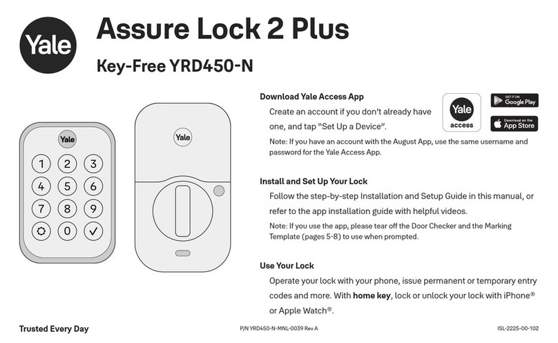
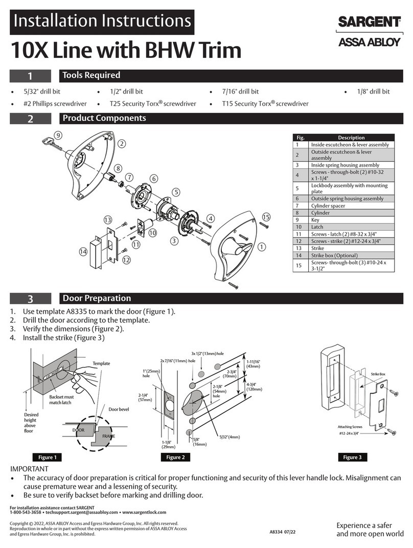
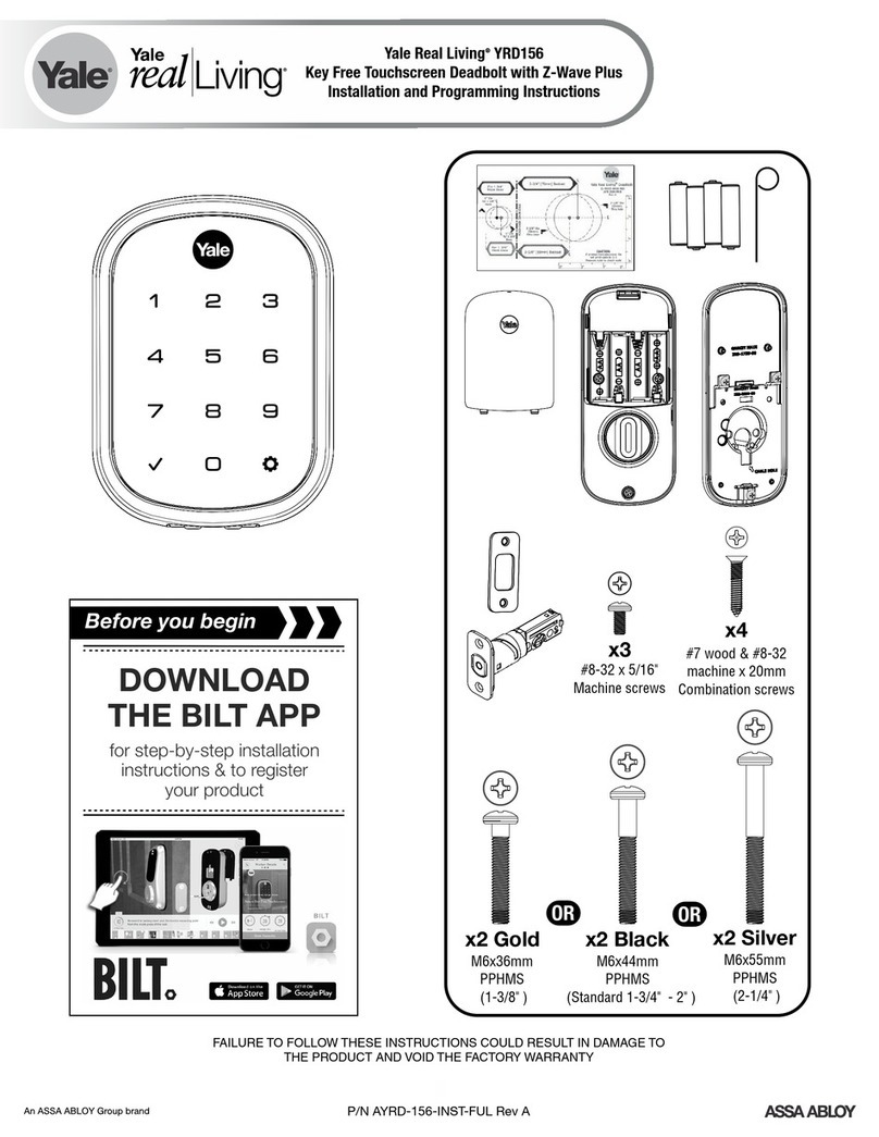
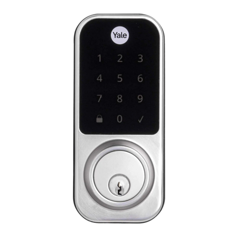
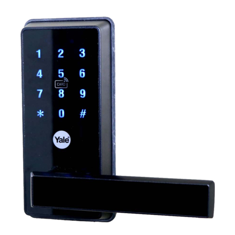
Yale Assure Lock 2 Touch User manual

P/N YRD450-KF-F Rev A
Assure Lock 2 Touch
Key-Free YRD450F
Trusted Every Day
Download Yale Access App
Create an account if you don’t already have
one, and tap “Set Up a Device”.
Note: If you have an account with the August App, use the same username and
password for the Yale Access App.
Install and Set Up Your Lock
Follow the step-by-step Installation and Setup Guide in this manual, or
refer to the app installation guide with helpful videos.
Note: If you use the app, please tear off the Door Checker and the Marking
Template (pages 58) to use when prompted.
Use Your Lock
Unlock with your fingerprint, create permanent or temporary entry
codes, set up Auto-Lock and more.
ISL222500101

P/N YRD450-KF-F Rev A
All key-free locks should only be installed on homes with more than one point of entry.

3
P/N YRD450-KF-F Rev A
Contents
In the Box 4
Door Checker 5
Marking Templates 7
Installation and Setup Guide 9
Remove Existing Deadbolt 10
Check Door Measurements 11
Make or Adjust Holes 12
Install Deadbolt Latch 13
Install Exterior Keypad 14
Install Mounting Plate 15
Attach Wire Cable to Interior Lock 16
Install Interior Lock 17
Test Thumbturn 18
Install Yale Smart Module (Optional) 19
Install DoorSense (Optional) 20
Install Batteries and Set Up with App 23
Set Up HomeKit (Optional, iOS Only) 24
Set Up Fingerprints and Entry Codes 25
Using Your Lock 26
Connecting to Your Lock 27
LED Alerts 28
Resetting Your Lock to Factory Defaults 29
Features 30
App Settings 31
Lock Operations Troubleshooting 33
Hardware Troubleshooting 35

4
P/N YRD450-KF-F Rev A
In the Box
Lock Hardware
b.
c.
d.
e.
X 4
X 4
X 2
X 2
X 2
X 2
X 2
Add-Ons
123
5 76
4
UP
1. Exterior Keypad
2. Interior Lock
3. Strike Plate
4. Adjustable Deadbolt
5. Manual
6. Reset Pin
7. Mounting Plate
8. AA Batteries
9. Screws
a. Strike Plate and Deadbolt Screws
b. Teal Screw Set B
c. Black Screw Set C
d. Silver Screw Set D
e. Optional Security Strike Plate Screws
10. DoorSense
a. Housing
b. Cover
c. Mounting Tape
d. Screws
e. Flush Mount Cap
11. Smart Module
(Included with select models)
8
10 9
11
a. a.d.
e.b.
c.
AA

5
P/N YRD450-KF-F Rev A
Door Checker Part 1
Measure Clearance Measure Door Thickness Measure Backset
A. 2” minimum clearance between top
of the door knob and center of deadbolt
hole.
B. 13/8” door thickness; use teal
(shortest) screws.
C. 13/8” - 13/4” door thickness;
use black (medium) screws.
D. 13/4” - 21/4” door thickness;
use silver (longest) screws.
E. 23/8” backset, use out of box latch
setting.
F. 23/4” backset, adjust latch setting
(Step 2, point 1 of this manual).
Greater than A B, C or D Equals E or F
Less than A Less than B or
greater than D
Doesn’t equal E or F
(Your door is not a match)
10 2 3 4 5
6
Door Checker Part 1
v
B A D
C E
v
v
See Reverse for Part 2
1/8 1/8 1/8 1/8 1/83/8 3/8 3/8 3/8 3/85/8 5/8 5/8 5/8 5/87/8 7/8 7/8 7/8 7/8
1/4 1/4 1/4 1/4 1/4
1/2
10 2 3 4 5
1/2 1/2 1/2 1/2
3/4 3/4 3/4 3/4 3/4
B A E
DC F
Tear Along the Dotted Line

6
P/N YRD450-KF-F Rev A
Tear Along the Dotted Line
Door Checker Part 2 See Reverse for Part 1
Measure Face Bore
Equals G or H
Less than G Less than I
G. 11/2” face bore diameter.
H. 21/8” face bore diameter.
Measure Edge Bore and Strike Pocket
I. 1” edge bore diameter;
1” strike pocket diameter and depth.
Equals I
Greater than IGreater than H
(Adjust diameter to G or H) (Adjust diameter to I)
(Your door is not a match)(Your door is not a match)
(Edge Bore)Door (Strike Pocket)
Frame
Diameter Depth
Minimum strike pocket depth is 1”.
HI G
1/8 1/8 1/8 1/8 1/83/8 3/8 3/8 3/8 3/85/8 5/8 5/8 5/8 5/87/8 7/8 7/8 7/8 7/8
1/4 1/4 1/4 1/4 1/4
1/2
10 2 3 4 5
1/2 1/2 1/2 1/2
3/4 3/4 3/4 3/4 3/4

7
P/N YRD450-KF-F Rev A
Tear Along the Dotted Line
Marking Template for 21/8” (54mm) Face Bore
Center of
1” (25mm)
Edge Bore
Center of
1” (25mm)
Edge Bore
Centerline
Center of
21/8” (54mm)
Face Bore
Center of
21/8” (54mm)
Face Bore
I H
13/8” (35mm)
Door Thickness
B23/8” (60mm)
Backset
E
13/4” (44.5mm)
Door Thickness
C23/4” (70mm)
Backset
F
21/8”

8
P/N YRD450-KF-F Rev A
Marking Template for 11/2” (38mm) Face Bore
Center of
1” (25mm)
Edge Bore
Center of
1” (25mm)
Edge Bore
Centerline
Center of
11/2” (38mm)
Face Bore
Center of
11/2” (38mm)
Face Bore
11/2”
I G
13/8” (35mm)
Door Thickness
B23/8” (60mm)
Backset
E
13/4” (44.5mm)
Door Thickness
C23/4” (70mm)
Backset
F
Tear Along the Dotted Line

9
P/N YRD450-KF-F Rev A
Installation and Setup Guide
Required Tools You Might Also Need
Failure to follow the Installation Guide precisely could result in damage to the product,
voiding the factory warranty, and could lead to failure of the product to provide access.
1. Phillips Head Screwdriver
2. Door Checker
(tear off pages 56 of this manual)
3. Tape Measure
4. Drill
5. Marking Template
(tear off pages 78 of this manual)
6. Pencil
7. Wood Mortise Chisel
8. Utility Knife
9. Level
10 2 3 4 5 6
Door Checker Part 1
v
B A D
C E
1 3
5
8
7
9
6
4
2

10
P/N YRD450-KF-F Rev A
Frame Door
Keep your old deadbolt until your new lock has been successfully installed.
1a Remove Existing Deadbolt
If you have a new door, please proceed to step 1b.
If you have a deadbolt on your door, use the diagram to help you remove it.

11
P/N YRD450-KF-F Rev A
If you have confirmed that the existing holes are compatible with your new lock, please proceed to step 2 (skip step 1c).
If you need to make adjustments, go to
step 1c and find the closest match to each
aspect of your door on the Marking Template.
Tear off the Door Checker (pages 56) and follow the guidelines on both sides to
measure each aspect of your door and frame. There are some cases when existing
holes cannot be adjusted to be compatible.
Please do not drill any holes until you confirm that your door is compatible.
10 2 3 4 5 6
Door Checker Part 1
v
B A D
C E
10 2 3 4 5 6
Door Checker Part 2
H F G
1b Check Door Measurements
If your door doesn’t have holes, please proceed to step 1c.

12
P/N YRD450-KF-F Rev A
1c Make or Adjust Holes
Skip this step if you have confirmed that the existing holes are compatible (step 1b).
1. Tear off the Marking Template (pages 78), and choose the
preferred face bore diameter (2- 1/8” or 11/2”) on either side
of the template.
2. Tape the Marking Template onto the door as shown.
3. Check the door thickness. It should match either the shape
with solid outlines (13/4”), or the one with dashed outlines
(13/8”).
3a. Use solid lines as a template for 13/4” door thickness.
3b. Use dashed lines for 13/8” door thickness.
4. Choose your preferred backset. It should match either the
shape with solid outlines (23/4”), or the one with dashed
outlines (23/8”).
4a. Use solid lines as a template for 23/4” backset.
4b. Use dashed lines for 23/8” backset.
5. Drill holes in your door where marked.
6. On the door frame, align the center of the strike plate with the
center of the edge bore. Trace the strike plate, then chisel to the
depth of the strike plate so it sits flush with your door frame. Drill
the 1” diameter strike pocket with a minimum depth of 1”.
6
Frame Door
1
2
3a
4
3b
4a
4b
3

13
P/N YRD450-KF-F Rev A
1. Correct deadbolt length is based on the backset. Refer to measurements
Eand Fon the Door Checker (page 5) to verify backset.
2. Align strike plate with deadbolt latch.
2a. (Optional) Security screws can be used in place of
the small strike plate screws.
3. Make sure UP arrow on the deadbolt is facing upwards.
4. Deadbolt latch must be in an unlocked position.
Note: If the deadbolt latch is extended, use a small flathead
screwdriver to rotate slot until deadbolt latch is retracted.
x 2 for Deadbolt Latch
x 2 for Strike Plate
(Actual size)
2 Install Deadbolt Latch
2-3/4 2-3/8 UP
23/8” Backset
(Out of box)
E
2-3/4 2-3/8 UP
23/4” Backset
(To adjust, twist neck by holding the body stable)
F
2a
2
3
4
Minimum strike pocket depth is 1”.

14
P/N YRD450-KF-F Rev A
1
Install your lock with the door open.
Do not close your door until all the steps are completed.
1. Refer to measurements G and H on the Door Checker (page 6) to measure
face bore hole. If the hole is less than 21/8” (H), remove adapter by
twisting it off the body of the lock.
Note: Removing the adapter might also help if your face bore and edge bore are of
irregular shape or are not properly aligned.
3 Install Exterior Keypad
5
4
3
2. Remove the plastic cover from the keypad.
3. Make sure your deadbolt latch is in an unlocked position.
Refer to step 2, point 4 (page 13) for guidance on how to
retract it, if needed.
4. Guide the wire cable under the deadbolt.
5. Slide the keypad in place, making sure it’s on the exterior
part of your door.

15
P/N YRD450-KF-F Rev A
1. Refer to measurements B, C, and Don the Door Checker (page 5) to select screws.
x 2 Teal Screws (13/8” door thickness)
x 2 Black Screws (13/8” - 13/4” door thickness)
x 2 Silver Screws (13/4” - 21/4” door thickness)
B
2
3
4
C
D
4 Install Mounting Plate
2. Route the wire cable into the designated slot in the mounting plate. You may have
to squeeze the cable slightly in order for it to pass through.
3. Guide posts of the mounting plate into the holes on the exterior keypad.
4. Tighten screws with a screwdriver to secure the mounting plate. As you tighten
the screws, make sure the mounting plate and the keypad are straight.
With the mounting plate installed, ensure that the wire cable is
not pinched to prevent it from reducing your lock’s battery life.

16
P/N YRD450-KF-F Rev A
1. Remove battery cover by pulling it upwards off the body of the
interior lock.
2. Make sure the side of the cable end with the ridges and the
marked line faces outward.
3. Push cable into the designated slot until you hear a click.
2
3
5 Attach Wire Cable to Interior Lock
1

17
P/N YRD450-KF-F Rev A
1. Make sure the tailpiece is in horizontal position. Use the thumbturn to
adjust if needed.
2. Slide the tailpiece through the deadbolt latch slot.
3. Press the lock against the mounting plate, adjusting its position until
it clicks into place and the bottom of the lock is held in place.
4. Tighten the one pre-installed screw.
1
3
42
When fully tightened, lock should be flush to door.
6 Install Interior Lock

18
P/N YRD450-KF-F Rev A
If deadbolt latch does not lock or unlock with the thumbturn (from the inside):
• Ensure that the deadbolt latch is centered in the face bore hole;
• Ensure that the tailpiece is positioned horizontally and inserted through
deadbolt latch slot (step 6, point 2).
Smooth deadbolt latch operation will enhance your battery life.
7 Test Thumbturn

19
P/N YRD450-KF-F Rev A
Batteries must not be installed when inserting or
removing Yale Smart Module.
8Install Yale Smart Module (Optional)
If your lock model does not include a Smart Module, please proceed to step 9a.
Insert Yale Smart Module into the designated slot at the top of the
body of the lock.
Note: If you purchased your module separately, check compatibility with
your Assure 2 Touch. See table below for the list of compatible modules.
AYRMODZWVUSA ZWave 500 series Module
AYRMODWF1USA Wi-Fi Module

20
P/N YRD450-KF-F Rev A
Surface mount is a quick and easy option to secure DoorSense on the inside
of your door frame.
Flush mount is installing DoorSense into the edge of the door frame. It
provides a cleaner look with more robust performance but requires drilling.
For surface mount instructions, please proceed to step 9b. For flush mount instructions, please proceed to step 9c.
9a Install DoorSense (Optional)
If you do not wish to install DoorSense, please proceed to step 10.
DoorSense is a magnetic sensor installed on your door frame that can keep track of when the door is opened and closed.
Other manuals for Assure Lock 2 Touch
1
This manual suits for next models
1
Table of contents
Other Yale Door Lock manuals

Yale
Yale Conexis L1 User manual

Yale
Yale Conexis L1 User manual

Yale
Yale MORTISE 8800 SERIES User manual

Yale
Yale EC800 User manual

Yale
Yale Nest x Yale Installation guide

Yale
Yale Code Handle Manual

Yale
Yale YDD120 User manual

Yale
Yale YDR2105 User manual

Yale
Yale YDM4109 User manual

Yale
Yale 630F User manual

Yale
Yale YMF40+ User manual

Yale
Yale 680F User manual

Yale
Yale YDM3109A User manual

Yale
Yale YSSL10 User manual

Yale
Yale nexTouch Technical specifications

Yale
Yale Assure Lock 2 Plus User manual
Yale
Yale YDM4109 User manual

Yale
Yale GATEMAN YDM 3109 User manual
Yale
Yale Multi Point User manual

Yale
Yale Smart Latch 2 User manual