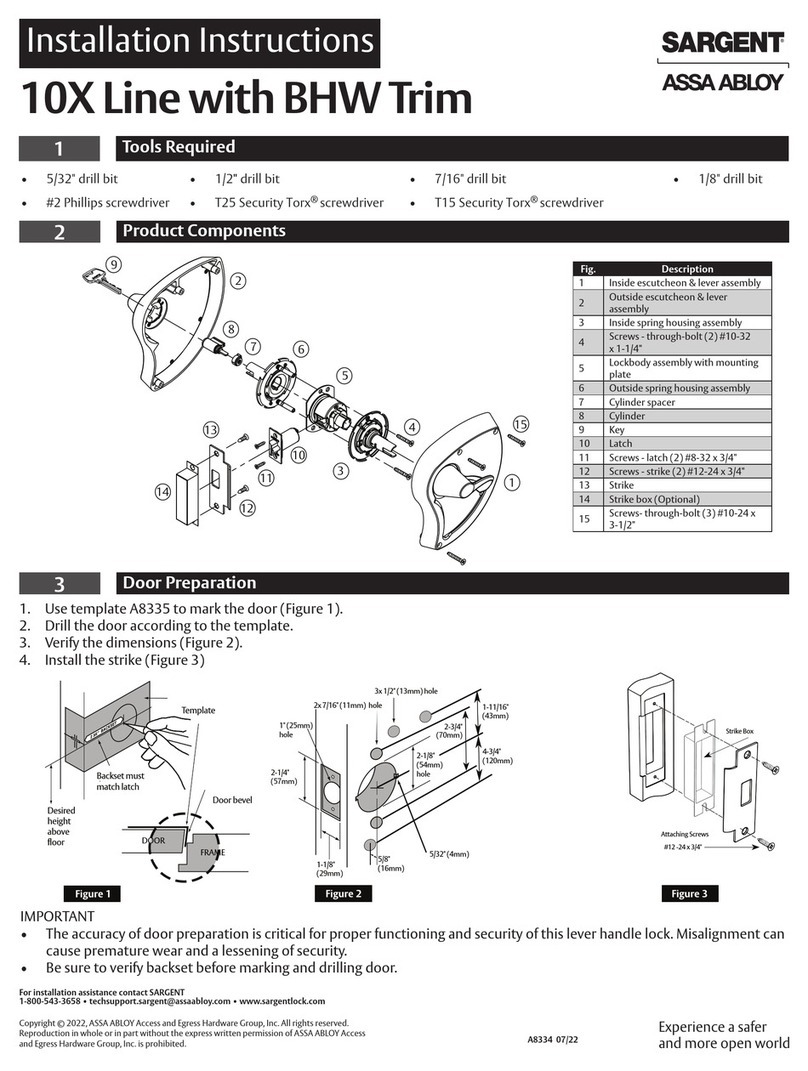
suit the door thickness.
• Position the spindle centrally through the latch bolt hub to suit
spindle (75mm).For door thicknesses of 35-50mm use
• For door thicknesses less than 35mm use the shorter
the longer spindle (85mm) or (100mm).
door handing as shown in the diagram above.
Viewed from
the outside
SPINDLE SHOULD ENGAGE
DOOR HUNG ON RIGHT
THE LATCH AS ABOVE
SPINDLE SHOULD ENGAGE
THE LATCH AS ABOVE
DOOR HUNG ON LEFT
Three spindles are provided. Select the spindle length to
7) Positioning the spindle
6) Handing the interior handle
assembly
The Interior Handle
Assembly is usually factory set
for left hand door handing.
(The handle will turn freely in
an anticlockwise direction only).
To change for a right hand door:
• Remove BLACK handling
screw from position A and
relocate it in position B.
Check that the inside handle now turns freely in a anti-clockwise
direction only.
Interior Handle
Assembly
HANDING
(POSITION A)
SCREWS
BLACK
(POSITION B)
direction and resists anticlockwise turning.
Check that the outer knob now turns freely in a clockwise
To change for a right hand door:
and resist clockwise turning).
in an anticlockwise direction
(The outer knob will turn freely
for left hand door handing.
Assembly is usually factory set
The Exterior Code Pad
5) Handing the code pad
PIN HERE
HAND DOOR
FOR LEFT
LOCATE
HANDING
HANDING
PIN
PIN
PLATE
COVER
SCREWS
HANDING
BLUE
• Replace handing pin cover
horizontally opposite.
replace it in the hole
• Remove the handing pin and
and handing pin cover plate.
• Remove the two BLUE screws
plate.
assembly
onto the door with the
spindle in position ensuring that the latchbolt support post
engages the hole in the latchbolt.
• Screw both sides together using the fixing bolts top and
door engaging the spindle in the handle hub.
• Locate the Interior Handle Assembly on the inside of the
functions correctly and moves easily.
• Before final tightening of the fixing bolts make sure the lock
is vertical. Test the mechanism to ensure that the lock
DO NOT overtighten the fixing screws - this may cause ġ
BEFORE CLOSING THE DOOR.
CHECK THAT THE CODE WORKS TO AVOID A LOCKOUT
distortion and lead to poor operation.
IMPORTANT :
bottom.
ġ
less than 48mm use
(36mm).
the shorter bolts
• For door thicknesses
• Hold the Exterior
Code Pad Assembly
Assemblies.
Exterior Code Pad
• Fit the neoprence
seals to both the
and Interior Handle
ġ
Select the fixing bolts to suit the door thickness.
8) Mounting the lock
LATCH STOP
STOPPER
LATCH
and slide the
is now working.
The hold open function
up the handle.
hand, turn the handle
latch stopper to keep
90 degrees to the left
If your door is left
10) Push button lock with hold open function
( Model P-DL02 only )
3
Fit latchbolt support post
Screw the Latchbolt Support Post in
the back of the Exterior Code
Pad Assembly. Hole A for left
hand hung door and Hole B for
right hand hung door.
A
B
9) Fitting the strike plate
the latchbolt onto the door frame.
• Close the door against the door frame
and transfer the centre of
• Position the strike plate on the door so
that it fits against the flat
of the latchbolt,with deadlatch
pluger depressed(Fig. 1).
• Close the door and mark the position
of the strike plate on the
door frame.
• Using the strike plate as a template,align it with the position marks
in the door frame and mark the inner and outer edges of the strike plate
on the door frame.
frame(Fig 2).
• Cut a 1mm deep rebate so that the strike plate fits flush with the door
• Drill and chisel out the latchbolt hole to accommodate the
strike box(Fig 3).
• Fit the strike plate and strike box using only one wood screw at first
to ensure that it is positioned accurately.
aperture freely and be held without excessive play.
• The latchbolt only and not the deadlatch plunger should enter the
and check lock set for smooth operation.
• When correctly positioned secure with the second wood screw
Fig. 3
"PLUNGER"
"LATCHBOLT"
Fig. 1 Fig. 2
7
C
Z
0
9
8
6
2 RED
square cut
square cut
Y
X
5
4
3
BLUE
1
correctly inserted.
procedure. Failure to do this
throughout code changing
held in the down position
button must be depressed and
Before Changing Codes The "C"
all be in line if codes are
a guideline red or blue should
code change instructions. As
correctly. Please refer to
codes are not re-inserted
similar damage will occur if
will damage the code module.
IMPORTANT:
4) Fit exterior code pad fixing lugs
Screw the fixing lugs into the back of the Exterior Code Pad
at the top and bottom.
Fig. 3
"PLUNGER"
"LATCHBOLT"
the latchbolt onto the jamb.
• Close the door against the door frame and transfer the centre of
9) Fitting the strike plate
Fig. 1
• Position the strike plate on the door so that it fits against the flat
of the latchbolt,with deadlatch pluger depressed(Fig. 1).
• Close the door and mark the position of the strike plate on the
door jamb.
• Using the strike plate as a template,align it with the position marks
in the jamb and mark the inner and outer edges of the strike plate
on the jamb.
jamb(Fig 2).
• Cut a 1mm deep rebate so that the strike plate fits flush with door
• Drill and chisel out the latchbolt hole to accommodate the latch
bolt strike box(Fig 3).
• Fit strike plate and strike box using only one wood screw at first
to ensure that it is positioned accurately.
aperture freely and be hold without excessive play.
• The latchbolt and not the deadlatch plunger should enter the
and check lock set for smooth operation.
• When correctly positioned secure with the second wood screw
Fig. 2
Changing the code number
clearing tumbler and
must not be removed.)
position. (this is the code
code tumbler in the "C"
tumblers plus 1 neutral
coloured "keyless" code
tumblers and 8 BLUE
coloured key active code
setting, there are 5 RED
3) From the factory code
module components.
spilling the small code
the code plate to avoid
flat surface when removing
to keep the lock body on a
Assembly. Take extra care
the back of the Exterior Code Pad
plate retaining screws from
2) Remove the 4 red code
CODE
PLATE
1) Remove the lock from the
door.
SCREWS
PLATE
CODE
RED
6) Establish and write down your new code and insert the
appropriate coloured tumbler next to the code numbers in
the module. DO NOT LEAVE ANY TUMBLER POSITION
EMPTY. With the spare tumblers provided in the screw pack
you can reduce or increase your code to 4 or 6 digits.
safe place with the instructions and code.
10) Reinstall the lock and place the spare colour code tumblers in a
7) Replace the code plate and secure with the 4 red retaining
8) Check the code by pressing the "C" button followed by the
9) The knob should turn freely in both directions if not return
to step 4 and confirm that the instructions have been fully
followed.
code number.
screws.
code module.
the code tumblers before
re-inserting them into the
5) Note the different shapes of
using the tweezer supplied.
one or more code tumblers
"C" button held down, remove
button code tumbler. With the
Never attempt to remove the "C"
4) Push and hold the "C" button.
SQUARE CUT MUST ALWAYS FACE THE OUTSIDE OF THE
RED and BLUE code tumblers have the square cut low and
high respectively. WHEN REPLACING CODE TUMBLERS THE
LOCK BODY.
BLUE
KEYLESS
TUMBLER
BLUE
square
cut
RED
RED KEY
cut
square
TUMBLER
push button
square cut
outside outside
number
7
C
Z
0
9
8
6
2RED
square cut
square cut
Y
X
5
4
3
BLUE
1
procedure. Failure to do this
throughout code changing
held in the down position
button must be depressed and
Before changing codes the "C"
code change instructions.
correctly. Please refer to
codes are not re-inserted Similar damage will occur if
will damage the code module.
IMPORTANT:
