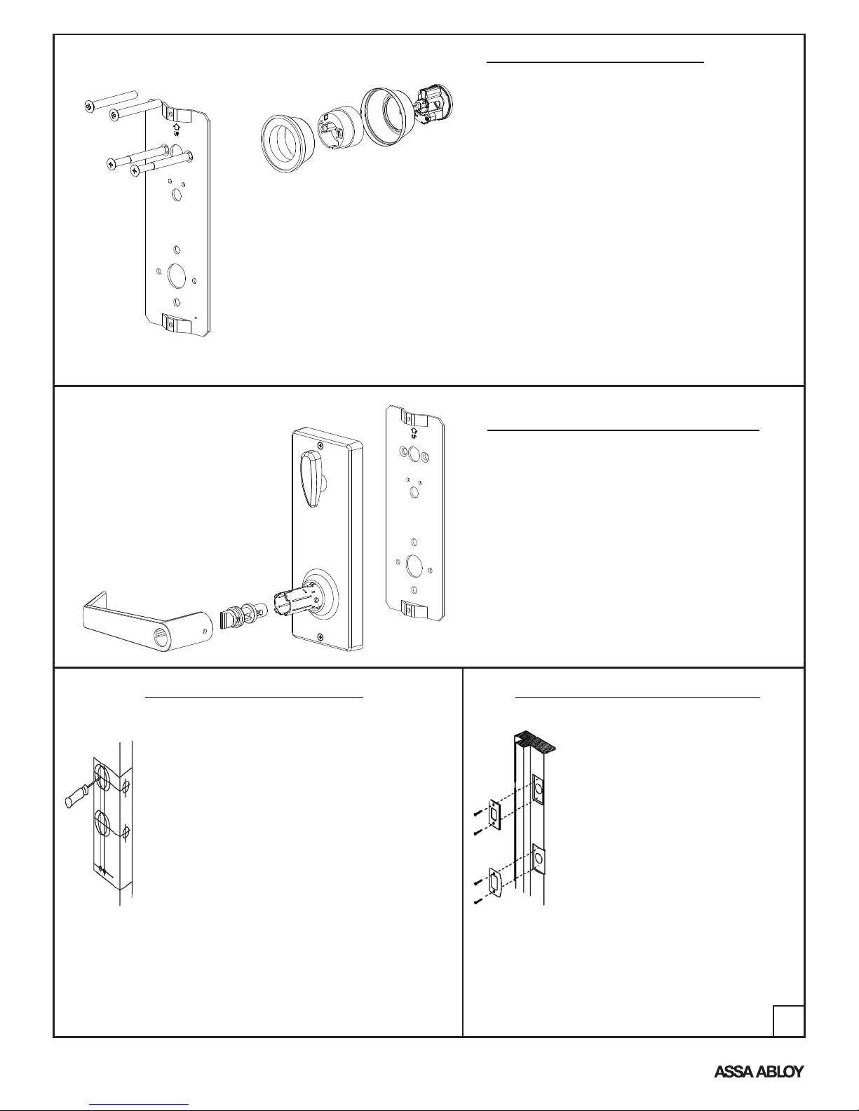
INTERIOR MECHANISM HOUSING
Reinstall the interior mechanism housing on the
installation plate with the two self-thread screws
saved before. Once this operation is done,
the square spindle for the interior
mechanism housing is inside the hub of the
lower latch and operates the latch. Note that the
thumbturn must be in the vertical position then
slide the lever over the bottom tube and proceed
same as with the exterior assembly.
make
sure
1. To prepare door frame for strike
plates, locate the strike plates'
center position. Marked on the
stage 4 for “new door preparation”.
2. Trace outlines of strike plates.
Carefully chisel away outlined
areas until plates fit flush.
3. With a 1" (25mm) drill bit, drill a 1"
(25mm) deep hole at the upper
strike plate to accept the bolt.
4. With a 1"(25mm) drill bit, drill a
1/2"(13mm) deep hole at the lower
strike plate to accept the latch bolt.
5. Drill pilot holes for the plate
mounting screws.
6. Secure the strike plates with (2)
3/4" screws.
NEW DOOR PREPARATION
1. Fold template as marked and place on door. If
corner of door is beveled, place template on
widest side of door.
2. Mark centers for all holes. Drill 1/8" (3mm) pilot
holes at centers. Drill completely through door
thickness.
3. Bore 2-1/8" (54mm) hole halfway through door.
Finish bore from other side to prevent
splintering.
4. To mark strike location, close the door and push
locator pin through both guide holes marking
the strike plates center position.
5. Bore 2 holes 1" (25mm) through the door edge.
6. For handleset installation only: Bore 5/16" hole
to receive bottom portion of handleset.
7. Insert the latch and then trace outlines of
latchplates. Carefully chisel away outlined areas
until plates fit flush. Drill pilot holes for
latchplates mounting screws. 3
An ASSA ABLOY Group brand
P/N 80-9510-0056-010 Rev B
DEADBOLT INSTALLATION
Unscrew the top and bottom screws from the
interior mechanism housing and remove the
installation plate. Save these screws to reinstall
housing on the installation plate.
The exterior deadbolt assembly has a blade
(tailpiece) attached to the rear of the cylinder.
This tailpiece passes through the latch and
engages the interior assembly. Insert the key in
the cylinder so that the flat edge of the key is
down and slide the tailpiece through the
horizontal slot in the latch. Insert the deadbolt
connecting screws through the installation plate
and connect the plate with the exterior deadbolt
housing. Slightly tighten these two screws.
Deadbolt screws are 1/4" x 2-1/2" for 2" to 1-1/2"
thickness doors. Use 1/4" x 2-1/16" screws also
included for 1-3/8" thickness doors. DO NOT
INSTALL WITH THE DEADBOLT EXTENDED.
STRIKE PLATE INSTALLATION