Q50257 - Yale Quattro Sliding 3 Point Lock Kit
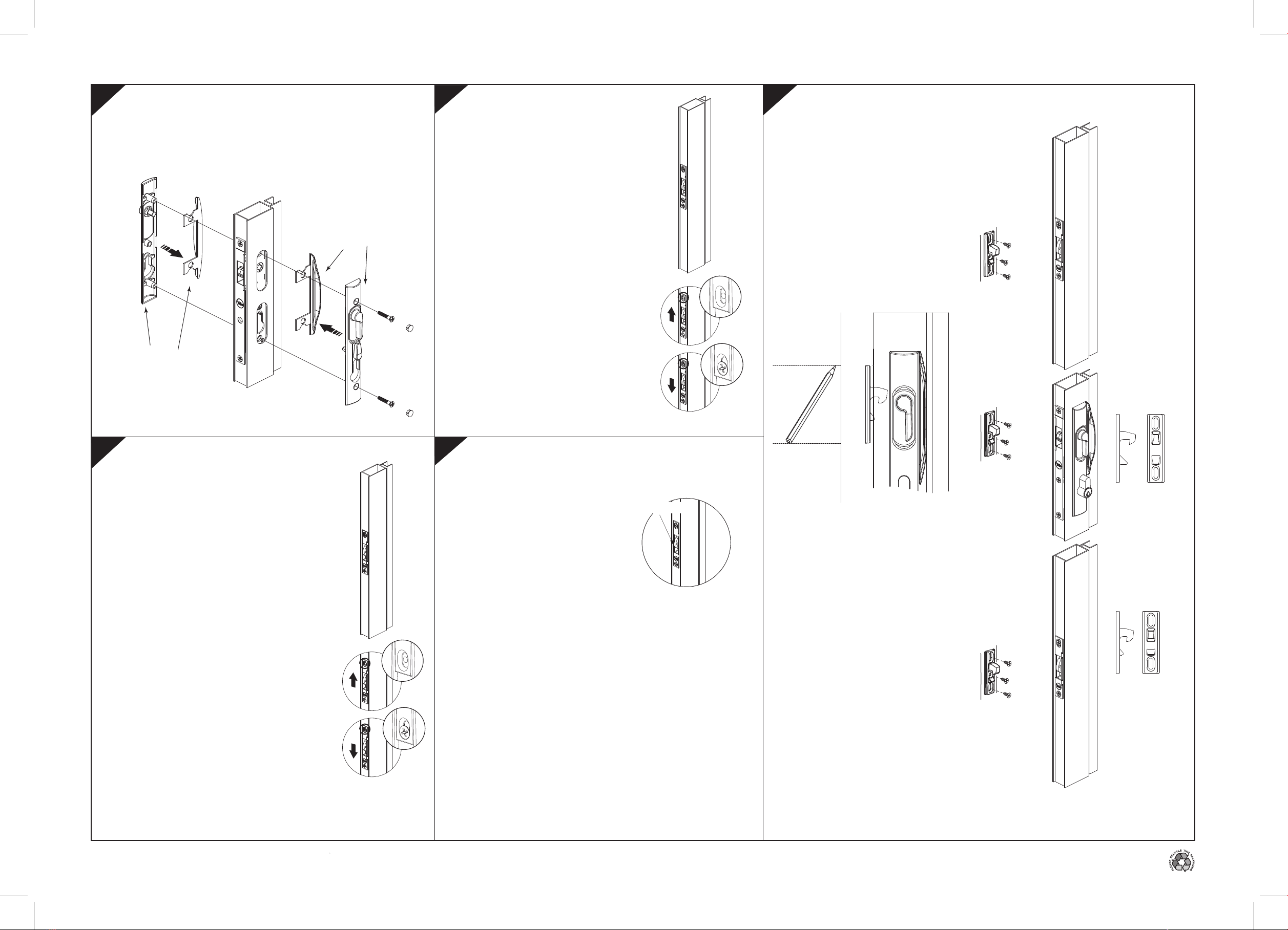
Step A Ensure the lock is in the "Secure"
(Deadlock) position. Gently push the
bottom lock until it stops.
Drill a Ø3mm hole in the centre
of the slot, and loosely fit the first
fixing screw.
Step B Push the lock towards the
bottom of the door, tighten the
first screw.
Check the beak position as per
Step 5. Unlock and lock the
main lock to check operation.
Ensure the lock is in the "Secure"
(Deadlock) position, drill and
fasten the second
screw.
Installation of Bottom Auxilary Lock
Installation of Top Auxilary Lock
Step A Ensure the lock is in
the "Secure" (Deadlock) position.
Gently push the top lock until it stops.
Drill a Ø3mm hole in the centre of
the slot, and loosely fit the first
fixing screw.
Step B Push the lock towards the
top of the door, tighten the
first screw.
Check the beak position as per
Step 5. Unlock and lock
the main lock to check operation.
Ensure the lock is in
the "Secure"(Deadlock) position, drill
and fasten the second screw.
For correct function ,
the beak should remain
secure when pressure is
applied in deadlocked
state.
To check correct function,
deadlock the door and
apply downwards pressure
with a screw driver, in position
shown. If the beak releases, the lock is
now out of sync. Re-sychronise the lock and
adjust the lock slightly downwards. Deadlock,
and repeat test until the beak is secure.
2
Checking of Top and Bottom Auxilary Locks
46
For the main lock drill two
Ø3mm holes and fit to door
jamb where marked using
12mm countersunk screws.
Adjust striker to correct
position and then tighten
screws. For timber
jambs, use longer
10g screws provided.
Repeat the process
with the top and bottom
strikers using the 8g screws
provided.
Part of ASSA ABLOY
Use larger
strikers on Top
and Bottom locks
Use smaller
striker on the
Main lock
Mounting the Striker
With the strikers inserted in the
main lock body, and the top and
bottom locks, either mark the
position on the outside of the
jamb or remove the backing from
the tape and allow the strikers to
stick to the frame. Remove
strikers from locks.
35
After ascertaining the handing configuration required, simply press
the desired handle plates together and install the operating levers
and external restrictor plate as required. Then secure the furniture
plates to the door section using the two 25mm screws &
plugs supplied.
For further installation detail, reference the
standard Yale Quattro Sliding single point lock Instructions
Press together the External
Escutcheon Plate and the
Pull Handle, before
securing to the door
Press together the Internal
Escutcheon Plate and the
Pull Handle, before
securing to the door
Press here
with screwdriver
A
B
A
B


