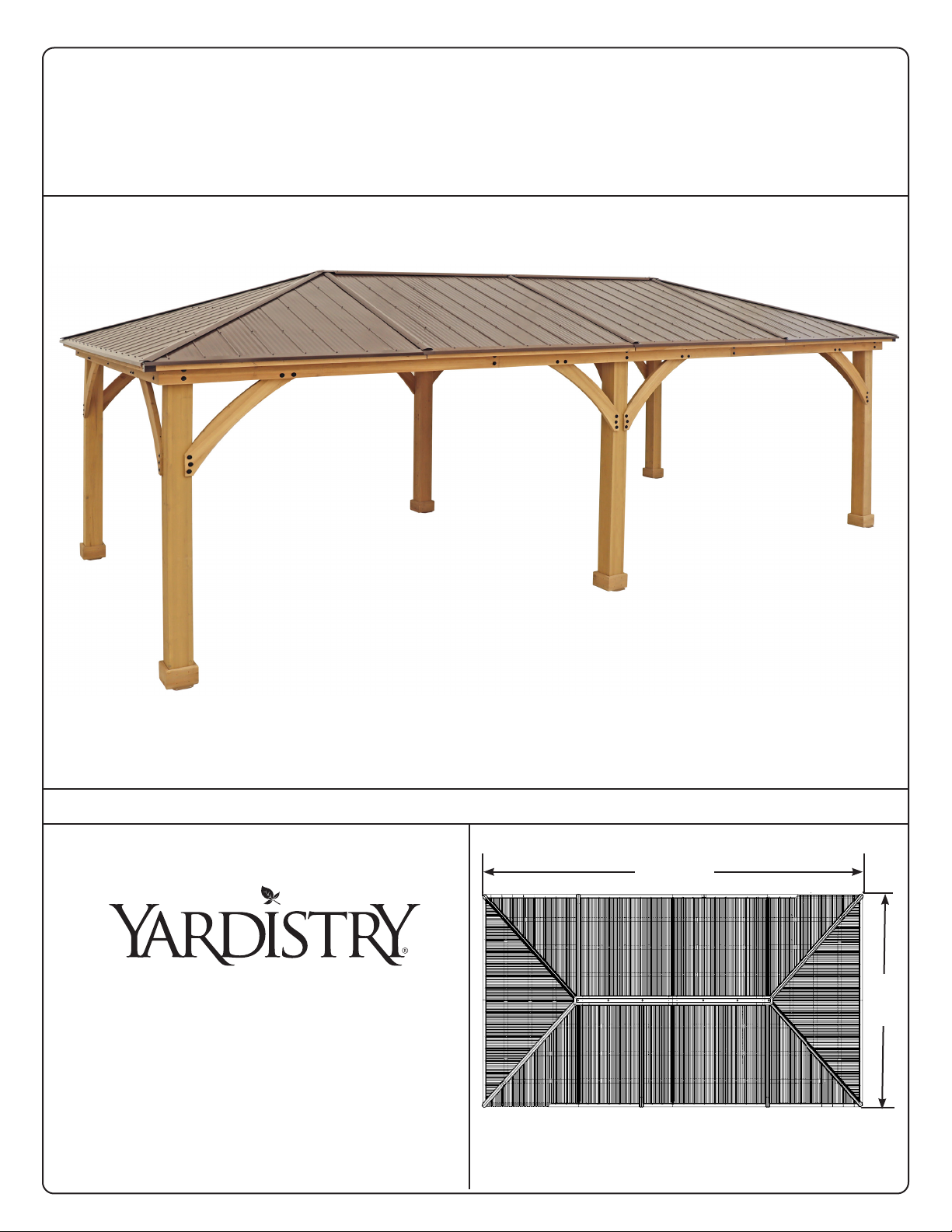
Yardistry MERIDIAN YM11937 User manual
Other Yardistry Outdoor Furnishing manuals

Yardistry
Yardistry YM12837 User manual

Yardistry
Yardistry YM12784 User manual

Yardistry
Yardistry CS002 Series User manual

Yardistry
Yardistry SENECA PRIVACY ARBOR SPA8 YM14126 User manual

Yardistry
Yardistry 12' x 12' MERIDIAN GAZEBO YM11769 User manual

Yardistry
Yardistry AVERY User guide

Yardistry
Yardistry YM11915 User manual

Yardistry
Yardistry YM12904 User manual

Yardistry
Yardistry 1902316 User manual

Yardistry
Yardistry YM12705Z User manual

Yardistry
Yardistry YM12810 User manual

Yardistry
Yardistry YM12631X User manual

Yardistry
Yardistry YM12952 User manual

Yardistry
Yardistry YM11640 User manual

Yardistry
Yardistry MERIDIAN OCTAGON YM11924 User manual

Yardistry
Yardistry YM12941Z User manual

Yardistry
Yardistry CS016 Series User manual

Yardistry
Yardistry YM11629 User manual

Yardistry
Yardistry YM11627 User manual

Yardistry
Yardistry Structures CS008 Series User manual


Popular Outdoor Furnishing manuals by other brands

felton industries
felton industries FELEPG5T6 Assembly instruction

Dreamo
Dreamo OTF-503S quick start guide

Garden Furniture Direct
Garden Furniture Direct Borrowdale Assembly instructions

Rowlinson
Rowlinson Clarendon Assembly instructions

Garden Treasures
Garden Treasures 8201268 Assembly instructions

Safavieh Outdoor
Safavieh Outdoor Marson PAT7062 quick start guide

SSC-LUXon
SSC-LUXon 990070716 Assembly & operating instructions

supremo LEISURE
supremo LEISURE 2-Seat Stool 110*40cm Assembly instruction

Hatteras Hammocks
Hatteras Hammocks DCA1-K-HH instructions

Lemeks
Lemeks Palmako PA120-5959 Assembly, installation and maintenance manual

OLT
OLT 24 Assembly manual

forest-style
forest-style HACIENDA 2354 Building instructions

Courtyard Creations
Courtyard Creations RUS0188-WM Assembly instructions

kingsley-bate
kingsley-bate MC-55 Assembly instructions

Weltevree
Weltevree Carrier product manual

Grange Fencing
Grange Fencing Elite Arch Assembly instructions

Grosfillex
Grosfillex AUVENT YR14 Assembly instructions

X-METAL
X-METAL EAGLE 33511 Assembly instructions