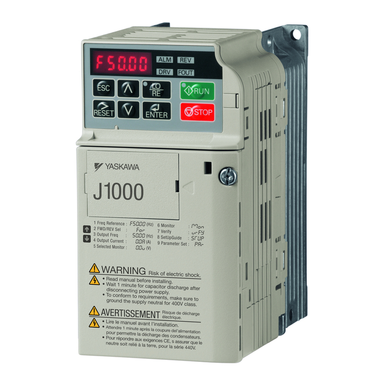
manuals.online logo
Brands
  1. Home
  2. •
  3. Brands
  4. •
  5. YASKAWA
  6. •
  7. Controllers
  8. •
  9. YASKAWA PROFINET V1000 User manual

YASKAWA PROFINET V1000 User manual

MANUAL NO. TM.V1000SW.029
Traverse Application
YASKAWA AC Drive - V1000
Custom Software Supplement
Software Number: VSV91004□
Drive Models: VU□A□□□□□□□
To properly use the product, read this manual thoroughly and retain
for easy reference, inspection, and maintenance. Ensure the end user
receives this manual.
YASKAWA AMERICA, INC. TM.V1000SW.029 Traverse Application V1000 Custom Software Supplement 3
Table of Contents
1 PREFACE AND SAFETY . . . . . . . . . . . . . . . . . . . . . . . . . . . . 5
2 PRODUCT OVERVIEW . . . . . . . . . . . . . . . . . . . . . . . . . . . . . . 8
3 NEW AND MODIFIED SOFTWARE FUNCTIONS . . . . . . . . . 9
Refer to the V1000 Technical Manual for content not described in this document.
4YASKAWA AMERICA, INC. TM.V1000SW.029 Traverse Application V1000 Custom Software Supplement
This Page Intentionally Blank
YASKAWA AMERICA, INC. TM.V1000SW.029 Traverse Application V1000 Custom Software Supplement 5
1 Preface and Safety
Yaskawa manufactures products used as components in a wide variety of industrial systems
and equipment. The selection and application of Yaskawa products remain the responsibility
of the equipment manufacturer or end user. Yaskawa accepts no responsibility for the way its
products are incorporated into the final system design. Under no circumstances should any
Yaskawa product be incorporated into any product or design as the exclusive or sole safety
control. Without exception, all controls should be designed to detect faults dynamically and
fail safely under all circumstances. All systems or equipment designed to incorporate a
product manufactured by Yaskawa must be supplied to the end user with appropriate
warnings and instructions as to the safe use and operation of that part. Any warnings
provided by Yaskawa must be promptly provided to the end user. Yaskawa offers an express
warranty only as to the quality of its products in conforming to standards and specifications
published in the Yaskawa manual. NO OTHER WARRANTY, EXPRESS OR IMPLIED, IS
OFFERED. Yaskawa assumes no liability for any personal injury, property damage, losses,
or claims arising from misapplication of its products.
1 Preface and Safety
6YASKAWA AMERICA, INC. TM.V1000SW.029 Traverse Application V1000 Custom Software Supplement
◆Applicable Documentation
The following manuals are available for the V1000 Drive:
◆Supplemental Safety Information
Read and understand this manual and the V1000 Quick Start Guide before installing,
operating, or servicing the drive. The drive must be installed according to the V1000 Quick
Start Guide and local codes. Observe all cautions and warnings in this document and the
standard drive technical manuals.
Refer to the V1000 Quick Start Guide and the V1000 Technical Manual for safety
information and installation and start-up instructions.
This supplement describes the effects of the Traverse Application software on the standard
drive parameters and functions.
• Custom software is provided to add functionality to a standard AC drive to enhance or
enable use in a specific application.
• The software is loaded to the flash ROM area of the control board, and replaces the
standard drive software.
Custom Software Supplement
Yaskawa AC Drive - Traverse Application V1000 Custom Software Supplement
Manual No: TM.V1000SW.029
Read this supplement first. This supplement is an addendum to the V1000 Quick
Start Guide and Technical Manual. It lists the effects of this custom software on the
parameters in the drive and function descriptions in the manual.
To obtain a PDF of this supplement, access this site: U.S: http://www.yaskawa.com
Yaskawa Drive
Yaskawa AC Drive -
V1000 Quick Start
Guide
To obtain instruction manuals for Yaskawa products access
these sites:
U.S.: http://www.yaskawa.com
Other areas: contact a Yaskawa representative.
For questions, contact the local Yaskawa sales office or the
nearest Yaskawa representative.
Yaskawa AC Drive -
V1000 Technical
Manual
SUPPLEMENT
1 Preface and Safety
YASKAWA AMERICA, INC. TM.V1000SW.029 Traverse Application V1000 Custom Software Supplement 7
◆Obtaining Support
The part number shown on the drive nameplate must be provided when seeking support for a
drive with custom software. The software is flashed to the control board memory and the
operation of parameters, functions, and monitors are different than the standard drive
software, as described herein.
Refer to Yaskawa office locations listed on the back cover of this supplement.
8 YASKAWA AMERICA, INC. TM.V1000SW.029 Traverse Application V1000 Custom Software Supplement
2 Product Overview
2 Product Overview
◆About This Product
This custom software is designed specifically for use in Traverse applications.
◆Applicable Models
This custom Traverse application software is available for the V1000 drive models listed in
Table 1.
Table 1 Applicable Models
Voltage Class Models Software Version <1>
<1> See “PRG” on the drive nameplate for the software version number.
200 V Single-Phase VUBA0001F to BA0018F VSV91004
200 V Three-Phase VU2A0001F to 2A0069F VSV91004
400 V Three-Phase VU4A0001F to 4A0038F VSV91004
YASKAWA AMERICA, INC. TM.V1000SW.029 Traverse Application V1000 Custom Software Supplement 9
3 New and Modified Software Functions
◆Traverse Anti-Phase
■Overview
The Traverse Anti-Phase function controls the traverse arm of a winder in textile industry
applications. This function generates a dithered disturbed waveform that is used as
frequency reference for the traverse arm drive and also provides an anti-phase signal for
output to a spindle slave drive for better winding.
■Basic Concept
When the drive reaches the set frequency reference, the output frequency waveform is
modulated in a triangular pattern to randomize fiber overlap on the spindle and produce a
tighter wrap and higher quality wound package.
P1- parameters set the attributes of the disturbed waveform, a triangle wave with
instantaneous jumps at the peak and trough. This triangle wave rides on top of the base
frequency reference for the traverse drive.
The signal output to control the slave spindle drive can be set to one of three monitors:
U7-02, Absolute Slave Frequency, U7-03, Ripple Slave Frequency, or U7-04, Slave Base
Frequency. U7-02 and U7-03 have an anti-phase component and output a disturbed
waveform that is the inverse (anti-phase) of the master disturbed waveform. The anti-phase
waveform ignores the jump portion of the master traverse disturbed waveform.
■Limitations
• This software substitutes English text for Japanese when Japanese is selected (A1-00 = 1).
Chinese language support (A1-00 = 7) has been removed.
• Parameter L4-02, Speed Agree Detection Width, should be set to a small, non-zero value
to avoid unintended jumps in the disturbed waveforms.
• When P1-04 and P1-05 are set to short slope times, set L4-02 to a value greater than
0.5 Hz to prevent inconsistent traverse operation.
• Step changes in frequency reference result in unintended jumps in the disturbed
waveforms. Disable the Traverse function using H1- = 80h to prevent damage to the
motor or connected equipment before making large changes in the frequency reference.
• The Traverse waveform can be configured to be smaller than the input resolution of the
V1000 slave drive frequency reference. Ensure that Master Frequency Reference × P1-02
is significantly larger than (Slave Maximum Output Frequency/1000) for proper control
of the slave drive.
3 New and Modified Software Functions
10 YASKAWA AMERICA, INC. TM.V1000SW.029 Traverse Application V1000 Custom Software Supplement
■Related Parameters and Functions
Table 2 Modified Parameter
Table 3 Additional Parameters
Note: All additional P1 parameters can be changed during run.
No.
MEMOBUS/
Modbus
Address
Name
Digital Operator
Display
Description Range Default
Value
A1-00 0100h Language Selection
Select Language
0: English
1: Japanese
2: German
3: French
4: Italian
5: Spanish
6: Portuguese
0 to 6 0
No.
MEMOBUS/
Modbus
Address
Name
Digital Operator
Display
Description Range Default
Value
P1-01 0600h
Disturbed P1-05
Waveform Selection
Disturb WF Sel
Enables and disables the traverse disturbed
waveform function.
0: Disabled
1: Enabled
0, 1 0
P1-02 0601h
Disturbed Waveform
Amplitude
Disturb WF Amp
Sets the amplitude of the disturbed waveform
as a percentage of the commanded frequency
reference.
Note: Setting this parameter to 0 disables the
Traverse function.
0.0 to 20.0% 0.0
P1-03 0602h
Disturbed Waveform
Jump
Disturb WF Jmp
Adds a notch or “jump” below the peak
amplitude of the disturbed waveform when set
to a non-zero value. Set as a percentage of
P1-02, Disturbed Waveform Amplitude.
0.0 to 50.0% 0.0
P1-04 0603h Negative Slope Time
Neg Slope Time
Sets the time for the disturbed waveform to
decelerate from the maximum value
(reference + P1 02) to the minimum value
(reference - P1-02).
Note: Setting this parameter to 0.0 disables the
Traverse function.
0.0 to 120.0 s 0.0
P1-05 0604h Positive Slope Time
Pos Slope Time
Sets the time for the disturbed waveform to
accelerate from the minimum value
(reference - P1 02) to the maximum value
(reference + P1-02).
Note: Setting this parameter to 0.0 disables the
Traverse function.
0.0 to 120.0 s 0.0
P1-06 0605h Slave Scan Offset
Slv Scan Offset
Monitors shift (U7-02, U7-03, and U7-04) in
ms to compensate for systematic delays. -24 to 24 ms 0
3 New and Modified Software Functions
YASKAWA AMERICA, INC. TM.V1000SW.029 Traverse Application V1000 Custom Software Supplement 11
Table 4 Additional Parameter Function Group
Table 5 Additional Parameter Function Number
Table 6 Additional Monitor Function Number
Table 7 Additional Monitors
Table 8 Additional Multi-Function Input Settings (H1-)
Function Group Group Name
Digital Operator Display
PTraverse Group
Traverse
Function No. Description
P1 Disturbed Waveform Adjustment
Disturb WF Adj
Function No. Description
U7 Traverse Monitors
Traverse
No.
MEMOBUS/
Modbus
Address
Name
Digital Operator
Display
Description
Analog
Output
Scaling
Unit
U7-02 0661h
Absolute Slave
Frequency
Slv Abs Freq
Base frequency reference summed with the anti-
phase dither.
10 V: Max
Frequency
(E1-04)
0.01 Hz
U7-03 0662h
Ripple Slave
Frequency
Slv Ripple Freq
Anti-phase dither summed with 50% of E1-04.
During reverse operation, displays a negative
frequency reference. The analog output will
remain positive for both run directions.
10 V: Max
Frequency
(E1-04)
0.01 Hz
U7-04 0663h
Base Slave
Frequency
Slv Base Freq
Base frequency reference (before disturbed
waveform is applied).
10 V: Max
Frequency
(E1-04)
0.01 Hz
No. Description
80h
Disturbed WF Off
Open: Disturbed waveform enabled
Closed: Disturbed waveform disabled
3 New and Modified Software Functions
12 YASKAWA AMERICA, INC. TM.V1000SW.029 Traverse Application V1000 Custom Software Supplement
Table 9 Additional Multi-Function Output Settings (H2-)
■Function Description
The disturbed waveform begins when the drive reaches Speed Agree (bandwidth adjustable
by parameter L4-02). The disturbed waveform rides on top of the base frequency reference
for the traverse drive.
Adjusting the frequency reference of the master drive while the disturbed waveform is active
produces an output that is the frequency reference waveform summed with the disturbed
waveform.
The dithering is a triangle waveform with amplitude and slope set by P1-02, P1-04, and
P1-05. The traverse drive also has a jump in the dithering waveform set by parameter P1-03.
The anti-phase output signal is the disturbed portion of the traverse frequency reference with
the signal inverted. Only the triangle portion of the disturbed waveform is used for the anti-
phase output; the jump is ignored.
The Traverse application software has three monitors: U7-04, Base Slave Frequency, outputs
the frequency reference of the drive before the disturbed waveform is applied; U7-03, Ripple
Slave Frequency, outputs the anti-phase of the disturbed portion of the waveform summed
with 50% of Maximum Output Frequency parameter E1-04; and U7-02, Absolute Slave
Frequency, outputs the anti-phase of the disturbed portion of the waveform summed with
U7-04.
All three monitors can be set to analog outputs, however U7-02 or U7-03 would generally be
used as an analog output going to the slave (spindle) for the frequency reference. U7-02
provides the slave with a complete reference signal. U7-03 is used as a dither reference if the
slave should use its own base frequency reference (as shown in the Application Example on
page 13).
To compensate for system delays, U7-02, U7-03, and U7-04 can be set to lead or lag the
traverse control output by 0 to 12 scans (0 to 24 ms) using parameter P1-06.
No. Description
40h
Disturb UP Sts
Open: The disturbed waveform frequency is decreasing
Closed: The disturbed waveform frequency is increasing
41h
During Disturb
Open: Disturbed waveform disabled
Closed: Disturbed waveform being generated
3 New and Modified Software Functions
YASKAWA AMERICA, INC. TM.V1000SW.029 Traverse Application V1000 Custom Software Supplement 13
■Application Example
In the application shown in Figure 1, the slave drive is configured to run at its own
frequency reference provided at terminal A1. The Anti-Phase Slave Ripple Frequency
component is connected to analog input terminal A2 of the slave drive, with terminal bias
and offset set so that the Slave Ripple Frequency component alone will be a bipolar signal
oscillating around 0 Hz. This signal, summed with the Slave Frequency Reference at
terminal A1, sets the overall frequency reference for the drive.
Figure 1
Figure 1 Software and Hardware Configuration for V1000 Traverse
Master Parameter Changes:
• P1-01 = 1: Enable Traverse functionality.
• P1-02 to P1-05 = application requirements: Define the characteristics of the disturbed
frequency.
• P1-06 = application requirement: Define scan offset to account for system delays.
• H2-01 = 41h: Provide during disturb status output to slave.
• H4-01 = 703: Provide disturbed frequency ripple to slave.
Slave Parameter Changes
• C1-03 = 0.0 sec: Set acceleration time 2 to 0.0 sec.
• C1-04 = 0.0 sec: Set deceleration time 2 to 0.0 sec.
• H1-07 = 7: Switch between accel/decel time 1/2 based on During Disturb output.
• DIP Switch S1 = V: Enable voltage input to A2.
• H3-09 = 1: Set A2 to a 0 to 10V bipolar input.
• H3-11 = 50.0%: Set the gain to equate a 10 V signal to 30 Hz (50% of E1-04).
• H3-12 = -50.0%: Set the bias to equate a 0 V signal to -30 Hz (-50% of E1-04).
H2-01 = 41
H4-01 = 703
AM
AC
MA
MC
V1000 (Master)
Traverse Software
+
Slave
Frequency
Reference
-
A2
AC
S7
SC
H1-07 = 7
H3-09 = 1
H3-11 = 50
H3-12 = -50
A1
V1000 (Slave)
Standard Software
DIP Switch S1
VI
3 New and Modified Software Functions
14 YASKAWA AMERICA, INC. TM.V1000SW.029 Traverse Application V1000 Custom Software Supplement
Figure 2
Figure 2 Master and Slave Output Diagram: Standard Operation
■Implementation
Situation 1: Standard Operation
When programmed with the settings shown in Table 10, the Traverse software produces
output waveforms similar to the ones in Figure 2. Using these settings and a reference
frequency of 45 Hz, the master drive operates based on the triangle waveform with 9 Hz
peak amplitude. Because the waveform is centered on the 45 Hz reference frequency, the
master waveform oscillates between 36 and 54 Hz while in Traverse mode.
Table 10 Sample Operating Parameters
Parameter Name Setting
P1-01 Disturbed P1-05 Waveform Selection 1
P1-02 Disturbed Waveform Amplitude 20.0%
P1-03 Disturbed Waveform Jump 50.0%
P1-04 Negative Slope Time 5.0 s
P1-05 Positive Slope Time 4.0 s
Run
command
Frequency
reference
0
U7-02
Slave Absolute
Frequency
U7-02
Slave Base Frequency
U7-03
Slave Ripple
Frequency
E1-04 x 50% (Hz)
Speed Agree
Disturb UP Status
multi-function output
During Disturbed
multi-function output
P1-02 x
Freq. Ref.
P1-02 x
Freq. Ref.
P1-02 x
Freq. Ref.
P1-02 x
Freq. Ref.
P1-02 x
Freq. Ref.
P1-02 x Freq. Ref. x P1-03
2 - P1-03
P1-02 x Freq. Ref. x P1-03
2 - P1-03
P1-02 x
Freq. Ref.
P1-04 P1-05
3 New and Modified Software Functions
YASKAWA AMERICA, INC. TM.V1000SW.029 Traverse Application V1000 Custom Software Supplement 15
U7-02, Slave Absolute Frequency, (available as an output to the slave by setting parameter
H4-01 to 702), has the same amplitude of 9 Hz (calculated by P1-02 × Reference
Frequency). U7-02 is anti-phase to the master waveform and is centered around U7-04, the
Slave Base Frequency. Since the Slave Base Frequency is 45 Hz, U7-02 varies from 36 to
54 Hz while in Traverse mode. Before entering Traverse mode, the Slave Absolute
Frequency rests at 48 Hz as represented by the equation in Figure 2.
U7-03, Slave Ripple Frequency, is similar to U7-02, except that this anti-phase dither is
centered around 50% of the drive Maximum Output Frequency. With E1-04 set to 60.0 Hz,
U7-03 is centered around 30 Hz, and varies from 21 to 39 Hz during operation. Before
entering Traverse mode, the Slave Ripple Frequency rests at 33 Hz, as represented by the
equation in Figure 2.
Situation 2: Traverse Operation Exceeds Maximum Output Frequency
Using the settings in Table 10 and a reference frequency of 52 Hz, the Traverse software
produces output waveforms similar to those in Figure 3. With an amplitude of 10.4 Hz, the
traverse software produces a triangle output that varies from 41.6 to 62.4 Hz. Setting drive
parameter E1-04 to 60.0 Hz, caps the triangle waveform when the traverse frequency
exceeds the Maximum Output Frequency of 60 Hz.
Figure 3
Figure 3 Traverse Mode Operation Outside of Maximum Output Frequency E1-04/E3-04
P1-06 Slave Scan Offset 0 ms
Parameter Name Setting
Run
command
E1-04
Maximum
Frequency
Frequency
reference
0
E1-04
U7-02
Slave Absolute
Frequency
U7-02
Slave Base Frequency
U7-03
Slave Ripple
Frequency
E1-04 x 50% (Hz)
Speed Agree
Disturb UP Status
multi-function output
During Disturbed
multi-function output
3 New and Modified Software Functions
16 YASKAWA AMERICA, INC. TM.V1000SW.029 Traverse Application V1000 Custom Software Supplement
Situation 3: Changing Reference Frequency
Using the settings in Table 10 and a reference frequency that changes from 20 Hz to 30 Hz,
the Traverse software produces output waveforms similar to those in Figure 4. Using a
20 Hz frequency reference, the master drive oscillates between 16 and 24 Hz. When the
reference frequency increases to 30 Hz, the drive exits Traverse mode and accelerates using
the default acceleration time set in C1-01. When the drive reaches the new frequency
reference, it re-enters Traverse mode and the master drive oscillates between 24 and 36 Hz.
Initially, U7-02, Slave Absolute Frequency, rests at 21.33 Hz. When the drive enters
Traverse mode, U7-02 oscillates between 16 and 24 Hz. When the reference frequency
changes, the drive exits Traverse mode and the Slave Absolute Frequency rises to 32 Hz
until the drive re-enters Traverse mode. Once resuming traverse mode, the new waveform
oscillates between 24 and 36 Hz.
U7-03, Slave Ripple Frequency, operates similar to U7-02, except that its waveform is
centered around [50% × E1-04], which does not change with the reference frequency.
Step changes in frequency reference result in unintended jumps in the disturbed waveforms.
Disable the Traverse function using H1- = 80h to prevent damage to the motor or
connected equipment before making large changes in the frequency reference.
3 New and Modified Software Functions
YASKAWA AMERICA, INC. TM.V1000SW.029 Traverse Application V1000 Custom Software Supplement 17
Figure 4
Figure 4 Traverse Mode Operation with Changing Frequency Reference
Run
command
Frequency
reference
P1-02 x
Freq Ref
P1-02 x
Freq Ref
P1-02 x Freq Ref x P1-03
P1-02 x Freq Ref x
P1-03
Disturb UP Status
multi-function output
During Disturbed
multi-function output
Speed Agree
0
P1-04 P1-05
E1-04 x 50% (Hz)
U7-03
Slave Ripple Frequency
P1-02 x
Freq Ref
P1-02 x
Freq Ref
P1-02 x
Freq Ref*
P1-02 x Freq Ref* x P1-03
P1-02 x
Freq Ref*
P1-04 P1-05
P1-02 x Freq Ref* x P1-03
P1-02 x
Freq Ref*
P1-02 x
Freq Ref*
Accel Time 1
(C1-01)
Accel Time 1
(C1-01)
P1-02 x Freq Ref x P1-03
2 - P1-03
P1-02 x
Freq Ref
P1-02 x
Freq Ref
P1-02 x
Freq Ref*
P1-02 x
Freq Ref*
P1-02 x Freq Ref* x P1-03
2 - P1-03
P1-02 x Freq Ref x P1-03
2 - P1-03
U7-04
Slave Base Frequency
U7-02
Slave Absolute
Frequency
80h
Disturbed
WF Off
P1-02 x Freq Ref x P1-03
2 - P1-03
P1-02 x Freq Ref* x P1-03
2 - P1-03
P1-02 x Freq Ref x P1-03
2 - P1-03
3 New and Modified Software Functions
18 YASKAWA AMERICA, INC. TM.V1000SW.029 Traverse Application V1000 Custom Software Supplement
◆Revision History
The revision dates and the numbers of the revised manuals appear on the bottom of the back
cover.
Date of
Publication
Revision
Number Software Number Revised Content
March 2013 - VSV91004First release
MANUAL NO.ޓTM.V1000SW.029
Published in U.S.A. March 2013 13-3
Date of
publication
Date of original
publication
Revision number
1
Traverse Application
YASKAWA AC Drive - V1000
Custom Software Supplement
YASKAWA AMERICA, INC.
2121 Norman Drive South, Waukegan, IL 60085, U.S.A.
Phone: (800) YASKAWA (927-5292) or 1-847-887-7000 Fax: 1-847-887-7310
http://www.yaskawa.com
DRIVE CENTER (INVERTER PLANT)
2-13-1, Nishimiyaichi, Yukuhashi, Fukuoka, 824-8511, Japan
Phone: 81-930-25-3844 Fax: 81-930-25-4369
http://www.yaskawa.co.jp
YASKAWA ELECTRIC CORPORATION
New Pier Takeshiba South Tower, 1-16-1, Kaigan, Minatoku, Tokyo, 105-6891, Japan
Phone: 81-3-5402-4502 Fax: 81-3-5402-4580
http://www.yaskawa.co.jp
YASKAWA ELÉTRICO DO BRASIL LTDA.
Avenda Fagundes Filho, 620 Bairro Saude, São Paulo, SP04304-000, Brasil
Phone: 55-11-3585-1100 Fax: 55-11-5581-8795
http://www.yaskawa.com.br
YASKAWA EUROPE GmbH
Hauptstrasse 185, 65760 Eschborn, Germany
Phone: 49-6196-569-300 Fax: 49-6196-569-398
http://www.yaskawa.eu.com
YASKAWA ELECTRIC UK LTD.
1 Hunt Hill Orchardton Woods, Cumbernauld, G68 9LF, United Kingdom
Phone: 44-1236-735000 Fax: 44-1236-458182
http://www.yaskawa.co.uk
YASKAWA ELECTRIC KOREA CORPORATION
7F, Doore Bldg. 24, Yeoido-dong, Yeoungdungpo-gu, Seoul, 150-877, Korea
Phone: 82-2-784-7844 Fax: 82-2-784-8495
http://www.yaskawa.co.kr
YASKAWA ELECTRIC (SINGAPORE) PTE. LTD.
151 Lorong Chuan, #04-01, New Tech Park, 556741, Singapore
Phone: 65-6282-3003 Fax: 65-6289-3003
http://www.yaskawa.com.sg
YASKAWA ELECTRIC (SHANGHAI) CO., LTD.
No. 18 Xizang Zhong Road, 17F, Harbour Ring Plaza, Shanghai, 200001, China
Phone: 86-21-5385-2200 Fax: 86-21-5385-3299
http://www.yaskawa.com.cn
YASKAWA ELECTRIC (SHANGHAI) CO., LTD. BEIJING OFFICE
Room 1011, Tower W3 Oriental Plaza, No. 1 East Chang An Ave.,
Dong Cheng District, Beijing, 100738, China
Phone: 86-10-8518-4086 Fax: 86-10-8518-4082
YASKAWA ELECTRIC TAIWAN CORPORATION
9F, 16, Nanking E. Rd., Sec. 3, Taipei, 104, Taiwan
Phone: 886-2-2502-5003 Fax: 886-2-2505-1280
Published in U.S.A. March 2013 13-3
MANUAL NO. TM.V1000SW.029
In the event that the end user of this product is to be the military and said product is to be employed in any weapons systems or the manufacture
thereof, the export will fall under the relevant regulations as stipulated in the Foreign Exchange and Foreign Trade Regulations. Therefore, be sure
to follow all procedures and submit all relevant documentation according to any and all rules, regulations and laws that may apply.
Specifications are subject to change without notice for ongoing product modifications and improvements.
©2013 YASKAWA AMERICA, INC. All rights reserved.
YASKAWA AMERICA, INC.

Other manuals for PROFINET V1000

20

Other YASKAWA Controllers manuals

YASKAWA MOTOMAN DX100 User manual

YASKAWA

YASKAWA MOTOMAN DX100 User manual

YASKAWA Z1000 CIMR-ZU*A Series User manual

YASKAWA

YASKAWA Z1000 CIMR-ZU*A Series User manual

YASKAWA SI-EN3 User manual

YASKAWA

YASKAWA SI-EN3 User manual

YASKAWA yasnac MX2 User manual

YASKAWA

YASKAWA yasnac MX2 User manual

YASKAWA PROFINET V1000 User manual

YASKAWA

YASKAWA PROFINET V1000 User manual

YASKAWA FSDrive-MV1000 Series User manual

YASKAWA

YASKAWA FSDrive-MV1000 Series User manual

YASKAWA MP2200 User manual

YASKAWA

YASKAWA MP2200 User manual

YASKAWA Z1000 CIMR-ZU*A Series User manual

YASKAWA

YASKAWA Z1000 CIMR-ZU*A Series User manual

YASKAWA JAPMC-CP3301-1-E User manual

YASKAWA

YASKAWA JAPMC-CP3301-1-E User manual

YASKAWA Varispeed G7 User manual

YASKAWA

YASKAWA Varispeed G7 User manual

YASKAWA MP210 Series User manual

YASKAWA

YASKAWA MP210 Series User manual

YASKAWA MP23 Series User manual

YASKAWA

YASKAWA MP23 Series User manual

YASKAWA T1000V User manual

YASKAWA

YASKAWA T1000V User manual

YASKAWA A1000 Series User manual

YASKAWA

YASKAWA A1000 Series User manual

YASKAWA GA800 Series Instruction Manual

YASKAWA

YASKAWA GA800 Series Instruction Manual

YASKAWA A1000 HHP Owner's manual

YASKAWA

YASKAWA A1000 HHP Owner's manual

YASKAWA JEPMC-BUB3005-E User manual

YASKAWA

YASKAWA JEPMC-BUB3005-E User manual

YASKAWA Motoman DX200 User manual

YASKAWA

YASKAWA Motoman DX200 User manual
YASKAWA CDBR-2015B User manual

YASKAWA

YASKAWA CDBR-2015B User manual

YASKAWA PROFINET V1000 User manual

YASKAWA

YASKAWA PROFINET V1000 User manual

YASKAWA YRC1000micro User manual

YASKAWA

YASKAWA YRC1000micro User manual

YASKAWA SI-ET3 User manual

YASKAWA

YASKAWA SI-ET3 User manual

YASKAWA J1000 CIMR-JC series User manual

YASKAWA

YASKAWA J1000 CIMR-JC series User manual

YASKAWA 1000 Series User manual

YASKAWA

YASKAWA 1000 Series User manual

Popular Controllers manuals by other brands

maxon motor EPOS 24/1 Getting started

maxon motor

maxon motor EPOS 24/1 Getting started

Alcor AU6981 Series Technical reference manual

Alcor

Alcor AU6981 Series Technical reference manual

HIMA HIMatrix M45 manual

HIMA

HIMA HIMatrix M45 manual

TAC 2413 Handbook

TAC

TAC 2413 Handbook

NTN K-EGA57 instruction manual

NTN

NTN K-EGA57 instruction manual

Taconova FWCK Installation and operating instructions for manual and remote control options

Taconova

Taconova FWCK Installation and operating instructions for manual and remote control options

Kramer FC-28 user manual

Kramer

Kramer FC-28 user manual

Resistron ROPEX RES-409 operating instructions

Resistron

Resistron ROPEX RES-409 operating instructions

CTS iCPE user manual

CTS

CTS iCPE user manual

Trinamic TMCM-1260 Hardware manual

Trinamic

Trinamic TMCM-1260 Hardware manual

Omron sysmac EtherNet/IP NJ Series Connection guide

Omron

Omron sysmac EtherNet/IP NJ Series Connection guide

Telaire Ventostat 8000 Series Operation & installation manual

Telaire

Telaire Ventostat 8000 Series Operation & installation manual

PVR sub-zero SZ-7534 operating instructions

PVR

PVR sub-zero SZ-7534 operating instructions

Sonos 200 Convertible Product guide

Sonos

Sonos 200 Convertible Product guide

AMX AXB-F117 Stealth 1 instruction manual

AMX

AMX AXB-F117 Stealth 1 instruction manual

Nordson EFD PICO Touch operating manual

Nordson EFD

Nordson EFD PICO Touch operating manual

Mitsubishi MELSEC Q4ARCPU user manual

Mitsubishi

Mitsubishi MELSEC Q4ARCPU user manual

Cooper Power Systems Form 6 Series Installation and operation instructions

Cooper Power Systems

Cooper Power Systems Form 6 Series Installation and operation instructions

manuals.online logo
manuals.online logoBrands
  • About & Mission
  • Contact us
  • Privacy Policy
  • Terms and Conditions

Copyright 2025 Manuals.Online. All Rights Reserved.