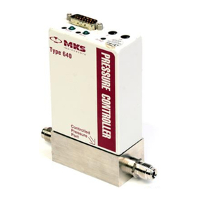
MKS Convectron 316 Series User manual

Series 316
Instruction Manual
Convectron®Vacuum Gauge
Controller
Instruction manual part number 316059
Revision D - March 2020


Instruction Manual
Series 316
This Instruction Manual is for use with Granville-Phillips
Series 316 Convectron Gauge Controllers, catalog numbers
20316046 and 316035.
© 2020 MKS Instruments, Inc. All rights reserved.
Granville-Phillips®and Convectron®are registered trademarks, and mksinstTM is a trademark
of MKS Instruments, Inc. All other trademarks and registered trademarks are the properties of
their respective owners.
Convectron®Vacuum Gauge
Controller
Customer Service / Technical Support:
MKS Global Headquarters
2 Tech Drive, Suite 201
Andover MA, 01810 USA
Phone: +1-833-986-1686
Email: insidesales@mksinst.com
Visit our website at www.mksinst.com

Catalog numbers for Granville-Phillips®
Convectron®Vacuum Gauge Controller
20316046 and 316035

Series 316 Vacuum Gauge Controller Installation and Operation Instructions
P/N 316059 5
Table of Contents
Safety
Section 1 - The 316 Vacuum Gauge Controller
1.1 Introduction . . . . . . . . . . . . . . . . . . . . . . . . . . . . . . . . . . . . . . . . . . . . . . . . . . . . 1-1
1.2 Available Configurations . . . . . . . . . . . . . . . . . . . . . . . . . . . . . . . . . . . . . . . . . . 1-1
1.2.1 Convectron Gauge (CG) Module . . . . . . . . . . . . . . . . . . . . . . . . . . . . . . . 1-1
1.3 Installation . . . . . . . . . . . . . . . . . . . . . . . . . . . . . . . . . . . . . . . . . . . . . . . . . . . . . 1-1
1.3.1 Line Voltage Selection . . . . . . . . . . . . . . . . . . . . . . . . . . . . . . . . . . . . . . . 1-1
1.3.2 Mounting Configurations. . . . . . . . . . . . . . . . . . . . . . . . . . . . . . . . . . . 1-3
1.3.3 Cable Connections . . . . . . . . . . . . . . . . . . . . . . . . . . . . . . . . . . . . . . . . . . 1-5
1.3.3 Instrument Grounding . . . . . . . . . . . . . . . . . . . . . . . . . . . . . . . . . . . . . . . . 1-5
1.4 Summary of Controls and Indicators . . . . . . . . . . . . . . . . . . . . . . . . . . . . . . . . . 1-6
1.5 Theory Of Operation . . . . . . . . . . . . . . . . . . . . . . . . . . . . . . . . . . . . . . . . . . . . . 1-7
1.5.1 Microcontrollers and Bus Structure . . . . . . . . . . . . . . . . . . . . . . . . . . . . . 1-7
1.5.2 Gauge Theory . . . . . . . . . . . . . . . . . . . . . . . . . . . . . . . . . . . . . . . . . . . . . . 1-7
1.6 Calibration . . . . . . . . . . . . . . . . . . . . . . . . . . . . . . . . . . . . . . . . . . . . . . . . . . . . . 1-7
1.7 Basic 316 VGC Troubleshooting . . . . . . . . . . . . . . . . . . . . . . . . . . . . . . . . . . . . 1-7
1.7.1 Guidelines . . . . . . . . . . . . . . . . . . . . . . . . . . . . . . . . . . . . . . . . . . . . . . . . . 1-7
1.8 Service Guidelines . . . . . . . . . . . . . . . . . . . . . . . . . . . . . . . . . . . . . . . . . . . . . . 1-10
1.9 Specifications . . . . . . . . . . . . . . . . . . . . . . . . . . . . . . . . . . . . . . . . . . . . . . . . . . 1-10
Section 2 - The Convectron Gauge Module
2.1 Safety . . . . . . . . . . . . . . . . . . . . . . . . . . . . . . . . . . . . . . . . . . . . . . . . . . . . . . . . . 2-1
2.1.2 Explosive Gases . . . . . . . . . . . . . . . . . . . . . . . . . . . . . . . . . . . . . . . . . . . . 2-1
2.1.3 Limitation on Use of Compression Mounts . . . . . . . . . . . . . . . . . . . . . . . 2-1
2.1.4 Tube Mounting Position . . . . . . . . . . . . . . . . . . . . . . . . . . . . . . . . . . . . . . 2-1
2.1.5 Overpressure . . . . . . . . . . . . . . . . . . . . . . . . . . . . . . . . . . . . . . . . . . . . . . . 2-1
2.1.6 High Indicated Pressure . . . . . . . . . . . . . . . . . . . . . . . . . . . . . . . . . . . . . . 2-2
2.1.7 Chemical . . . . . . . . . . . . . . . . . . . . . . . . . . . . . . . . . . . . . . . . . . . . . . . . . . 2-2
2.1.8 Sensor Failure . . . . . . . . . . . . . . . . . . . . . . . . . . . . . . . . . . . . . . . . . . . . . . 2-2
2.1.9 Tube Contamination . . . . . . . . . . . . . . . . . . . . . . . . . . . . . . . . . . . . . . . . . 2-3
2.2 Convectron Module Introduction . . . . . . . . . . . . . . . . . . . . . . . . . . . . . . . . . . . . 2-3
2.2 Convectron Installation . . . . . . . . . . . . . . . . . . . . . . . . . . . . . . . . . . . . . . . . 2-3
2.2.1 Convectron Gauge Tube Installation. . . . . . . . . . . . . . . . . . . . . . . . . . 2-3
2.2.2 Gauge Tube Orientation. . . . . . . . . . . . . . . . . . . . . . . . . . . . . . . . . . . . 2-4
2.2.4 Compression Mount (Quick Connect). . . . . . . . . . . . . . . . . . . . . . . . . 2-6
2.2.5 1/8 NPT Mount . . . . . . . . . . . . . . . . . . . . . . . . . . . . . . . . . . . . . . . . . . 2-6
2.2.6 NW16KF Flange Mount . . . . . . . . . . . . . . . . . . . . . . . . . . . . . . . . . . . 2-6
2.2.7 Other Mounting Options . . . . . . . . . . . . . . . . . . . . . . . . . . . . . . . . . . . 2-6
2.3 Convectron Operation . . . . . . . . . . . . . . . . . . . . . . . . . . . . . . . . . . . . . . . . . . . . 2-7
Series 316 Vacuum Gauge Controller Installation and Operation Instructions
6P/N 316059
Table of Contents (continued)
2.3.1 Reading Pressure . . . . . . . . . . . . . . . . . . . . . . . . . . . . . . . . . . . . . . . . . . . . 2-7
2.3.2 Special Considerations For Use Below 10 -3 Torr . . . . . . . . . . . . . . . . . . 2-7
2.3.3 Use With Gases Other Than N2 and Air . . . . . . . . . . . . . . . . . . . . . . . . . 2-8
2.3.4 Indicated vs. True Pressure Curves . . . . . . . . . . . . . . . . . . . . . . . . . . . . . . 2-8
2.3.5 Example 1 - Maximum Safe Indicated Pressure . . . . . . . . . . . . . . . . . 2-9
2.3.6 Example 2 - Indicated to True Pressure Conversion . . . . . . . . . . . . . . 2-9
2.3.7 Example 3 - True to Indicated Pressure Conversion . . . . . . . . . . . . . 2-10
2.3.8 Example 4 - True to Indicated Pressure Conversion . . . . . . . . . . . . . 2-17
2.4 Analog Output . . . . . . . . . . . . . . . . . . . . . . . . . . . . . . . . . . . . . . . . . . . . . . . . . 2-17
2.5 Convectron Calibration and Maintenance . . . . . . . . . . . . . . . . . . . . . . . . . . . . 2-18
2.5.1 Zero Adjustment . . . . . . . . . . . . . . . . . . . . . . . . . . . . . . . . . . . . . . . . . . . 2-19
2.5.2 Atmosphere Adjustment . . . . . . . . . . . . . . . . . . . . . . . . . . . . . . . . . . . . . 2-19
2.5.3 Analog Output Full Scale Adjustment . . . . . . . . . . . . . . . . . . . . . . . . . . 2-20
2.5.4 Analog Output Offset . . . . . . . . . . . . . . . . . . . . . . . . . . . . . . . . . . . . . . . 2-20
2.6 Cleaning the Gauge Tube . . . . . . . . . . . . . . . . . . . . . . . . . . . . . . . . . . . . . . . . 2-21
2.7 Theory of Operation . . . . . . . . . . . . . . . . . . . . . . . . . . . . . . . . . . . . . . . . . . . . . 2-22
2.8 Convectron Troubleshooting . . . . . . . . . . . . . . . . . . . . . . . . . . . . . . . . . . . . . . 2-23
2.8.1 Transducer Test Procedure . . . . . . . . . . . . . . . . . . . . . . . . . . . . . . . . . . . 2-23
3.0 Convectron Specifications . . . . . . . . . . . . . . . . . . . . . . . . . . . . . . . . . . . . . . . . 2-28
Appendix A - Customer Support Centers
Figures
Figure 1-1: Line Voltage Select Jumpers, Power Supply PC Board . . . . . . . . . 1-2
Figure 1-2: Mounting Configurations . . . . . . . . . . . . . . . . . . . . . . . . . . . . . . . . 1-4
Figure 1-3: 316 VGC Cable Connections . . . . . . . . . . . . . . . . . . . . . . . . . . . . . 1-5
Figure 1-4: Correct System Grounding . . . . . . . . . . . . . . . . . . . . . . . . . . . . . . . 1-6
Figure 1-5: 316 VGC Control Unit Front Panel . . . . . . . . . . . . . . . . . . . . . . . . 1-6
Figure 1-6: Power Supply Board Top View . . . . . . . . . . . . . . . . . . . . . . . . . . . 1-9
Figure 2-1: Convectron Gauge Mounting . . . . . . . . . . . . . . . . . . . . . . . . . . . . . 2-5
Figure 2-2: Indicated Pressure of a Convectron Gauge (1 to 100 mTorr) . . . . 2-11
Figure 2-3: Indicated Pressure of a Convectron Gauge (0.1 to 1000 Torr) . . . 2-12
Figure 2-4: Indicated Pressure of a Convectron Gauge (0.1 to 1000 Torr) . . . 2-13
Figure 2-5: Indicated Pressure of a Convectron Gauge (10-3 to 10-1 mbar) . 2-14
Figure 2-6: Indicated Pressure of a Convectron Gauge (0.1 to 1000mbar) . . . 2-15
Figure 2-7: Indicated Pressure of a Convectron Gauge (0.1 to 1000 mbar) . . 2-16

Series 316 Vacuum Gauge Controller Installation and Operation Instructions
P/N 316059 7
Table of Contents (continued)
Figure 2-8: Convectron Module Rear Panel . . . . . . . . . . . . . . . . . . . . . . . . . . 2-17
Figure 2-9: Convectron Gauge Pressure Analog Output . . . . . . . . . . . . . . . . . 2-18
Figure 2-10: Convectron Modules Front Panel . . . . . . . . . . . . . . . . . . . . . . . . 2-19
Figure 2-11: Convectron Modules Top View . . . . . . . . . . . . . . . . . . . . . . . . . 2-20
Figure 2-12: Simplified Schematic Convectron Gauge Module . . . . . . . . . . . 2-22
Figure 2-13: Convectron Module, Top view . . . . . . . . . . . . . . . . . . . . . . . . . . 2-25
Figure 2-14: Convectron Cable Wiring (Single Filament) . . . . . . . . . . . . . . . 2-26
Figure 2-15: Convectron Cable Wiring (Dual Filament) . . . . . . . . . . . . . . . . . 2-27
Tables
Table 1-1: 316 VGC Troubleshooting . . . . . . . . . . . . . . . . . . . . . . . . . . . . . . . . 1-9
Table 1-2: 316 VGC Physical Specifications . . . . . . . . . . . . . . . . . . . . . . . . . 1-10
Table 1-3: 316 VGC Electrical Specifications . . . . . . . . . . . . . . . . . . . . . . . . 1-11
Table 2-1: True Pressure vs. Indicated Pressure Figures . . . . . . . . . . . . . . . . . . 2-8
Table 2-2: 275 Transducer Pin Resistance . . . . . . . . . . . . . . . . . . . . . . . . . . . 2-23
Table 2-3: Convectron Troubleshooting Guide . . . . . . . . . . . . . . . . . . . . . . . . 2-23
Table 2-4: Convectron Specifications . . . . . . . . . . . . . . . . . . . . . . . . . . . . . . . 2-28
Table A-1: Customer Support Centers . . . . . . . . . . . . . . . . . . . . . . . . . . . . . . . . A-2

Series 316 Vacuum Gauge Controller Installation and Operation Instructions
8P/N 316059

Series 316 Vacuum Gauge Controller Installation and Operation Instructions
P/N 316059 1-1
Section 1 - The 316 Vacuum Gauge Controller
1.1 Introduction
The 316 Vacuum Gauge Controller (VGC) measures pressures from
1 x 10⁻⁴ Torr (1 x 10⁻⁴ mbar or 1 x 10⁻² Pa) to atmosphere, depending on
modules and transducers used.
Modules are available to operate Convectron, capacitance manometer, and
thermocouple gauges with three pressures displayed simultaneously.
Pressure readout is via 3 front panel displays, analog output, and available
computer interface.
The 316 VGC is a modular instrument which can be easily customized to
fit most user's exact needs. Infrequently used controls are housed behind a
hinged front panel, reducing front panel clutter and allowing the control
unit to reside in a half-rack space.
1.2 Available Configurations
1.2.1 Convectron Gauge (CG) Module
Permits pressure measurements from 1 x 10⁻⁴ to 999 Torr of N2from up to
three MKS Series 275 Convectron Gauges simultaneously provides analog
output of each indicated pressure.
1.3 Installation
1.3.1 Line Voltage Selection
Line voltages of 90-110 or 105-125 or 220-240 volts are user selectable via
jumpers on the power supply PC board within the controller. The factory
preset line voltage and fuse rating are marked on the rear panel. Compare
your unit to Figure 1-1 to determine if it is configured for your
requirements. Do not apply power until the correct configuration is
achieved.

The 316 Vacuum Gauge Controller
1-2 P/N 316059
Figure 1-1: Line Voltage Select Jumpers, Power Supply PC Board
316 POWER SUPPLY
009425-100
100/
100
115
100/
115
115/230
LINE VOLTAGE
LED
100/
115
115
100/
115
115
100/
230
100
100/
115/230
230
100
100/
115
115/230
230
100
100/
115
115/230
100VAC230VAC115VAC
230
HOLDER
FUSE
IEC
CONN
1
4
2
3
5
6
7
8
3
1
2
1
10
4
1
3
2
4
1
3
2

Series 316 Vacuum Gauge Controller Installation and Operation Instructions
P/N 316059 1-3
1.3.2 Mounting Configurations
NOTE: The 316 controller should be mounted in a location with free air
flow and ambient temperature less then 40 oC.
NOTE: Figure 1-2 illustrates the various configurations available for
mounting the 316 control unit and power supply.
NOTE: When installing a mounting ear 8 into the left side of the control
unit, the door should be open.
The bracket (Figure 1-2, item 9) used to connect two control units for side
by side rack mounting is not symmetrical. Install as shown.
The rear support bracket assembly consists of a U-shaped bracket (Figure
1-2, item 7) and two spring clamps (Figure 1-2, item 6) which grip into
grooves in the side of the control unit.

The 316 Vacuum Gauge Controller
1-4 P/N 316059
Figure 1-2: Mounting Configurations
18.3
19.0
3.0
3.5
3.5
3.0
11.0
8.8
9.5
8.0
2 CONTROL UNIT MOUNTING ADAPTER
307021
1/2 RACK
316002
316001
CONTROL UNIT
7
REAR VIEW
CONTROL UNIT CONTROL UNIT
6
CONTROL UNIT
MOUNTING EAR
CONTROL UNIT
FRONT OF
SIDE OF
SCREW (2X)
8-32X.25
8
9
CONTROL UNIT
307010
MOUNTING
OFFSET RACK
307022
CONTROL UNIT
BENCH MOUNT
8.0
CONTROL UNIT
307011
MOUNTING
CENTER RACK
11.0

Series 316 Vacuum Gauge Controller Installation and Operation Instructions
P/N 316059 1-5
1.3.3 Cable Connections
To avoid confusion in cable connections, a set of labels is provided with the
cable. The labels are easily attached to the gauge connector with the
adhesive backing. The rear panels of the Convectron and thermocouple
modules are labeled with their respective display designations, A, B and C.
See Figure 1-3 for cable connections. Tighten screws to secure connectors.
Figure 1-3: 316 VGC Cable Connections
1.3.3 Instrument Grounding
For safe operation, the VGC controller must be connected to an AC power
source which includes a ground wire. This power ground is generally a
sufficient safety precaution. A grounding stud is provided on the rear panel
of the power supply module should the user require a separate earth
ground. We recommend that you ground all metal parts of your vacuum
system separately to power or earth ground. Do not ground the system via
a wire to the 316 chassis. Refer to Figure 1-4.
NOTE: The metal case of the gauge tube does not connect to the controller
ground. Electrical connection of the gauge tube envelope to the system
does not cause a ground connection between the system and the controller.
VGC
REAR
PANEL
(OR T.C.)TUBE
CONVECTRON A
(OR T.C.)TUBE
CONVECTRON
(OR T.C.)CABLE
1 CHANNEL
CONVECTRON C
OR
CAPACITANCE MANOMETER
CONVECTRON B
(OR T.C.)TUBE
8
A
G
E
U
15
ANALOG
OUTPUT A
1C
C
T
G
9
GG
OUTPUT C
ANALOG
8
G
E
U
A
15
OUTPUT B
19
C
G
C
T
M
C
ANALOG
G
A
8
ANALOG
OUTPUT C
815
U
E
G
15
A
U
E
G
OUTPUT A
1919
G
G
T
C
C
C
M
T
C
G
C
ANALOG ANALOG
OUTPUT B

The 316 Vacuum Gauge Controller
1-6 P/N 316059
Figure 1-4: Correct System Grounding
1.4 Summary of Controls and Indicators
A description of the controls and indicators found on a basic 316 VGC is
given in this section.
Figure 1-5: 316 VGC Control Unit Front Panel
SYSTEM
ELECTRODE
GROUNDING
FACILITY
2
WIRE
GROUNDING
CAPACITY SAFETY GROUNDING
GROUNDING ELECTRODE SYSTEM
(12 AWG (2.05 mm )MIN.).
LEADS ARE NOT SHOWN
CHASSIS TO FACILITY
WIRE FROM CONTROLLER
INSTALL HIGH CURRENT
NOTE : OTHER POWER
CONTROLLER
ION GAUGE
GROUND WIRE
VACUUM SYSTEM
POWER DISTRIBUTION
BREAKER BOX
DO
NOT
MAKE DIRECT CHASSIS TO VACUUM
SYSTEM CONNECTION!
POWER COMMON OR SAFETY
GROUNDING WIRE. 12 AWG
2
(2.05 mm ) MINIMUM SIZE.
POWER
ONOFF
11

Series 316 Vacuum Gauge Controller Installation and Operation Instructions
P/N 316059 1-7
1.5 Theory of Operation
1.5.1 Microcontrollers and Bus Structure
Each module in the 316 has a dedicated microcontroller with internal
ROM, RAM, timing, and interrupt management functions. This
architecture provides high-performance at low cost with greater reliability
and noise immunity than more complicated microprocessor systems using
external buses and memory.
Each microcontroller is equipped with a watchdog timer, which
automatically generates a reset if the processor fails to fulfill timing
"checkpoints" within its code.
Inter-processor communication is accomplished via the display bus. These
lines carry BCD-format pressure data which is used to generate the 316
display. The bus is updated once per millisecond. Out of every sixteen
cycles, fifteen cycles are used for display data, and one is reserved for
inter-processor communication. Modules that require pressure data, such as
process control and computer interface, take it directly from the display
update cycles.
1.5.2 Gauge Theory
The Convectron gauge is a heat loss transducer. This causes the response
of the gauges to be gas type dependent and non-linear. The Convectron
gauge uses feedback amplifier circuitry to maintain the sensor at a constant
temperature thus providing greater resolution over a wider pressure range.
More detailed explanations of the theory of operation of the Convectron
gauge can be found in section 2.5.
1.6 Calibration
Calibration instructions for each gauge module are contained in the chapter
for that module. Convectron gauge calibration is in section 2.5.
1.7 Basic 316 VGC Troubleshooting
1.7.1 Guidelines
Further troubleshooting information is located in the chapters for specific
modules. The 316 VGC has been designed for easy repair by replacement
of modules. If the user elects to perform repairs at the component level,
repairs properly made with equivalent electronic parts and rosin core solder
do not represent a violation of the warranty.

The 316 Vacuum Gauge Controller
1-8 P/N 316059
Some minor difficulties are user correctable, and the built-in diagnostic
aids described here may be helpful.
Each module has status LEDs which will aid in localizing failures. These
are described in the troubleshooting section of the chapters for each
module. Shown in Figure 1-6 are those LEDs found on the 316 VGC
power supply board. This is the PC board on the right side (when viewed
from the front) of the 316 control unit.
Since the 316 VGC contains static-sensitive electronic parts, the following
precautions must be followed when troubleshooting:
a. Use a grounded, conductive work surface.
b. Use conductive envelopes to store or ship MOS devices or
printed circuit boards.
c. Do not operate the 316 VGC with MOS devices removed
from the unit.
d. Do not handle MOS devices more than absolutely
necessary, and only when wearing a ground strap.
e. Do not use an ohmmeter for troubleshooting. Rely on
voltage measurements.
f. Use grounded-type soldering iron only.
WARNING
High voltages are present within the controller capable of causing injury
or death. Do not touch cable connections or circuitry of the power supply
module when power is applied.

Series 316 Vacuum Gauge Controller Installation and Operation Instructions
P/N 316059 1-9
Figure 1-6: Power Supply Board Top View
Table 1-1: 316 VGC Troubleshooting
Symptom Possible Cause
Unit won't power-up, no response to
power switch. Power fuse 17 blown.*
Power fuse 17 blows repeatedly.* 1. Wrong line voltage selection, see Figure 1-1.
2. Wrong fuse rating.
3. Wrong line voltage selection, see Figure 1-1.
LED 12 out on control board.* +15 volt supply faulty (power to capacitance
manometer).
LED 13 out.* +12 volt supply faulty (power to analog circuitry
and RS232).
LED 14 out.* +5 volt supply faulty (power to logic and display).
LED 15 out.* -12 volt power faulty (power to analog circuitry
and RS232).
LED 16 out.* -15 volt supply faulty (power to capacitance
manometer).
* Refer to Figure 1-6 for component location.

The 316 Vacuum Gauge Controller
1-10 P/N 316059
1.8 Service Guidelines
Some minor problems are readily corrected on site. If the product requires service,
contact the MKS Technical Support Department at +1-833-986-1686. If the prod-
uct must be returned to the factory for service, request a Return Material Authori-
zation (RMA) from MKS. Do not return products without first obtaining an RMA.
In some cases a hazardous materials disclosure form may be required. The MKS
Customer Service Representative will advise you if the hazardous materials docu-
ment is required.
When returning products to MKS, be sure to package the products to prevent ship-
ping damage. Shipping damage on returned products as a result of inadequate
packaging is the Buyer's responsibility.
For Customer Service / Technical Support:
MKS Global Headquarters
2 Tech Drive, Suite 201
Andover MA, 01810 USA
Phone: +1-833-986-1686
Email: [email protected]
Visit our website at: www.mksinst.com1.9 Specifications
See the chapters for each module for additional specifications relating to that
module.
Table 1-2: 316 VGC Physical Specifications
Parameter Value
Width 241 mm (9.5 in.) with 1/2 rack mounting ears.
Height 89 mm (3.5 in.)
Depth 356 mm (14 in.) includes 76 mm (3 in.) for connectors
and cables.
Weight 3 kg (6.5 lb.)
Environmental Operating
Temperature 0oC to 40 oC

Series 316 Vacuum Gauge Controller Installation and Operation Instructions
P/N 316059 1-11
Table 1-3: 316 VGC Electrical Specifications
Parameter Value
Voltage 90-110 VAC or 105-125 VAC
Frequency 50 or 60 Hz
Power 100 watts max.
Fuse Ratings 0.5 A (90-125 VAC), 3AG normal blow
0.25 A (220-240 VAC), 3AG normal blow

The 316 Vacuum Gauge Controller
1-12 P/N 316059
This manual suits for next models
2
Table of contents
Other MKS Controllers manuals