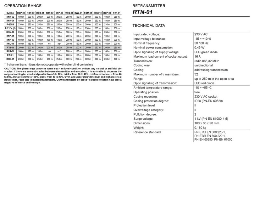
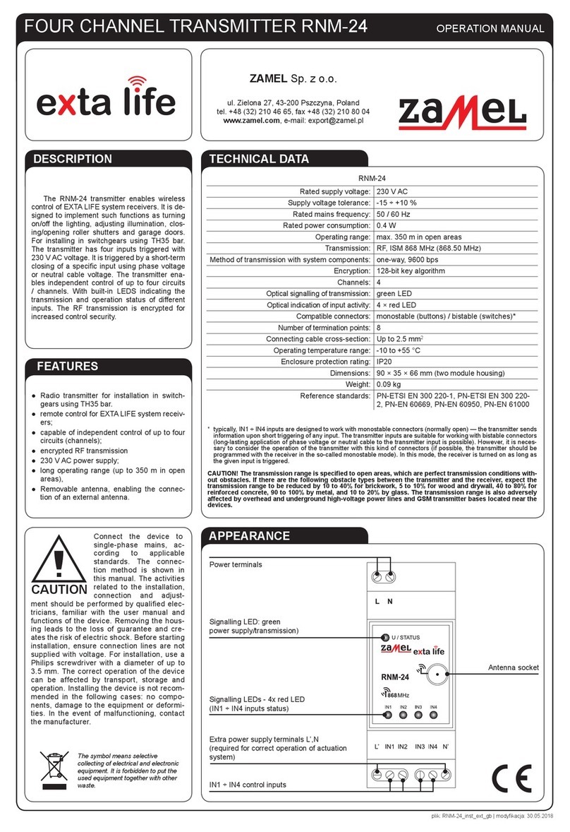
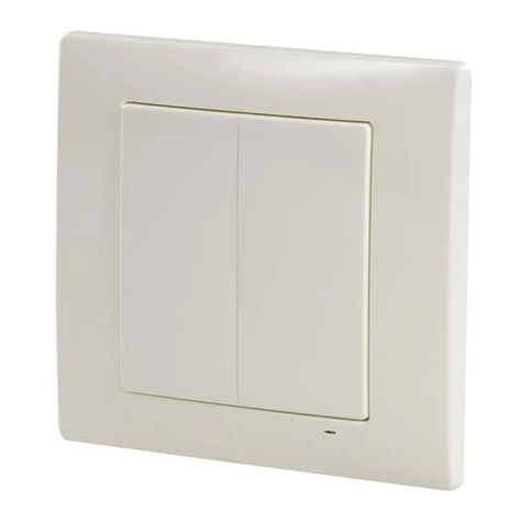
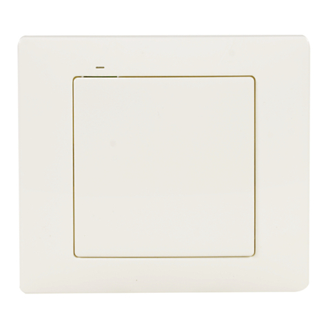
Zamel exta life RNK-22 User manual

2-CHANNEL BUTTON TRANSMITTER WITH TEMPERATURE SENSOR
RNK-22
TECHNICAL DATA
DESCRIPTION
The RNK-22 wall radio transmitter is used to send control signals and temperature value
related information in the extalife system. It is applied to realise the following functions:
switching on/switching off, brightening/dimming, roller blind control. The implemented frame
coding algorithm increases the safety of the transmission. Temperature value is displayed in
the mobile application due to the cooperation of the transmitter with EXTA LIFE controller.
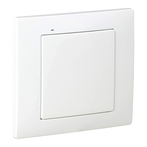
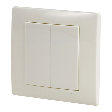
The transmitter resembles a common switch due to its appearance and dimensions. The
battery backup and lack of wiring allows for its wide application. It means the transmitter can
be mounted on any surface (excluding metal surface) and in any place. By assigning a few
controllers to one transmitter it is possible to control the device independently from different
locations. During operation the LED green informs the transmission is in progress. The LED
diode is also used to signal battery discharge.
Nominal supply voltage: 3 V DC
Battery type: CR2032
Battery operating life: 2 ÷ 3 years with switched on temperature sensor
3 ÷ 5 years with switched off temperature sensor
Number of channels: 2
Transmission: radio - ISM 868 MHz band
Transmission way: One-way - 9600 bps
Coding: Algorithm based upon 128-bit key
Cooperation: only with exta life elements
Operating range to 300 m in the open area
Ambient temperature measuring
range:
-40 ÷ +125 °C – it is a complete measuring range of the applied
temperature sensor. It is required to obey the recommended operating
temperature of the RNK-22 transmitter.
Measuring resolution: 0,1 °C
Measuring accuracy: ±1 °C (type) 0°C ÷ +85°C / ±2 °C (type) -40°C ÷ +125°C
Temperature measuring frequency: every 15 minutes
Battery charge/discharge optical
signalling: LED green
Temperature operating range: -10 ÷ +55 °C
Operating position: free
Casing mounting: wall plugs, double-sided adhesive tape
Casing protection degree: IP20 (EN 60529)
Protection level: III
Pollution degree: 2
Dimensions: 90 x 80 x 11,5 mm
Weight: 0,038 kg
Reference standard: ETSI EN 300 220-1, ETSI EN 300 220-2

FEATURES
FUNCTIONING
APPEARANCE
● 1-button(2-channel)radiotransmitter,
● remotecontrolofextalifesystemreceivers,
● possibilityofindependentcontroloftworeceivers,
● codedradiotransmission,
● integratedinnertemperaturesensor,
● temperaturemeasurementrealisedbymeansofasensor:-40÷+125°C,
● batterypowered,
● charge/dischargebatteryopticalsignalling
● wideoperationrange(upto300mintheopenarea).
By pressing the button, the transmitter sends a radio signal to exta life system elements.
The above is signalled by a blinking LED green in the transmitter. It is important that the
transmitter and the receivers are paired correctly, so that the cooperation between them is
undisturbed. Device pairing procedure (adding a transmitter to a receiver’s memory) is pre-
cisely described in particular EXTA LIFE instruction manual. The transmitter sends a signal
only while pushing / releasing the button. In case the button is pushed, the radio signal is
not sent. The above protects against quick battery discharge. Whereas temperature value
issenteveryfthpressingofanybuttonorautomaticallydependingoncurrentconditions
in the mounting place.
Optical signalling of transmitter’s operation
Button
Base
Temperature sensor

MOUNTING
The RNK-22 transmitter is mounted on walls by means of a double-adhesive tape or wall
plugs included in the kit with a transmitter. During mounting it is important to protect the
transmitter from water and operation in humid conditions. The ambient temperature during
installation should be from -10 do +55°C.
While mounting the transmitter with a built-in temperature sensor, it is important to
pay attention not to mount the transmitter in direct sunshine or frequent air move-
ments. It must be installed at a proper height.
Mounting by means of wall plugs:
1. Remove the button - to do it press the button on one side, and on the other side put a
screwdriver into a slot and lift up the button.
2. Find a place on the wall to mount the transmitter, make two holes corresponding mounting
holes of the transmitter’s base.
3. Set wall plugs in the holes.
4. Fix the base by means of screws into wall plugs.
5. Place the button again.
27 mm
23 mm
17,5 mm
45 mm
45 mm
Suggested places
for the double-adhesive
tape
Caution:
● itisbesttouse5x(3x30)mmwallplugs,
● optimumdouble-adhesivetapethicknessis1,2mm,
● wallplugsanddouble-adhesivetapeareincludedinthekitwithatransmitter.
20 mm

BATTERY CHANGE
Battery discharge status is signalled by sev-
eral LED red ashes during transmission is in
progress. In case the transmitter is paired with
a controller, the battery discharge status is
displayed in the mobile application in the form
of a message. The transmitter signals the bat-
tery must be changed when its voltage drops
below the <2.1 V value. The signal is cancelled
only after the battery change.
1. Remove the button by means of a at screw-
driver (Fig. 1).
2. By means of a screwdriver lever up the printed-
circuit board releasing the bottom latch and re-
move it from the base (Fig. 2).
3. Remove the battery from the latch (Fig. 3).
4. Press any button of the transmitter a few times
(to fully discharge).
5. Mount a new battery. Watch battery polarisa-
tion marked on the latch (potential „+”).
CAUTION: Wrong battery mounting may cause device damage.
6. Put the removed printed-circuit board back in the base.
7. Put back the button.
8. Check correct operation – LED diode should switch on in the same way as during trans-
mission.
Fig. 1
Fig. 2 Fig. 3
Battery discharge status in application exta life.

SAFE USE CAUTIONS
STANDARD FUNCTIONALITY
● standardfunctionalityallowsdirectcontroloftheextalifesystemreceivers,
●transmitter’sbuttonfunctionalitydependsonthetypeofareceiverthebuttonshavebeen
paired with (for example, when paired with ROP-22 receiver, the buttons can be used to
switch on / switch off the lighting and when paired with SRP-22 roller blind controller, the
buttons can be used to open / close roller blinds),
●particularbuttonscanbeassignedtoahighernumberofextalifesystemreceiversatthe
same time,
● in case one transmitter is to control more than one system receiver, the recommended
operation mode is the „switch on / switch off” mode (one button is used to switch on and
the second to switch off),
●itispossibletoassigntransmitter’sbuttonstoreceiversindifferentmodes,whichdepend
on the type of a receiver (details are described in the instruction manuals of exta life
receivers),
●incasebuttonsofonetransmitterareassignedtoareceiverintimemode,thenitispos-
sible to assign individual time in the range from 1 second to 18 hours to each button,
●buttonscanbeselectivelydeletedfromthememoryofreceivers
FUNCTIONALITY WITH CONTROLLER AND EXTA LIFE APPLICTION
Using EXTA LIFE controller and the mobile application it is possible to
● assignremotely(withoutanaccesstoareceiver)buttonsofatransmittertoselectedre-
ceivers,
●usetransmitter’sbuttonstoperformscenes–
or as a condition to perform the logic function,
●controlbatterystatusinthetransmitter,
●readtemperaturefromasensorbuilt-inatransmitter.
CAUTION: in order to make use of the functionalities, it is required to pair transmitter
with a controller earlier and to register the temperature sensor in the system.

TEMPERATURE SENSOR FUNCTIONALITY
Temperature sensor used in RNK-22 is a digital sensor. It enables to measure temperature in
the following range: -40 to +125°C.
CAUTION:
● Temperature operating range of the RNK-22 transmitter is between -10 to +55°C,
that is why it should not be applied to measure temperature exceeding this range.
● Measuring characteristics excludes the application of the sensor in rooms with
a dynamic temperature change (the sensor does not register quick temperature
changes).
By default, temperature sensor in the transmitter is switched on. The sensor can be switched
off if not used by a user (see Temperature sensor switching on / switching off). Switching off
the sensor prolongs the battery life.
MEASUREMENT CHARACTERISTICS
The sensor measurement differential is set to ± 0.3 ° C without the possibility of change.
Temperaturemeasurementissenttothecontrolleralwaysafterthefthpressofanybutton
of the transmitter with a delay of 5 s (temperature is measured and sent after 5 seconds from
thedetectionofthefthpressing).
During standard operation, temperature measurement is performed approximately every 15
minutes. The measured temperature (T2) is compared with the previous measurement (T1)
and according to the difference of the two values, the current measurement is sent to the
controller or not.
T2 – T1 > 0,3°C – the measurement is sent to the controller to update the value
T2–T1≤0,3°C–themeasurementisnotsenttothecontroller
If the room temperature is stable and changes its value during the next 19 measurements by
≤0.3°C(T2-T1≤0.3°C),thenafterperformingthetwentiethmeasurement(afteraround
300 minutes) the temperature is obligatorily sent to the controller to update. Sending tem-
peratureaftertheobligatorytimeissignalledbyaashingLEDinthetransmitter.
SWITCHING ON / SWITCHING OFF TEMPERATURE SENSOR
Switching off the temperature sensor
By default, the temperature sensor is switched on in the
RNK-24 transmitter. In order to switch it off, carry out the
following:
1. Take the battery out of a transmitter.
2. Press button “2” of the transmitter.
3. While pressing button “2” insert the battery into the
transmitter.
4. Release button “2” of the transmitter.
5. Temperature sensor is switched off.
The switched off sensor in the transmitter is remembered
even after the battery is taken out. In order to switch it on
carry out activities described in “Switching on the temperature sensor”.
ADDING TEMPERATURE SENSOR IN EXTA LIFE SYSTEM
Adding a sensor into the exta life system requires the connection of the EXTA LIFE controller
and the installation of extalife application in a mobile device.
In order to pair a sensor with a controller the follow-
ing is required:
1. Start extalife application.
2. Enter the “Device” screen.
3. Choose the “Sensors” tab.
4. Enter the search screen by pressing the “+” but-
ton.
5. In time shorter than 60 seconds it is required to
press any button of the transmitter 5 times. After
that wait for a few seconds.
6. The temperature sensor is registered on the
sensor list waiting for pairing with the controller.
7. Before another 60 seconds elapse, the next
temperature sensors can be registered or the
search process can be stopped by pressing the
“Stop” button.
8. Afterthesensorsearchisnished,itisrequired
to mark the sensors we want to add in the con-
troller and press the “Pair” button.
9. Aftertheaboveprocedureisnishedthesensor
is visible in the system and it can show the tem-
perature registered during the pairing process.
It is possible to assign a name to the sensor, an
icon and use it in the mobile application.
Caution: The application temperature is updat-
ed each time we enter the screen by the sensor
or each time we refresh the screen manually
(drag the screen downward).
Switching on the temperature sensor
In order to switch on the temperature sensor, carry out the
following:
1. Take the battery out of a transmitter.
2. Press button “1” of the transmitter.
3. While pressing button “1” insert the battery into the
transmitter.
4. Release button “1” of the transmitter.
5. Temperature sensor is switched on.

COOPERATION AND OPERATING RANGE
CAUTION! The given range concerns the open area - an ideal condition without any
natural or articial obstacles. If there are some obstacles between a transmitter and
a receiver, it is advisable to decrease the range according to: bricks from 10 to 40 %,
wood and plaster from 5 to 20 %, reinforced concrete from 40 to 80 %, metal from 90 to
100%, glass from 10 to 20 %. Over- and underground medium and high electrical power
lines, radio and television transmitters, GSM transmitters set close to a device system
have also a negative inuence on the range.
ROP-21 ROP-22 RDP-21 SRP-22 EFC-01
RNK-22 280 m 300 m 280 m 300 m 350 m
RNK-24 280 m 300 m 280 m 300 m 350 m
P-457/2 280 m 300 m 280 m 300 m 350 m
P-457/4 280 m 300 m 280 m 300 m 350 m
EFC-01 330 m 350 m 330 m 350 m -
Other manuals for exta life RNK-22
1
Table of contents
Other Zamel Transmitter manuals

Zamel
Zamel RNK-04 User manual

Zamel
Zamel ROP-01 User manual

Zamel
Zamel RNL-01 User manual

Zamel
Zamel EXTA FREE RNK-04 User manual

Zamel
Zamel exta life RNK-22 User manual

Zamel
Zamel EXTA LIFE RNM-24 User manual

Zamel
Zamel RNK-02 User manual

Zamel
Zamel EXTA LIFE RNP-21 User manual

Zamel
Zamel PDH-250 User manual

Zamel
Zamel RNP-22 User manual
Popular Transmitter manuals by other brands

Ashcroft
Ashcroft ZT12 Installation and maintenance instructions

Thies CLIMA
Thies CLIMA 4.3515.30.000 Instructions for use

Williams Sound
Williams Sound IR T01 user manual

Masibus
Masibus UT-94 user manual

Turnigy
Turnigy 9XR-PRO Communications guide

Nice
Nice DTX6 Instructions and warnings for installation and use