ZCS 20000TL-G2 User manual

PV Grid-Connected Inverter
User manual
www.zcsazzurro.com
Add
Product Model: 20K-33KTL-G2 (2018.10.08)

Notice
The product , service and features that you purchased are bound by ZCS commercial contract
and terms,The product, service and features(or part of them) described in this document
may not be in your purchase or usage range. ZCS does not declare or guarantee any content
in this document except there are other contractual stipulation.
Save these instructions!
This manual must be considered as an integral part of the equipment, and must be available
at all times to everyone who interacts with the equipment. The manual must always
accompany the equipment, even when it is transferred to another user or field.
Copyright Declaration
I
Preface
Please read the product manual carefully before installation, operation or maintenance. This
manual contains important safety instructions and installation instructions that must be
followed during installation and maintenance of the equipment.
This manual is for qualified person (support person, service person are qualified mentioned in
this manual).
Outline
Scope
Target Group
Symbols Used
This manual provides safety operation information and uses the symbol in order to ensure
personal and property security and use the inverter efficiently when operating the inverter.
You must understand these emphasized information to avoid the personal injury and
property loss. Please read the following symbols which used in this manual carefully.
This product manual describes the assembly, installation, commissioning, and maintenance of
the following inverters.
20000TL-G2
Keep this manual where it will be accessible at all times.
25000TL-G2 30000TL-G2 33000TL-G2
Danger indicates a hazardous situation which, if not avoided, will result
in death or serious injury.
Warning indicates a hazardous situation which, if not avoided, could
result in death or serious injury.
Caution indicates a hazardous situation, if not avoided, could result in
minor or moderate injury.
Attention indicates there are potential risks. If fail to prevent, may lead
to equipment cannot run normally or property damage.
Note provides tips that are valuable for the optimal operation of the
product. It can solve your problem and save your time if you read it
carefuly.
Danger
Warning
Caution
Attention
Note
II
20~33KTL-G2
User manual
20~33KTL-G2
User manual

1
Basic safety information
III IV
Table of contents
1
1
1.1
1.2 Symbols and signs
Safety instructions
3
Preface
II
5
5
2
Product characteristics
2.1
2.2 Function description
2.3 Protection modules
2.4 Efficiency and derating curve
Product identification
10
13
13
3
Installation
3.1
3.2 Checking Before Installation
3.3 Tools
3.4 Determining the Installation Position
3.5 Moving the 20~33KTL-G2
3.6 Installing the 20~33KTL-G2
Installation Process
15
16
16
18
20
21
22
4
Electrical Connections
4.1
4.2 Connecting PGND Cables
4.3 Connecting AC Output Power Cables
4.4 Connecting Communications Cables
4.5 Connecting DC Input Power Cables
4.6 Safety check
Electrical connection
24
25
25
27
29
36
41
5
Commissioning of inverter
5.1
5.2 Start inverter
Safety inspection before commissioning
42
42
42
43
43
6
Operation interface
6.1
6.2 Standard Interface
6.3 Main Interface
Operation and Display Panel
44
46
57
57
7
Trouble shooting and maintenance
7.1
7.2 Maintenance
Trouble shooting
61
8
Decommissioning
8.1
8.2 Package
8.3 Storage
8.4 Disposal
Decommissioning steps
62
62
62
62
62
9
Technical data
9.1
9.2 Output parameter (AC)
9.3 Efficiency, Safety and Protection
9.4 General Data
Input parameter (DC)
63
63
64
64
65
10
Quality Assurance 66
20~33KTL-G2
User manual
20~33KTL-G2
User manual

Basic safety information
1
Outlines of this chapter
safety instruction
It mainly introduce the safety instruction when install and operate the . 20~33KTL-G2
1.1 Safety instructions
Note
Symbols and signs
It mainly introduce the safety symbols on . 20~33KTL-G2
20~33KTL-G2 must be installed according to the national and local grid standard and law.
Read and understand the instruction of this manual ,and be familiar with relevant safety
symbols in the paragraph, then start to install and debug the equipment.According to the
national and state requirements, before connect the grid ,you must get power department
permission, and perform the operation only by qualified electrical engineer.Before installing
and maintaining the equipment, you should cut off the high voltage application of PV array.
You can also open the switch of Solar Array Combiner to cut off the high voltage. Otherwise,
serious injury may be caused.
Qualified persons
Assembly situation requirements
Please install and start inverter according to the following sections. Put the inverter in
appropriate bearing capacity objects(such as wall and components and so on), to ensure that
inverter vertical placed. Choose suitable place for installing electrical equipment. And assure
enough fire exit space, convenience for maintenance. Maintain proper ventilation, and
ensure that have the enough air cooling cycle.
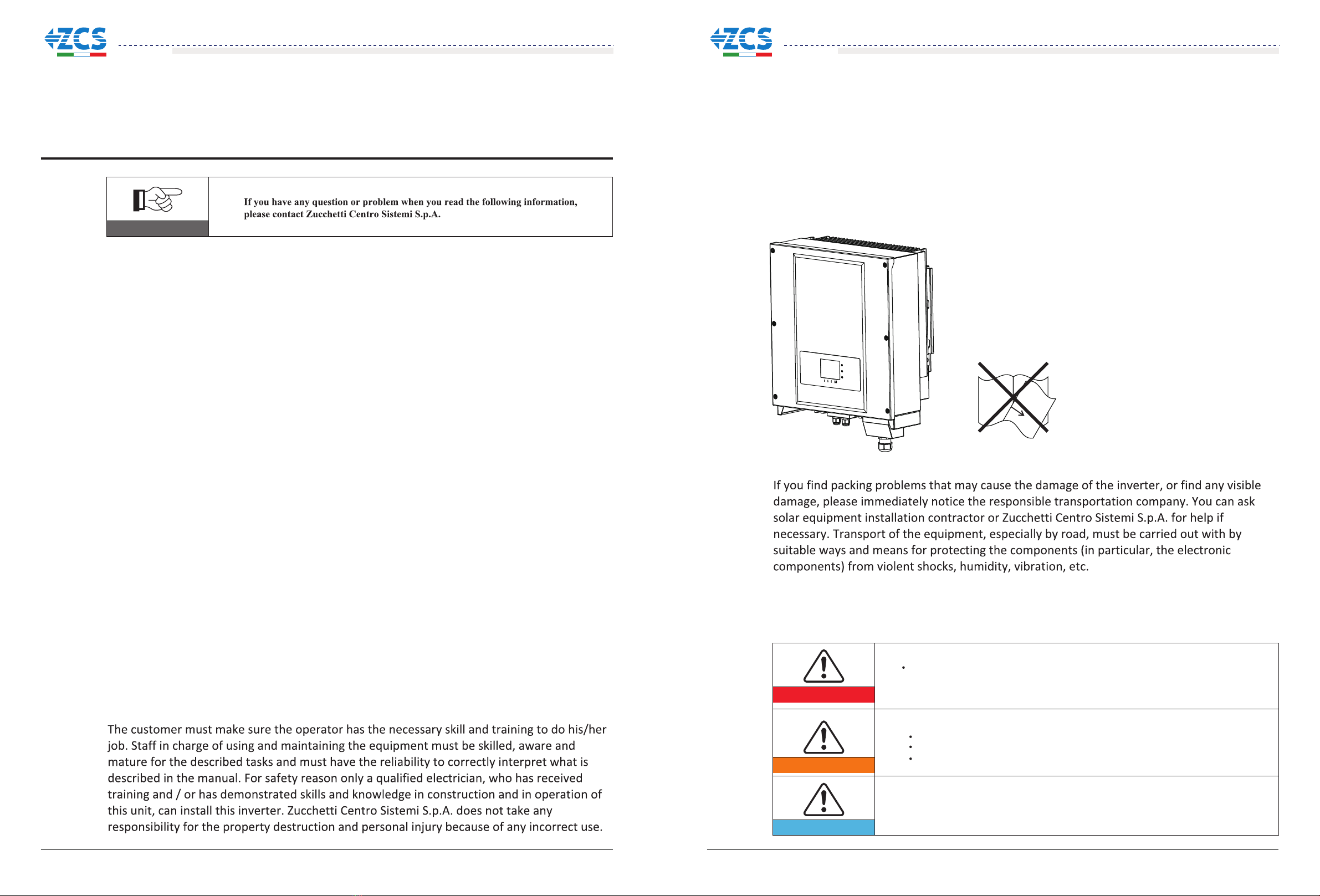
Transport requirements
Electric connection
Please comply with all the current electrical regulations about accident prevention in dealing
with the current inverter.
Before the electrical connection, make sure to use opaque material to cover the
PV modules or to disconnect PV array DC switch. Exposure to the sun, PV array
will produce a dangerous voltage!
Danger
Warning
Attention
All installation accomplished only by professional electrical engineer!
Only get permission by the local power department and complete all electrical
connection by professional electrical engineer then connect inverter into grid!
must be trained;
Completely read the manual operation and understand relevant matters.
Electrical installation and maintenance shall be conducted by qualified
electrician and shall comply with national wiring rules.
1 2
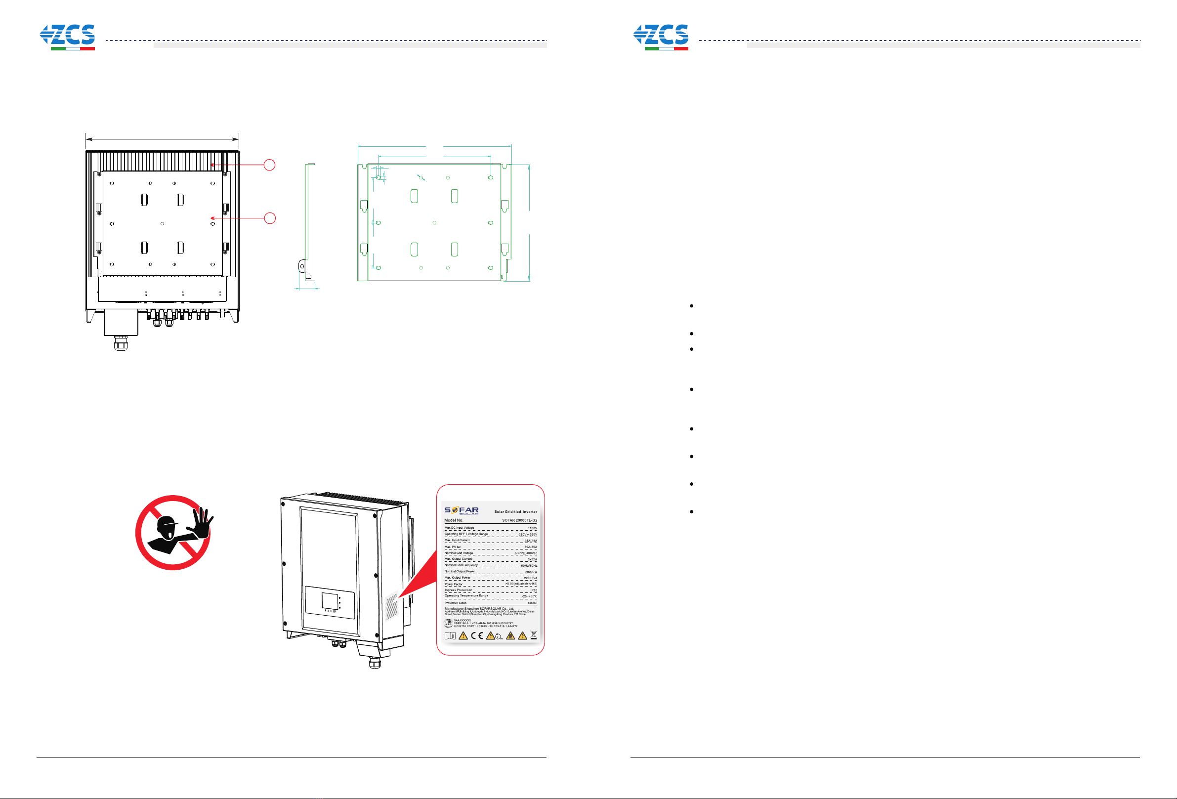
Body sign and protection
There are warring signs on the body of 20~33KTL-G2 ,which has important safety operation
information, it is forbidden to damage these signs.
There is nameplate on side body of 20~33KTL-G2, which has important information of
product parameters, it is forbidden to damage these signs.
Please read the safety notice in this manual carefully, if not it may cause serious
injure or death.
,
20~33KTL-G2
User manual
20~33KTL-G2
User manual

Danger
Attention
Touching the power grid or the terminal of equipment may lead to die of electric
shock or fire!
Don’t touch the terminal or conductor which connect to the power circuit;
Pay attention to anything about grid connection and security document.
Signs on the inverter
There are some symbols which are related to security on the inverter. Please read and
understand the content of the symbols, and then start the installation.
IP65
Operation
Maintenance and repair
EMC / noise level of inverter
Danger
Attention
Disconnected with the PV components array and electricity grid before any
repair work;
After turn off AC breaker and DC switch for 5 minutes later, the maintenance
or repair of the inverter can be carried out!
Some internal components will be very hot when inverter is working. Please wear
protective gloves!
Electromagnetic compatibility (EMC) refers to that one electrical equipment functions in a
given electromagnetic environment without any trouble or error, and impose no
unacceptable effect upon the environment. Therefore, EMC represents the quality characters
of electrical equipment.
The inherent noise-immune character: immunity to internal electrical noise.
External noise immunity: immunity to electromagnetic noise in external system.
Noise emission level: influence of electromagnetic emission upon environment.
Danger
Electromagnetic radiation from inverter may be harmful to health!
Please keep away from the inverter more than 20 cm when inverter is working.
1.2 Symbols and signs
There is residual voltage in the inverter! Before open the equipment,
operator should wait for five minutes to ensure the capacitance discharge
completely.
Be careful of high voltage.
Be careful of high temperature.
Conformity with CE.
Point of connection for grounding.
This indicates the allowed temperature range.
This indicates the degree of protection of the equipment according to
IEC standard 70-1 (EN 60529 June 1997).
Positive pole and negative pole of the input voltage (DC).
3 4
20~33KTL-G2
User manual
20~33KTL-G2
User manual

Transformer
L1
L2
L3
PE
IT
Product characteristics
2
2.1 Product identification
20~33KTL-G2
coming from a photovoltaic generator (PV) into an alternating electric current (AC) Suitable
for being fed into the national grid.
is a multi-string inverter designed to: transform a direct electric current (DC)
The inverter can only be used with photovoltaic modules for on-grid PV power generation. It
can not be used as other or extra purposes, Device manufacture or supplier does not have
responsibility to any loss caused by other purpose usage. And customer should take
responsibility to risk and loss of other purpose usage.Customer should follow this manual for
PV on-grid power generation usage. The input of inverter can only be PV panel ,if user usess
DC source or battery to test the inverer ,it may cause device damage , product damage or
human injure, device manufacture/supplier does not have responsibility for these.
20~33KTL-G2
configurations.For the TT type of electricity grid,the voltage between neutral and earth
should be less than 30V.
inverters are compatible with TN-S、TN-C、TN-C-S、TT、IT grid
Components of the inverter:
Intended grid types:
Outlines of this chapter
Product identification
It introduces the field of use, and how to indentify different types of 20~33KTL-G2.
Function description
It introduces how the inverter works and the function modules inside.
Protection modules
It introduce the protection modules in the inverter.
Field of use
Figure2-1 PV Grid-tied System
Figure2-2 Overview of the grid configurations
Figure2-3 Two parts of the inverter
1 power converter part
5 6
20~33KTL-G2 20~33KTL-G2
Transformer
L1
L2
L3
N
PE
PE
Transformer
L1
L2
L3
PEN
PE
Transformer
L1
L2
L3
N
PE
PE
Transformer
L1
L2
L3
N
PE
TN-S TN-C TN-C-S TT
1
666 mm
512 mm
20~33KTL-G2 20~33KTL-G2
20~33KTL-G2
Efficiency and derate curve It introduces efficiency curve and input/output derating curve.
20~33KTL-G2
User manual
20~33KTL-G2
User manual

The specific models of multi-string inverter that this manual is about are divided into four
groups according to the maximum output power ( 20000TL-G2, 25000TL-G2, 30000TL-G2,
33000TL-G2).
7 8
Figure2-4 Components of bottom view(1)
The choice of model of inverter must be made by a qualified technician who knows about
the installation conditions, Designer chooses the proper inverter model according to
installation site ,enviroment and whole system integration.
Inverter type identification:
30000 TL- G2
Overall dimensions: L×W×H=666mm×512mm×254mm。
Isolation: transformerless
Rated output power
Figure2-8 Front view and left view dimensions
1 Cabinet 2. Human Interface board.
254mm
1
2
666 mm
512 mm
7
2
8
35
4
16
P E N T S R
1. Anti-condensation valve
2. DC switch
3. DC positive poles connecters
4. WIFI/GPRS Interference
5. RS485 input cable gland/Dry contact
6. AC cable gland
7. Fan
8. DC Negative poles connecters
20~33KTL-G2
User manual
20~33KTL-G2
User manual

9 10
Identification labels of the equipment:
The labels must NOT be hidden with
objects and extraneous parts (rags,
boxes, equipment, etc.); they must
be cleaned regularly and kept visible
at all times.
1. Heat sink 2. Bracket
Figure2-9 Back view and Bracket dimensions
512.0mm
1
48mm
459mm
336mm
348.3mm
14mm
10mm
10mm
135mm135mm
2
2.2 Function description
DC power generated by PV array is filtered through input board
before entering into Power board. Input board also offer functions such as insulation
impedance detection and input DC voltage / current detection. DC power is converted to AC
power by Power board. AC power is filtered through Output board then AC power is fed into
the grid. Output board also offer functions such as grid voltage / output current detection,
GFCI and output isolation relay. Control board provides the auxiliary power, controls the
operation state of inverter and shows the operation status by Display board. Display board
displays fault code when inverter is in abnormal operation conditions. At the same time,
Control board can trigger the relay so as to protect the internal components.
string detection board and
Operating Principle
Operating Principle
The string detection board detects the input voltage / current, analyses the operating status of each
PV string and alerts the user that a maintenance required if a problem occurs in the PV string;
The DC switch disconnects internal circuits from the DC input to facilitate maintenance;
The input and output electromagnetic interference (EMI) filters filter out the EMI inside the
20~33KTL-G2 to ensure that the 20~33KTL-G2 meets electromagnetic compatibility requirements;
The Input Board detects the insulation impedance of the PV array and ensures the maximum output
power of the PV system by measuring the voltages & currents of PV array and tracking the
maximum power point (MPPT);
The DC-AC conversion circuit converts DC power into AC power and then the AC power is fed
into the electric grid. The AC output power quality meets the requirements of the electric grid;
The output isolation relay isolates the inverter from the electric grid when the grid or the inverter is
faulty.
The LC filter filters out the high-frequency components from the AC output of 20~33KTL-G2 to
ensure that the AC output meets electric grid requirements;
The Communication Board enables the inverter to communicate via RS485, WIFI(optional), user
can access all the operating data via the web browser(PC) and APP(ios & android).
20~33KTL-G2
User manual
20~33KTL-G2
User manual

Figure2-10 Electrical block diagram
11 12
MASTER DSP SLAVE DSP
DC SWITCH
Anti-graft
protection
Anti-graft protection
OVP
DC SPDIII
OVP
DC SPDIII
IN1A(-)
IN1B(-)
IN1C(-)
MPPT1
DC/DC
INPUT EMI FILTER
MPPT
DC/DC
OUTPUT EMI FILTER
AC SPDIII
EARTH
PE
L1
L2
L3
N
AC Output terminal station
PE
L1
L2
L3
N
L1
L2
L3
N
L1
L2
L3
N1
RLY
EARTH
INVERTER
DC/AC
IN2
IN1
+
-
+
-
+
-
+
+
-
-
+
-
+
-
IN1
IN2
IN1A(+)
IN1B(+)
IN1C(+)
IN1A(-)
IN1B(-)
IN1C(-)
IN2A(+)
IN2B(+)
IN2C(+)
IN2A(-)
IN2B(-)
IN2C(-)
IN1(+)
IN1(-)
IN2(-)
IN2(+)
IN1(+)
IN1(-)
IN2(-)
IN2(+)
DC CABLE GLAND
PV CONNECTOR
DC Input terminal station
IN1(+)
IN1(-)
IN1(-)
IN2(+)
IN1(+)
IN1(-)
IN1(-)
IN2(+)
SD Card
RS485
WIFI
(OPT)
RS485
MARK
MARK
MARK
Upper part of the case
Lower part of the case
OPTIONAL
Machine typesS0/S1/S2/S3/S4/S5
REMOTE CONTROL
ALARM
+T/R
-T/R
GND
GND
+R
N.C
N.O
C
IN1A(+)
IN1B(+)
IN1C(+)
IN2A(+)
IN2B(+)
IN2C(+)
IN2A(-)
IN2B(-)
IN2C(-)
A. Configurable relay
B.1 Remote switching on/off
Function module
The inverter has a configurable switching relay that can be used in various operating
conditions set in the dedicated menu. A typical application example is the closing of the
contact when an alarm occurs.
B. Energy management unit
This control can be used to switch the inverter on/off through an external (remote) control.
B.2 Feeding reactive power into the grid
The inverter is able to produce reactive power and can therefore feed it into the grid through the setting of the
phase shift factor. Feed-in management can be controlled directly by the grid company through a dedicated
RS485 serial interface.
B.3 Limiting the active power fed into the grid
The inverter, if enabled can limit the amount of active power fed into the grid by the inverter to the desired value
(expressed as a percentage).
B.4 Self power reduction when grid over frequency
When the grid frequency is over limited value, inverter will reduce output power which do good to the grid
stability.
B.5 Power reduction due to environmental conditions, input output voltage
The power reduction value and the inverter temperature at which it occurs depend on the ambient temperature
and on many operating para-meters. Example: input voltage, grid voltage and power available from the
photovoltaic field. The inverter can therefore reduce the power during certain periods of the day and according to
the value of these parameters.
The inverter may be monitored remotely through an advanced communications system based on an RS485 serial
interface, or remotely via the WIFI.
C. Data transmission
SD card is used for updating the firmware.
D. Software update
E. Monitoring string inputs
The inverter can monitor and display the voltage and current of each individual string input. It also checks the
status of the strings and generates a warning in the event of a fault.
20~33KTL-G2
User manual
20~33KTL-G2
User manual

C. Grid monitoring
Continuous monitoring of the grid voltage to ensure the voltage and frequency values stay within operating
limits.
D. Inverter internal device protection
The inverter has all kinds of internal protection to protect the device inside when grid or input DC side have
abnormal situation.
E. Ground fault protection
This inverter must be used with panels connected with “floating” connections, that is, with positive and negative
terminals without ground connections,or it may damage the inverter. An advanced ground fault protection
circuit continuously monitors the ground connection and disconnects the inverter when a ground fault is detected.
The ground fault condition is indicated by a red LED on the front panel.
2.4 Efficiency and derating curve
Efficiency curve
Input voltage derating curve
13 14
2.3 Protection modules
A. Anti-islanding
In the event of a local grid outage by the electricity company, or when the equipment is switched off for
maintenance operations, the inverter must be physically disconnected safely, to ensure protection of people
working on the grid, all in accordance with the relevant national standards and laws. To prevent possible
islanding, the inverter is equipped with an automatic protective disconnection system called “Anti-Islanding”.
B. RCMU
Inverters are equipped with a redundancy current device to monitor ground leakage current sensitive to all
components of both direct and alternating current. When the steady-state leakage current is larger than 300mA or
instant leakage current is higher than 30mA/60mA /150mA, inverter will disconnect the grid in different time
delay.
Output voltage derating curve
Vpv=450V
Vpv=600V
Vpv=800V
5% 10% 20% 30% 40% 50% 60% 75% 80% 90% 100%
% of Rated Output Power
86
88
90
92
94
96
98
100
Efficiency[%]
250 350 440 500 600 700 850 900 950
0
10000
15000
20000
25000
30000
35000
40000
Output Power vs Input Voltage
Output Power(W)
Vin(V)
Output Power vs Grid Voltage
4000
8000
12000
16000
20000
24000
40000
28000
32000
36000
180 190 200 210 220
Output Power(W)
0230 240
Vgrid(V)
250 270 280260 320300
290 310
20~33KTL-G2 outputs 230V AC/50Hz
20~33KTL-G2
User manual
20~33KTL-G2
User manual

After unpacking the , check whether deliverables are intact and complete. If any
damage is found or any component is missed, contact the dealer.
Check the list in the table 3-1.
inverter
Installation
3
3.1 Installation Process
Figure3-1 Installation flowchart
Start
Outlines of this chapter
This topic describes how to install the 20~33KTL-G2.
Installation notes
Caution
Danger
Attention
Do not install the inverter on flammable building materials.
Do not store the inverter in areas with flammable or explosive materials.
Do not install the inverter in places prone to body contact because the inverter
shelf and heat sinks become hot during the inverter operation.
Take the inverter weight into consideration when transporting and moving
the inverter.
Install the inverter in an appropriate position and surface.
Assign at least two persons to install the inverter.
This topic describes the process for installing the 20~33KTL-G2.
3.2 Checking Before Installation
Before unpacking, check that the packing materials are intact. After unpacking, check that the
deliverables are complete and intact.
3.3 Tools
Prepare tools required for installation and electrical connections.
3.4 Determining the Installation Position
Determine an appropriate position for installing inverter.
3.5 Moving the inverter
This topic describes how to move inverter to the installation position horizontally.
3.6 Installing the inverter
Before installing inverter, secure the shipped rear panel to the wall. Then secure inverter to
the rear panel by using hexagon screws.
Check before
installation
Prepare installation
tools
Determine the
installation position
Moving the inverter
Installation the rear
panel
Installation the
inverter
End
3.2 Checking Before Installation
Checking Outer Packing Materials
Checking Deliverables
Packing materials and components may be damaged during transportation. Therefore, check
the outer packing materials before installing the inverter. Checking the surface of packing
materials for damage, such as holes and cracks. If any damage is found, do not unpack the
inverter and contact the dealer as soon as possible. You are advised to remove the packing
materials within 24 hours before installing the inverter.
15 16
20~33KTL-G2
User manual
20~33KTL-G2
User manual

No.
1
Pictures
2
3
4
5
6
7
8
9
10
11
1PCS
1PCS
20~33KTL-G2
Rear panel
DC+ input terminal
DC- input terminal
Metal terminals secured to DC+ input
power cables
M6 Hexagon screws
M8*80 Expansion bolts used to secure the
rear panel to the wall
Manual
The warranty card
Certificate
Prepare tools required for installation and electrical connections.
Table3-1 shows the components and mechanical parts that should be delivered
Quantity Description
2PCS
6PCS
1PCS
1PCS
1PCS
Metal terminals secured to DC- input
power cables
3.3 Tools
Table3-1 Shows the components and mechanical parts that should be delivered
Tool Function
Hammer drill
Adjustable wrench
Flat-head screwdriver
Socket wrench
Rubber mallet
Removal tool
Diagonal pliers
Wire stripper
With a drill bit of Φ8.0
Model
Used to drill holes on the wall
Used to tighten expansion bolts
Used to tighten or loosen screws when
installing AC power cables.
Fix rear panel and ground bolts
Used to hammer expansion bolts into
holes
Used to remove DC connectors from the
20~33KTL-G2.
Used to remove AC connectors from
the 20~33KTL-G2.
Note: The torque screwdriver and flat-head
screwdriver are alternative.
Used to cut and tighten cable ties
Used to peel cable jackets
With an open end of larger
than or greater than 32 mm
N/A
M6
N/A
N/A
N/A
N/A
17 18
R 45 crimping tool
JUsed to prepare RJ45 connectors for
Communications cables
N/A
20KTL-G2 4PCS
25KTL-G2 6PCS
30KTL-G2 6PCS
33KTL-G2 6PCS
20KTL-G2 4PCS
25KTL-G2 6PCS
30KTL-G2 6PCS
33KTL-G2 6PCS
20KTL-G2 4PCS
25KTL-G2 6PCS
30KTL-G2 6PCS
33KTL-G2 6PCS
20KTL-G2 4PCS
25KTL-G2 6PCS
30KTL-G2 6PCS
33KTL-G2 6PCS
5mm
20~33KTL-G2
User manual
20~33KTL-G2
User manual

max 15º
80
cm
50 cm 50 cm
50
cm
OK OK NO OK
OK OK NO
NO
NO
OK NO
NO NO
Measuring tape
Minimum installation distance for single 20~33KTL-G2
Determine an appropriate position for installing the 20~33KTL-G2.
Comply with the following requirements when determining the installation position:
Tool Model Function
0-180º
Cable cutter
Crimping tools
Vacuum cleaner
Multimeter
Marker
Level
ESD gloves
Safety goggles
Anti-dust respirator
Used to measure distances
Used to mark signs
Used to ensure that the rear panel is
properly installed
Operators wear ESD gloves when
installing equipment.
Punch operator wearing
Used to cut power cables
Used to crimp power cables
Used to clean up dusts after drilling
holes
Used to check grounding
N/A
N/A
N/A
N/A
N/A
N/A
N/A
N/A
N/A
N/A
3.4 Determining the Installation Position
Figure 3-2 Installation position requirements
19 20
R 45
J2PCS
Notice
Installation position has following requirements:
Installation position can not hinder power cutting off.
Installation wall should have enough load bearing capacity
Installation position should avoid child contact
20~33KTL-G2
User manual
20~33KTL-G2
User manual

Figure3-4 Moving the 20~33KTL-G2 (2)
Step 2 Lift the 20~33KTL-G2 from the packing case and move it to the installation position.
End
Step 1 To determine the position for drilling holes, level hole positions, and then mark the
hole position by using a marker, use the hammer dril to dril hole on the wall. Keeping the
hammer perpendicular to the wall, do not shake when drilling, so as not to damage the walls.
If the aperture errors, need to reposition.
Many 20~33KTL-G2 installation
This topic describes how to move the 20~33KTL-G2 to the installation position
horizontally
Step 1 Opening the packing, insert hands into the slots on both sides of the 20~33KTL-G2
and hold the handles, as shown in Figure 3-3 and Figure 3-4. Two persons are required to
move the 20~33KTL-G2.
Figure 3-3 Moving the 20~33KTL-G2 (1)
3.5 Moving the 20~33KTL-G2
Procedure
Attention
To prevent device damag and personal injury, keep balance when moving the
20~33KTL-G2 because the 20~33KTL-G2 is heavy.
Do not put the 20~33KTL-G2 with its wiring terminals contacting the floor
because the power ports and signal ports are not designed to support the weight
of the 20~33KTL-G2. Place the 20~33KTL-G2 horizontally.
When placing the 20~33KTL-G2 on the floor, put foam or paper under the
20~33KTL-G2 to protect its shell.
3.6 Installing the 20~33KTL-G2
Step 2 The expansion screw is vertically inserted into the hole, pay attention to expanding
screw insertion depth (not too shallow).
Step 3 Putting the rear panel on the wall, the rear panel is fixed by the nuts.
Step 1 Step 2 Step 3
21 22
300mm
100mm
1000mm
200mm
20~33KTL-G2
User manual
20~33KTL-G2
User manual

NOTE:
Before performing electrical connections, ensure that the DC switch is OFF.Since the stored
electrical charge remains in a capacitor long after the DC switch is turned OFF. So it’s
necessary to wait for at least 5 minutes for the capacitor to be electrically discharged.
This topic describes the 20~33KTL-G2 electrical connections. Read this part carefully before
connecting cables.
4.1 Electrical connection
This topic describes the electrical connection process.
4.2 Connecting PGND Cables
Connect inverter to the grounding electrode using protection ground (PGND) cables for
grounding purposes.
4.3 Connecting AC Output Power Cables
Connect inverter to the AC power distribution frame (PDF) or electrical grid using AC output
power cables after obtaining approval from local electrical grid operator.
4.4 Connecting Communication Cables
This topic describes the functions of WIFI and RS485 ports and the method of connecting
WIFI and RS485 communication cables.
4.6 Safety check
Before start the inverter, comply with the safety precautions and check AC、DC connections.
4.5 Connecting DC Input Power Cables
Connect inverter to PV arrays using DC input power cables.
Step 4 Putting the inverter hook on the rear panel.
Step 5 Using an M6 screw back and inverter bottom fastening, to ensure safety.
Step 6 Putting the rear panel and inverter to lock together, In order to ensure the safety (the
user can select lock according to the actual situation).
Step 4 Step 5
Step 6
4Electrical Connections
Outlines of this chapter
PV modules generate electric energy before exposed to sunlight and can create
an electrical shock hazard. Therefore, before connecting DC input power cable,
cover PV modules using opaque cloth.
20~33KTL-G2 has 2 MPP trackers, all PV modules connected to the same MPPT
should have similar rated electrical characteristics (including Isc, Voc, Im, Vm,
Pm and temperature coefficients), have the same number of series connected PV
modules and be all in the same orientation (azimuth and tilt angle).
Installation and maintenance of inverter, must be operated by professional
electrical engineer.
Attention
Danger
Note
23 24
20~33KTL-G2
User manual
20~33KTL-G2
User manual

Prerequisites:
The PGND cables are prepared (8 AWG outdoor power cables are recommended for
grounding purposes).
Procedure:
Step 1 Remove the insulation layer with an appropriate length using a wire stripper, as shown
in Figure 4-3.
L2=L1+(2-3)mm
L1
Note:L2 is 2 to 3mm longer than L1
4.1 Electrical connection
Start
4.2 Connecting PGND Cables
Connect inverter to the grounding electrode using protection ground (PGND) cables for
grounding purposes.
Note:
Good grounding for the 20~33KTL-G2 can help resist the impact of the surge voltage and improve the EMI
performance. First connect the PGND cable before connecting the AC power cable, DC power cable, and
communication cable.
For the system with one 20~33KTL-G2, connect the PGND cable to the ground. For the system with multiple
20~33KTL-G2, connect the PGND cables of all 20~33KTL-G2 to the grounding electrode using equipotential
bonding.
If the installation location is near the ground, first connect the PGND cable to the ground before installing the
20~33KTL-G2 on the wall.
Step 2 Insert the exposed core wires into the OT terminal and crimp them by using a crimping
tool, as shown in Figure 4-4.OT terminal is recommended The PE cable is better larger than
6m2.
L3<2mm
L4<1.5mm
Note 1: L3 is the length between the insulation layer of the ground cable and the crimped part.L4 is the distance between the
crimped part and core wires protruding from the crimped part.
Note 2: The cavity formed after crimping the conductor crimp strip shall wrap the core wires completely. The core wires shall
contact the terminal closely.
Step 3 Install the crimped OT terminal, flat washer, and spring washer on the M5 welded
stud, and tighten the nut to a torque of 5 N.m using a socket wrench.
To enhance the anti-corrosion performance of the ground terminals, apply silica gel on them after connecting the
ground cable.
Figure4-1 Shows the flowchart for connecting cables to the 20~33KTL-G2
Connect PGND Cables Connect AC Output power
Cables
End Connect DC Input power
Cables
Connect Communication
Cables
The inverter is transformerless, Requires The positive pole and the negativepole
of the PV array are not grounded, Otherwise it will cause inverter failure, In the
PV power generation system, all non current carrying metal parts(such as:
Bracket, Junction box shell, inverter shell) should be connected to earth.
Attention
Figure4-2 Ground terminal composition
1. OT Terminal 2. M6 Ground Connection terminal
Note:
Figure4-4 Preparing a ground cable (2)
Figure4-3 Preparing a ground cable (1)
25 26
2
20~33KTL-G2
User manual
20~33KTL-G2
User manual

P E NTSR
PE NTSR
55(PE)
12
55(PE)
12
AC side installation procedure
20~33KTL-G2 is a three-phase output inverter, strictly comply with local grid-connection
requirements and safety standards.
Step 1 Open the AC connector cover.
Figure4-5 Open the cover schematic diagram
Step 2 Remove the insulation layer of an appropriate length according to figure 4-6, then
insert the AC output cable though the PG waterproof cable gland.
Figure4-6 AC Output Cable schematic diagram
Context
All the AC output cables used for the inverters are outdoor five-core cables. To facilitate the
installation, use flexible cables . Table 4-1 lists the recommended specifications for the cables
and the breakers.
4.3 Connecting AC Output Power Cables
Connect the 20~33KTL-G2 to the AC power distribution frame (PDF) or electrical grid using AC
output power cables.
The impedance of grid-tied should be less than 0.85ohm. To
insure reliable anti-islanding function,user should choose PV
specified cable to make sure the power loss less than 1% of rated
power.The grid-tied point should be less than 150m. Check the
table 4-2 for AC cable specification and maximum length for each
model.
Multi core copper wire mm²≥10
Multi core copper wire
Caution
It is not allowed for several inverters to use the same circuit breaker.
It is not allowed to connect loads between inverter and circuit breaker.
Table4-1
Note: For the sake of safety, please make sure to use correctly sized cables, otherwise the current makes the cable overheat or
overload, even cause a fire.
The leakage current of micro breaker should be 100mA≤ Ifn≤300mA,0.1S.
Step 3 Connecting the AC output power cable: The AC output cable(R,S,T,N and PE) is
connected to the terminal block, as shown in figure 4-7.
Figure4-7 Cable connection schematic diagram
Table4-2
27 28
Cable(Copper)
Breaker
20000TL-G2
10mm²
≥
40A
10mm²
≥12mm²
≥
50A 63A
Type
30
49
27 27
44 44
10
13
The cable
cross-sectional
area(mm²)
The maximum length(m)
12mm²
≥
63A
23
38
25000TL-G2 30000TL-G2 33000TL-G2
20000TL-G2 25000TL-G2 30000TL-G2 33000TL-G2
20~33KTL-G2
User manual
20~33KTL-G2
User manual

1. WIFI/GPRS Interface RS485 port2.
12
Zoom in communication port
P E N T S R
Step 4 Crystal plug with RJ45 crimping tool.
Step 5 Insert the plug into the RS485 port on the 20~33KTL-G2.
Step 6 Insert sealing plug into housing, and tighten the screw nut.
Connecting Communications Port
20~33KTL-G2 inverter has 3 communication ports: 2 RS485 ports, 1 WiFi/GPRS port, as shown
below
By the RS485 communication line, connecting 20~33KTL-G2 to communication equipment
(such as data acquisition, PC terminal).
You are recommended to use 24 AWG outdoor shielded network cables with the internal
resistance less than or equal to 1.5 ohms/10 m and external diameter of 4.5 mm to 7.5 mm
as RS485 communications cables.
A waterproof RJ45 connector has six parts: plug, screw nut, seals, housing, sealing plug and
cable screw nut , as shown as follow.
1 2 3 4 5 6
When routing communications cables, ensure that communications cables are separated from power cables and
away from interference sources to prevent communication interruptions.
Step 1 Remove the insulation layer of an appropriate length from the shielded network cable
using a wire stripper.
Step 2 Open 20~33KTL-G2 lower cover and insert the shielded network cable into the cable
screw nut, seals, screw nut.
Step 3 Connect the stripped network cable to corresponding pins on the plug, as shown as
follow.
18
18
TOP
FRONT
R S485 A -, RS485 differential signal +
ColorNo.
White and orange
1
2
3
4
5
6
7
8
R S485 B-, RS485 differential signal-
NC
NC
Figure 4-8 WiFi/GPRS, RS485 position
Connecting RS485 Communications Cables
Figure 4 9 Waterproof RJ45 connector composition-
1. Plug 2. Screw nut 3. Seals 4. Housing 5. Sealing Plug 6. Cable Screw nut
Procedure
Follow-up Procedure
To remove an RJ45 connector from 20~33KTL-G2, remove the cable screw nut, press the clip
on the RJ45 connector, and then pull out the shielded RJ45 connector.
End
Function
Orange
White and green
Blue
White and blue
Green
White and brown
Brown
Figure 4 11 RS485 Connecting Communications Cables(1)-
Figure 4 12 RS485 Connecting Communications Cables(2)-
Figure 4 13 RS485 Connecting Communications Cables(3)-
29 30
4.4 Connecting Communications Cables
20~33KTL-G2
User manual
20~33KTL-G2
User manual

Monitor the inverter via WiFi/GPRS module.
Procedure:
Step 1 Remove waterproof cover using screwdriver.
This topic describes the functions of the RS485 and WIFI ports.
By RS485 interface, transfer the inverter power output information, alarm information,
operation state to the PC terminal or local data acquisition device , then uploaded to the
server (such as S-WE01S).
WiFi/GPRS communication
Figure 4 13 WIFI Connecting Communications Cables(1)-
Step 2 Connect WiFi/GPRS module.
Figure 4 14 WIFI Connecting Communications Cables(2)-
Step 3 Fix the WiFi/GPRS module using two screws.
Figure 4 15 WIFI Connecting Communications Cables(3)-
Communications Port Description
31 32
Note: Follow the WiFi/GPRS manual to start monitoring your inverter.
1. USB-RS485 2. S-WE01S
S
R 485
USB
RS-485
Set the match resistor by the SWT2, the corresponding list as follows (0 OFF, 1 ON).
0
1
Reserve
SWT2_1 SWT2_2 State
Reserve
No connect
Connect
20~33KTL-G2
User manual
20~33KTL-G2
User manual

If only one 20~33KTL-G2 is used, use a communication cable with waterproof RJ45
connectors, and choose either of the two RS485 ports.
WIFI
By the WIFI interface, transfer the inverter power output information, alarm information,
operation state to the PC terminal or local data acquisition device , then uploaded to the
server (such as S-WE01S).
Register remote monitoring of 20~33KTL-G2 at its relevant website or APP according to
monitoring device SN.
The length of the RS485 communication cable should be less than 1000 m.
The length of the Wifi communication cable should be less than 100 m.
If multiple 20~33KTL-G2 are connected to the monitoring device over an RS485/RS232 converter, a
maximum of 31 inverter can be connected in a daisy chain.
If multiple 20~33KTL-G2 are connected to a S-WE01S, a maximum of 31 20~33KTL-G2 can be connected
in three daisy chains.
The 20~33KTL-G2 has a multifunctional relay , its output can be configured. The connecting
terminal in a communication board, as shown in Figure4-8. Connecting CNT10 view as shown
as follow.
It can be connected to the normally open mode (i.e. connecting NO contact and COM
contact),can also be configured as a normally closed mode (i.e. connecting NC contact and
COM contact).
The Relay has 4 different control function, the details please see the LCD display interface
settings on the set relay function description.
CNT10
NC COM NO
No:normally open contact
COM:common contact
Nc:normally closed contact
Note
Figure 4 16 A single 20~33KTL-G2 connecting Communications-
Figure 4 18 Multi 20~33KTL-G2 connecting Communications-
Figure 4 19 Connect multiple Wifi to wireless router-
Connecting Relay Cables
33 34
If multiple 20~33KTL-G2 are used, connect all 20~33KTL-G2 in daisy chain mode over the
RS485 communication cable. Set different Modbus address(1~31) for each inverter in LCD
display and set SWT2(match resistance) at the first and last inverter.
Register remote monitoring of 20~33KTL-G2 at its relevant website or APP according to
monitoring device SN.
RS485/422
Power adapter port
RS485/422 USB/485 port
RS485/422
Power adapter port
RS485/422
USB/485 port
20~33KTL-G2
User manual
20~33KTL-G2
User manual
This manual suits for next models
3
Table of contents
Other ZCS Inverter manuals

ZCS
ZCS 3K-6K TLM LITE Series User manual

ZCS
ZCS AZZURRO Series User manual

ZCS
ZCS Azzurro 3PH HYD5000 ZSS User manual

ZCS
ZCS Azzurro 3000SP User manual

ZCS
ZCS Azzurro 3PH 20000TL-V2 User manual

ZCS
ZCS 1PH 1100TL User manual

ZCS
ZCS AZZYRRO 3-6-ZSS-HP User manual

ZCS
ZCS Azzurro HYD3000-ZP1 User manual

ZCS
ZCS Azzurro HYD 3000 ES User manual

ZCS
ZCS AZZURRO HYD3000 User manual