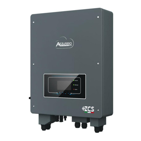
ZCS AZZURRO 1PH HYD3000-ZP1 User manual


Identification: MD-AL-GI-00
Rev. 1.1 of
27/01/2023 - Application:
GID
Pile Reg. IT12110P00002965 - Share Capital € 100,000.00 fully paid up
AR
Company Reg. no. 03225010481 - REA AR no. 94189
ISO 9001 Certified Company
- Certificate no. 9151 - CNS0 - IT-17778
Zucchetti Centro Sistemi S.p.A.
- Green Innovation Division
Via Lungarno, 248
- 52028 Terranuova Bracciolini - Arezzo, Italy
tel. +39 055 91971
- fax. +39 055 9197515
innovation@zcscompany.com
- zcs@pec.it – www.zcsazzurro.com
Hybrid Inverter
1PH HYD3000-HYD6000-ZP1
User Manual

User’s Manual 1PH HYD3000-HYD6000-ZP1
Rev. 1.
0 01/09/2023
Identification: MD-AL-GI-00
Rev. 1.1 of
27/01/2023 - Application: GID
2/193
Table of Contents
1. Introduction......................................................................................................................................................................................... 8
1.1. Product Model Description .................................................................................................................................................. 9
1.2. Product capacity description ............................................................................................................................................11
1.3. Product Appearance .............................................................................................................................................................12
1.3.1. Inverter Port...................................................................................................................................................................13
1.3.2. Battery module port.................................................................................................................................................... 14
2. Requirement for installation and maintenance ..................................................................................................................16
2.1. Safety Notes.............................................................................................................................................................................. 16
2.2. Assembly and maintenance diagram.............................................................................................................................18
2.3. Transportation Requirement............................................................................................................................................ 19
2.4. Electrical Connection............................................................................................................................................................ 20
2.5. Symbols and signs..................................................................................................................................................................21
2.6. Sings on the inverter module:...........................................................................................................................................22
3. Installation..........................................................................................................................................................................................24
3.1. Checking before installation..............................................................................................................................................24
3.2. Contents of the packaging ..................................................................................................................................................24
3.3. Installation environment .................................................................................................................................................... 27
3.4. Installation tools.....................................................................................................................................................................27
3.5. Installation position..............................................................................................................................................................29
3.6. Installation space ...................................................................................................................................................................29
3.7. Product installation............................................................................................................................................................... 30
4. Electrical connections....................................................................................................................................................................34
4.1. Attentions Before Connection...........................................................................................................................................34
4.2. Preparation of Connection Cables...................................................................................................................................35
5. Electrical Connection for the internal system...................................................................................................................... 36
5.1. Internal protection grounding cable connection up to 3 batteries ...................................................................36
5.2. Power cables connection up to 3 batteries .................................................................................................................37
5.3. Internal communication cable connection up to 3 batteries...............................................................................38
5.4. Configuration up to 3 batteries ........................................................................................................................................ 39
5.5. Grounding cable connection for internal protection 4 batteries .......................................................................43
5.6. Connecting power cables 4 batteries............................................................................................................................. 44

User’s Manual 1PH HYD3000-HYD6000-ZP1
Rev. 1.
0 01/09/2023
Identification: MD-AL-GI-00
Rev. 1.1 of
27/01/2023 - Application: GID
3/193
5.7. Internal communication cable connection 4 batteries...........................................................................................45
5.8. Configuration 4 batteries.................................................................................................................................................... 46
5.9. Data collector connection................................................................................................................................................... 50
6. External electrical connection.................................................................................................................................................... 51
6.1. External ground connection of the PGND cable ........................................................................................................51
6.2. Grid connection.......................................................................................................................................................................52
6.3. Connecting a Critical Load (EPS function)...................................................................................................................56
6.4. Photovoltaic connection......................................................................................................................................................59
6.5. COM-Multi function communication connection......................................................................................................64
6.6. Link Port .................................................................................................................................................................................... 65
6.7. RS485(Wired monitoring or inverter cascade monitoring)..........................................................................66
6.8. Logic interface......................................................................................................................................................................... 67
6.9. CT..................................................................................................................................................................................................68
6.10. Meter single-phase DDSU ...................................................................................................................................................68
6.11. Meter three-phase DTSU..................................................................................................................................................... 69
6.12. Measurement of exchange via the single-phase DDSU Meter .............................................................................72
6.13. Measuring external production through the DDSU single-phase Meter.........................................................75
6.14. Setting up exchange meter and production DDSU single-phase Meter...........................................................78
6.15. Checking correct reading of the DDSU single-phase Meter..................................................................................79
6.16. Connection of the three-phase DTSU Meter to the exchange ..............................................................................80
6.17. Measurement of photovoltaic production via three-phase meter DTSU........................................................84
6.18. Three-phase DTSU Meter parameter configuration................................................................................................85
6.19. Correct installation verification DTSU three-phase meter ...................................................................................89
6.20. Measurement of exchange through current sensor.................................................................................................91
6.21. Install the cover ...................................................................................................................................................................... 94
7.Buttons and indicator lights........................................................................................................................................................ 95
7.1. Buttons:...................................................................................................................................................................................... 95
7.2. System status indicator ....................................................................................................................................................... 95
7.3. Battery capacity indicator.................................................................................................................................................. 96
8. Parallel system.................................................................................................................................................................................. 97
9. System Electrical Topology ......................................................................................................................................................... 98
10. Operation ............................................................................................................................................................................................99
10.1. Preliminary checks................................................................................................................................................................ 99
10.2. First start-up of the inverter .............................................................................................................................................99
10.3. Commissioning..................................................................................................................................................................... 103

User’s Manual 1PH HYD3000-HYD6000-ZP1
Rev. 1.
0 01/09/2023
Identification: MD-AL-GI-00
Rev. 1.1 of
27/01/2023 - Application: GID
4/193
10.4. Main menu ............................................................................................................................................................................. 104
10.5. Basic settings ........................................................................................................................................................................ 105
10.5.1. Set language........................................................................................................................................................................... 105
10.5.2. Set Time .................................................................................................................................................................................. 105
10.5.3. Safety Parameter................................................................................................................................................................. 105
10.5.4. Energy Storage Mode......................................................................................................................................................... 105
10.5.5. Photovoltaic Input Mode.................................................................................................................................................. 108
10.5.6. EPS Mode................................................................................................................................................................................ 108
10.5.7. Communication address .................................................................................................................................................. 109
10.5.8. Self-test.................................................................................................................................................................................... 109
10.6. Advanced settings............................................................................................................................................................... 112
10.6.1. Battery parameters ............................................................................................................................................................ 112
10.6.2. Battery Quantity .................................................................................................................................................................. 112
10.6.3. Battery Actiovation ............................................................................................................................................................ 113
10.6.4. Anti Reflux.............................................................................................................................................................................. 113
10.6.5. IV Curve Scan ........................................................................................................................................................................ 114
10.6.6. Logical Interface Control.................................................................................................................................................. 114
10.6.7. Factory Reset ........................................................................................................................................................................ 114
10.6.8. Parallel Setting ..................................................................................................................................................................... 115
10.6.9. Bluetooth Reset.................................................................................................................................................................... 115
10.6.10. CT Calibration ............................................................................................................................................................. 115
10.6.11. Set ElectricityMeter.................................................................................................................................................. 115
10.6.12. Off grid ground ........................................................................................................................................................... 116
10.7. Energy statistics .................................................................................................................................................................. 117
10.8. System interface information......................................................................................................................................... 119
10.9. Event list ................................................................................................................................................................................. 121
10.10. Software Update.................................................................................................................................................................. 121
10.11. Verification of proper functioning ............................................................................................................................... 123
11. Technical specifications............................................................................................................................................................. 126
12. Troubleshooting............................................................................................................................................................................ 127
13. Maintenance.................................................................................................................................................................................... 135
13.1. Store and charge the battery module ......................................................................................................................... 135
14. Uninstalling ..................................................................................................................................................................................... 137
14.1. Uninstallation steps ........................................................................................................................................................... 137
14.2. Packaging................................................................................................................................................................................ 137

User’s Manual 1PH HYD3000-HYD6000-ZP1
Rev. 1.
0 01/09/2023
Identification: MD-AL-GI-00
Rev. 1.1 of
27/01/2023 - Application: GID
5/193
14.3. Storage..................................................................................................................................................................................... 137
14.4. Disposal................................................................................................................................................................................... 137
15. Monitoring systems ..................................................................................................................................................................... 138
15.1. External Wi-Fi adapter...................................................................................................................................................... 138
15.1.1. Installation............................................................................................................................................................................. 138
15.1.2. Configuration........................................................................................................................................................................ 140
15.1.3. Verification ............................................................................................................................................................................ 149
15.1.4. Troubleshooting .................................................................................................................................................................. 152
15.2. Ethernet adapter ................................................................................................................................................................. 156
15.2.1. Installation............................................................................................................................................................................. 156
15.2.2. Verification ............................................................................................................................................................................ 158
15.2.3. Troubleshooting .................................................................................................................................................................. 159
15.3. 4G adapter.............................................................................................................................................................................. 161
15.3.1. Installation............................................................................................................................................................................. 161
15.3.2. Verification ............................................................................................................................................................................ 162
15.4. Datalogger.............................................................................................................................................................................. 166
15.4.1. Preliminary notes on how to configure the datalogger....................................................................................... 166
15.4.2. Electrical connections and configuration.................................................................................................................. 168
15.5. ZSM-DATALOG-04 AND ZSM-DATALOG-10 DEVICES......................................................................................... 172
15.5.1. WI-FI CONFIGURATION ................................................................................................................................................... 172
15.5.2. Ethernet configuration...................................................................................................................................................... 172
15.5.3. Checking that the datalogger has been configured correctly ........................................................................... 180
15.6. ZSM-RMS001/M200 and ZSM-RMS001/M1000 Devices................................................................................... 183
15.6.1. Mechanical description and Datalogger interface................................................................................................. 183
15.6.2. Connecting the Datalogger to the inverters............................................................................................................. 184
15.6.3. Internet connection via Ethernet cable...................................................................................................................... 184
15.6.4. Connecting the power supply and battery pack to the Datalogger................................................................ 184
15.6.5. Connecting the LM2-485 PRO cell irradiance and temperature sensor to the datalogger................... 185
15.6.6. Configuring the Datalogger............................................................................................................................................. 186
15.6.7. Configuring the Datalogger on the ZCS Azzurro portal....................................................................................... 188
15.6.8. Network configuration...................................................................................................................................................... 189
15.7. Local monitoring ................................................................................................................................................................. 191
15.7.1. Requirements for installation of local monitoring................................................................................................ 191
15.7.2. Features of local monitoring .......................................................................................................................................... 192
16. Warranty terms and conditions.............................................................................................................................................. 193

User’s Manual 1PH HYD3000-HYD6000-ZP1
Rev. 1.
0 01/09/2023
Identification: MD-AL-GI-00
Rev. 1.1 of
27/01/2023 - Application: GID
6/193
General instructions
This manual contains important safety instructions that must be followed during installation and maintenance
of the equipment.
Please keep these instructions!
This manual must be considered an integral part of the equipment, and must be available at all times to
everyone who interacts with the equipment. The manual must always accompany the equipment, even when
it is transferred to another user or plant.
Copyright statement
Copyright of this manual belongs to Zucchetti Centro Sistemi S.p.A. No part of this manual (including the
software, etc.) may be copied, reproduced or distributed in any form or by any means without the permission
of Zucchetti Centro Sistemi S.p.A. All rights reserved. ZCS reserves the right to final interpretation. This manual
is subject to change based on feedback from users, installers or customers. Please check our website at
http://www.zcsazzurro.com for the latest version.
Technical support
ZCS offers a support and technical consultancy service accessible by sending a request directly from the
website www.zcsazzurro.com
The following toll-free number is available for the Italian territory: 800 72 74 64.

User’s Manual 1PH HYD3000-HYD6000-ZP1
Rev. 1.
0 01/09/2023
Identification: MD-AL-GI-00
Rev. 1.1 of
27/01/2023 - Application: GID
7/193
Preface
General information
Please read this manual carefully before installation, operation or maintenance.
This manual contains important safety instructions that must be followed during installation and maintenance of
the system.
Scope
This manual describes the assembly, installation, electrical connections, commissioning, maintenance and
troubleshooting of the 1PH HYD3000-HYD6000-ZP1 hybrid inverter.
Keep this manual so that it is accessible at all times.
Recipients
This manual is intended for qualified technical personnel (installers, technicians, electricians, technical support
personnel or anyone who is qualified and certified to operate a photovoltaic system), who are responsible for
installing and starting up the inverter in the photovoltaic and storage energy system and for operators of
photovoltaic and storage systems.
Symbols Used
The following types of safety instruction and general information appear in this document as described below:
“Danger”indicates a hazardous situation which, if not avoided, will result in
death or serious injury.
Danger
“Warning”indicates a hazardous situation which, if not avoided, could result in
death or serious injury
Warning
“Caution”indicates a hazardous situation which, if not avoided, could result in
minor or moderate injury
Caution
“Attention”indicates there are potential risks, if fail to prevent, may lead to
equipment cannot normally or property damage.
Attention
“Note”provides additional information and tips that are valuable for the optimal
operation of the product, will help you to solve a problem or save your time.

User’s Manual 1PH HYD3000-HYD6000-ZP1
Rev. 1.
0 01/09/2023
Identification: MD-AL-GI-00
Rev. 1.1 of
27/01/2023 - Application: GID
8/193
Note
1. Introduction
The 1PH HYD3000-HYD6000-ZSP1 hybrid inverter single-phase household energy storage system consists of
inverter module and lithium battery module. It adopts modular design and can be stacked with building blocks.
The battery capacity varies from 5 to 20 kWh (in case of 4 batteries you need to buy the extension kit, code ZZT-
ZBT5K-EXT-KIT). The system can manage the energy of photovoltaic, battery, utility grid and load according to
the actual application, and realize the optimal distribution of system energy. Multiple working modes are available
to meet diverse needs.
In the event of a power failure (or by switching on the inverter in Off-Grid mode), the 1PH HYD3000-HYD6000-
ZP1 inverter can operate in Emergency Power Supply (EPS) mode. The 1PH HYD3000-HYD6000-ZP1 inverter will
use both the energy created by the photovoltaic panels and the energy stored in the battery to supply energy to
the critical load.
The main features are as follows:
•Stack integrated design, convenient installation, simple maintenance;
•Built-in battery pack equalization management unit to improve battery available capacity;
•Photovoltaic maximum input current 16A, applicable to large current and double-sided module;
•Battery side complete electrical isolation, safer system;
•EPS function to ensure the stable operation of critical load;
•Supports a mixture of new and old batteries;
•Supports battery switch off with a button.

User’s Manual 1PH HYD3000-HYD6000-ZP1
Rev. 1.
0 01/09/2023
Identification: MD-AL-GI-00
Rev. 1.1 of
27/01/2023 - Application: GID
9/193
Figure 1 - Diagram of a system on which an 1PH HYD3000-HYD6000-ZP1 hybrid is installed
1.1. Product Model Description
1PH HYD3000-HYD6000-ZP1 series inverter model:
Figure 2 – Inverter model identifiers
Identifiers
Meaning
Specification
①
Product Model
Stacked optical storage all in one machine
②
Power Grade
5K
,
the power grade of inverter is 6kw
Power grade list:3kw/3.6kw/4kw/4.6kw/5kw/6kw
③
Inverter Model
Single-phase hybrid energy storage inverter
Figure 3 – Model identifiers

User’s Manual 1PH HYD3000-HYD6000-ZP1
Rev. 1.
0 01/09/2023
Identification: MD-AL-GI-00
Rev. 1.1 of
27/01/2023 - Application: GID
10/193
Identifiers
Meaning
Specification
①
Product series name
AZZURRO ZCS series battery module name
②
Battery module energy grade
5K: Battery module energy is 5kWh

User’s Manual 1PH HYD3000-HYD6000-ZP1
Rev. 1.
0 01/09/2023
Identification: MD-AL-GI-00
Rev. 1.1 of
27/01/2023 - Application: GID
11/193
1.2. Product capacity description
The 1PH HYD3000-HYD6000-ZP1 series residential energy storage system supports power and capacity
expansion and supports up to six inverter modules in parallel. One inverter module supports up to four batteries
expansion modules. (in case of 4 batteries you need to buy the extension kit, code ZZT-ZBT5K-EXT-KIT).
Figure 4 – Storage capacity descrition

User’s Manual 1PH HYD3000-HYD6000-ZP1
Rev. 1.
0 01/09/2023
Identification: MD-AL-GI-00
Rev. 1.1 of
27/01/2023 - Application: GID
12/193
1.3. Product Appearance
Front Side Back Side
Figure 5 - Product front side and back side
1
Inverter
5
Pedestal
2
Dc switch
6
Inverter Radiator
3
LCD display screen
7
Battery Module Radiator
4
Battery module

User’s Manual 1PH HYD3000-HYD6000-ZP1
Rev. 1.
0 01/09/2023
Identification: MD-AL-GI-00
Rev. 1.1 of
27/01/2023 - Application: GID
13/193
1.3.1.Inverter Port
Right side port Left side port
Figure 6 - Inverter port diagram
1
Grid connection port
6
WIFI/4G port
2
Load connection port
7
Battery black start switch
3
Inverter signal port
8
Battery input switch
4
Dc Switch
9
Battery connection port
5
PV input port
10
Battery signal port
1
2
3
4
5
6
7
8
9
10
0

User’s Manual 1PH HYD3000-HYD6000-ZP1
Rev. 1.
0 01/09/2023
Identification: MD-AL-GI-00
Rev. 1.1 of
27/01/2023 - Application: GID
14/193
1.3.2.Battery module port
Battery left side port Battery right side port
Figure 7 – Battery module port diagram
1
Battery output terminal +
3
Link port in
2
Battery output terminal -
4
Link port out

User’s Manual 1PH HYD3000-HYD6000-ZP1
Rev. 1.
0 01/09/2023
Identification: MD-AL-GI-00
Rev. 1.1 of
27/01/2023 - Application: GID
15/193
Product label
Figure 8 – Battery module port diagram

User’s Manual 1PH HYD3000-HYD6000-ZP1
Rev. 1.
0 01/09/2023
Identification: MD-AL-GI-00
Rev. 1.1 of
27/01/2023 - Application: GID
16/193
2. Requirement for installation and maintenance
Before installation, please read this manual carefully and make sure you fully understand its contents. The 1PH
HYD3000-HYD6000-ZP1 inverter strictly complies with the safety, design and testing regulations provided for by
the national standards.
During installation, operation and maintenance, operators must carefully observe the local safety standards.
Improper use may result in electrical shock and harm and damage to persons, the equipment and its components.
Contact the nearest authorised service centre for any repairs or maintenance. Contact your distributor for
information on the nearest authorised service centre. DO NOT carry out repairs yourself, as this may result in
injury or damage.
Ensure that the operator has the necessary skills and training to operate the equipment. Personnel responsible
for the use and maintenance of the equipment must be qualified and capable of performing the activities
described, and must also have appropriate knowledge on how to correctly interpret the contents of this manual.
For safety reasons, this inverter can only be installed by a qualified electrician with the necessary training and/or
skills and knowledge. Zucchetti Centro Sistemi S.p.A. declines all responsibility for damage to property or personal
injury caused by incorrect use of the device.
Install and start the inverter according to the following instructions. Place the inverter on suitable load-bearing
supports with sufficient load capacity (such as walls or racks) and make sure that the inverter is positioned
vertically. Choose a suitable location for the installation of the electrical equipment. Make sure there is sufficient
space for heat dispersion and to accommodate future maintenance. Maintain adequate ventilation and ensure that
there is enough air circulation for cooling.
If you have problems with the packaging that could damage the inverter or if you find any visible damage,
immediately notify the transport company. If necessary, request assistance from an installer of photovoltaic
systems or from Zucchetti Centro Sistemi SpA. Transport of the equipment, especially by road, must be carried
out with vehicles suitable to protect the components (in particular, electronic components) against violent
knocks, humidity, vibrations, etc.
2.1. Safety Notes
•Electrical installation and maintenance of the system must be carried out by qualified and certified
electricians in compliance with national regulations.
•The 1PH HYD3000-HYD6000-ZP1 inverter may only be installed by qualified PERSONNEL and by those who
have the appropriate certification, as required by the local authorities.
•DO NOT place materials explosives or flammable (e.g. gasoline, kerosene, oil, wood, cotton or similar) near
the batteries or the 1PH HYD3000-HYD6000-ZP1 inverter.
•Before maintenance, disconnect the AC connection, then the batteries and the photovoltaic system
(PV1&PV2), wait at least 5 minutes (capacitor discharge time) so as to prevent electric shock.
•The 1PH HYD3000-HYD6000-ZP1 inverter must be completely disconnected (BAT, PV & AC) during
maintenance.

User’s Manual 1PH HYD3000-HYD6000-ZP1
Rev. 1.
0 01/09/2023
Identification: MD-AL-GI-00
Rev. 1.1 of
27/01/2023 - Application: GID
17/193
•The 1PH HYD3000-HYD6000-ZP1 inverter may reach high temperatures and have rotating parts inside
during operation. Switch off the 1PH HYD3000-HYD6000-ZP1 inverter and wait for it to cool down before
performing any maintenance.
•Keep children away from the batteries and from the 1PH HYD3000-HYD6000-ZP1 inverter.
•Do not open the front cover of the 1PH HYD3000-HYD6000-ZP1 inverter. Opening the front cover will void
the product warranty.
•Damage caused by improper installation/operation is NOT covered by the product warranty.

User’s Manual 1PH HYD3000-HYD6000-ZP1
Rev. 1.
0 01/09/2023
Identification: MD-AL-GI-00
Rev. 1.1 of
27/01/2023 - Application: GID
18/193
2.2. Assembly and maintenance diagram
•The battery must be protected against short circuits during transport and installation.
•The inverter 1PH HYD3000-HYD6000-ZP1/batteries must be located in well-ventilated areas. Do not place
the 1PH HYD3000-HYD6000-ZP1 inverter/batteries in a cabinet or in an airtight or poorly ventilated
location. This could be extremely hazardous to the performance and life of the system.
•Keep the 1PH HYD3000-HYD6000-ZP1 inverter and batteries away from direct sunlight. Do not bring the
1PH HYD3000-HYD6000-ZP1 inverter and batteries near ovens, flames or other heat sources as the battery
may catch fire and cause an explosion.
•Use a multimeter to check the battery polarity and voltage before turning on the power. Make sure that the
connections are made according to the instructions in this manual.
•Use the multimeter to check the PV voltage and polarity before closing the PV switch. Make sure that the
connections are made according to the instructions in this manual.
•If you want to store the batteries without using them, disconnect them from the 1PH HYD3000-HYD6000-
ZP1 inverter and store them in a cool, dry and well-ventilated area.
•Battery maintenance workers must have the skills and knowledge required to carry out this activity.
•The 1PH HYD3000-HYD6000-ZP1 inverter does not have an isolation transformer so the positive and
negative polarities of the PV string do NOT have to be grounded, otherwise the inverter may be damaged.
All non-current-carrying metal parts (such as the PV module frame, PV rack, housing of the combiner box,
and housing of the inverter) in the photovoltaic power system must be connected to the ground.
•Attention: Do not disassemble or break the battery. The electrolytes in the battery may be toxic and cause
damage to skin and eyes.
•Attention: during installation and maintenance of the product, please follow the rules below.
a) Remove watches, rings and other metal objects.
b) Only use tools with insulated handles.
c) Wear rubber gloves and shoes.
d) Do not place tools or metal objects on top of the battery.
e) Turn off the 1PH HYD3000-HYD6000-ZP1 inverter and batteries before connecting/disconnecting
the battery terminals.
f) Both the positive and negative polarities must be isolated from the ground.
•Please install the product according to the following section. Place inverter in an appropriate bearing
capacity objects (such as solid brick wall, or strength equivalent mounting surface, etc.) and make sure
inverter vertical placed. A proper installation location must have enough space for fire engine access in
order for maintenance if faulty occur. Ensure the inverter is installed in a wall ventilated environment and
have enough air cooling cycle. Air humidity should less than 90%.

User’s Manual 1PH HYD3000-HYD6000-ZP1
Rev. 1.
0 01/09/2023
Identification: MD-AL-GI-00
Rev. 1.1 of
27/01/2023 - Application: GID
19/193
2.3. Transportation Requirement
Inverter is in the good electrical and physical condition when it ship out from factory. During transport, inverter
must be placed in its original package or other proper package. Transportation company should responsible for
any damage during transport period.
If you find any packing problems that may cause the damage of inverter or any visible damage, please notice the
responsible transportation company immediately. You can ask your installer or Zucchetti Centro Sistemi S.p.a. for
help is necessary.
•This product contains battery module through UN38.3, belongs to the ninth category of dangerous goods.
Therefore, loading and unloading must comply with local laws and regulations and industry standards
during transportation. Rough loading and unloading may cause short circuit or damage to batteries in
containers, which may result in battery leakage, breakage, explosion, or fire. Shipping complies with the
IMDG CODE and the International Maritime Dangerous Goods CODE.
•For land transportation, comply with ADR or JT T617 shipping requirements
•Meet the regulatory requirements of the transport regulatory authorities of the country of origin, route and
destination.
Comply with international regulations for the transport of dangerous goods and the supervision requirements of
the corresponding national transport regulatory authorities.
This manual suits for next models
7
Table of contents
Other ZCS Inverter manuals

ZCS
ZCS TL Series User manual

ZCS
ZCS Azzurro 3PH HYD5000 ZSS User manual

ZCS
ZCS 3K-6K TLM LITE Series User manual

ZCS
ZCS Azzurro 3PH 20000TL-V2 User manual

ZCS
ZCS HYD 3000-ES User manual

ZCS
ZCS HYDxxxxES Series User manual

ZCS
ZCS Azzurro HYD 3000 ES User manual

ZCS
ZCS AZZURRO Series User manual

ZCS
ZCS 20000TL-G2 User manual

ZCS
ZCS Azzurro 3000SP User manual