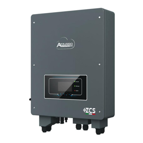
ZCS Azzurro 3PH 20000TL-V2 User manual


Identification: MD-AL-GI-00
Rev. 1.1 of 15/03/2021 - Application:
GID
Zucchetti Centro Sistemi S.p.A. - Green Innovation Division
Via Lungarno, 248 - 52028 Terranuova Bracciolini - Arezzo, Italy
tel. +39 055 91971 - fax. +39 055 9197515
innovation@zcscompany.com - zcs@pec.it –www.zcsazzurro.com
Reg. Pile IT12110P00002965 - Share Capital € 100,000.00 fully paid up
AR Company Reg. no. 03225010481 - REA AR no. 94189
ISO 9001 Certified Company - Certificate no. 9151 - CNS0 - IT-17778
Grid-connected inverter
3PH 20000TL-33000TL-V2
User Manual

2 / 136
Identification: MD-AL-GI-00
Rev. 1.1 of 15/03/2021 - Application: GID
User’s Manual 3PH 20000TL - 33000TL-V2
Rev. 1.1 15/03/2021
Table of Contents
1. Preliminary safety instructions ..............................................................................................................................................................8
1.1. Safety instructions ....................................................................................................................................................................8
1.2. Symbols and icons..................................................................................................................................................................11
2. Product features.........................................................................................................................................................................................13
2.1. Product presentation............................................................................................................................................................13
2.2. Description of functions ......................................................................................................................................................17
2.3. Module protection..................................................................................................................................................................20
2.4. Efficiency and derating curves..........................................................................................................................................21
3. Installation....................................................................................................................................................................................................23
3.1. Installation process ...............................................................................................................................................................24
3.2. Checks before installation...................................................................................................................................................24
3.3. Installation tools.....................................................................................................................................................................26
3.4. Installation position ..............................................................................................................................................................28
3.5. Moving the 3PH 20000TL - 33000TL-V2 inverter ...................................................................................................30
3.6. Installing the 3PH 20000TL - 33000TL-V2 inverter...............................................................................................31
4. Electrical connections..............................................................................................................................................................................33
4.1. Electrical connections ..........................................................................................................................................................34
4.2. Connecting PNGD cables (grounding)...........................................................................................................................34
4.3. Connecting the DC input power cables .........................................................................................................................36
4.4. Connecting the AC output power cables.......................................................................................................................42
4.5. Connecting the communication cables .........................................................................................................................45
5. Commissioning the inverter..................................................................................................................................................................48
5.1. Safety inspection before commissioning......................................................................................................................48
5.2. Starting the inverter..............................................................................................................................................................48
6. Operating interface ...................................................................................................................................................................................50
6.1. Operating panel and display..............................................................................................................................................50
6.2. Main interface..........................................................................................................................................................................51

3 / 136
Identification: MD-AL-GI-00
Rev. 1.1 of 15/03/2021 - Application: GID
User’s Manual 3PH 20000TL - 33000TL-V2
Rev. 1.1 15/03/2021
6.3. Main menu.................................................................................................................................................................................54
7. Troubleshooting and maintenance ....................................................................................................................................................71
7.1. Troubleshooting......................................................................................................................................................................71
7.2. Maintenance .............................................................................................................................................................................79
8. Uninstalling ..................................................................................................................................................................................................80
8.1. Uninstallation steps...............................................................................................................................................................80
8.2. Packaging...................................................................................................................................................................................80
8.3. Storage ........................................................................................................................................................................................80
8.4. Disposal ......................................................................................................................................................................................80
9. Technical specifications ..........................................................................................................................................................................82
10. Monitoring system...........................................................................................................................................................................83
10.1. External Wi-Fi adapter.........................................................................................................................................................83
10.1.1. Installation ................................................................................................................................................................................83
10.1.2. Configuration ...........................................................................................................................................................................84
10.1.3. Verification................................................................................................................................................................................93
10.1.4. Troubleshooting......................................................................................................................................................................97
10.2. Ethernet adapter.................................................................................................................................................................. 102
10.2.1. Installation .............................................................................................................................................................................102
10.2.2. Verification............................................................................................................................................................................. 104
10.2.3. Troubleshooting................................................................................................................................................................... 106
10.3. 4G adapter.............................................................................................................................................................................. 107
10.3.1. Installation .............................................................................................................................................................................107
10.3.2. Verification............................................................................................................................................................................. 110
10.4. Datalogger ..............................................................................................................................................................................113
10.4.1. Preliminary notes on how to configure the datalogger ......................................................................................113
10.4.2. Electrical connections and configuration..................................................................................................................114
10.4.3. ZSM-DATALOG-04 AND ZSM-DATALOG-10 DEVICES ..........................................................................................117
10.4.4. WI-FI CONFIGURATION....................................................................................................................................................117
10.4.5. Ethernet configuration......................................................................................................................................................117
10.4.6. Checking that the datalogger has been configured correctly ...........................................................................124
10.4.7. ZSM-RMS001/M200 and ZSM-RMS001/M1000 Devices ..................................................................................127
4 / 136
Identification: MD-AL-GI-00
Rev. 1.1 of 15/03/2021 - Application: GID
User’s Manual 3PH 20000TL - 33000TL-V2
Rev. 1.1 15/03/2021
10.4.7.1. Mechanical description and Datalogger interface....................................................................................... 127
10.4.7.2. Connecting the Datalogger to the inverters....................................................................................................128
10.4.7.3. Internet connection via Ethernet cable............................................................................................................128
10.4.7.4. Connecting the power supply and battery pack to the Datalogger...................................................... 128
10.4.7.5. Connecting the LM2-485 PRO cell irradiance and temperature sensor to the datalogger ........129
10.4.8. Configuring the Datalogger.............................................................................................................................................130
10.4.8.1. Configuring the Datalogger on the ZCS Azzurro portal.............................................................................133
10.4.8.2. Network configuration............................................................................................................................................134
10.4.9. Local monitoring.................................................................................................................................................................. 135
10.4.9.1. Requirements for installation of local monitoring...................................................................................... 135
10.4.9.2. Features of local monitoring.................................................................................................................................135
11. Warranty terms and conditions.............................................................................................................................................. 136

5 / 136
Identification: MD-AL-GI-00
Rev. 1.1 of 15/03/2021 - Application: GID
User’s Manual 3PH 20000TL - 33000TL-V2
Rev. 1.1 15/03/2021
General instructions
This manual contains important safety instructions that must be followed during installation and
maintenance of the equipment.
Please keep these instructions!
This manual must be considered an integral part of the equipment, and must be available at all times to
everyone who interacts with the equipment. The manual must always accompany the equipment, even when
it is transferred to another user or plant.
Copyright statement
Copyright of this manual belongs to Zucchetti Centro Sistemi S.p.A. No part of this manual (including the
software, etc.) may be copied, reproduced or distributed in any form or by any means without the
permission of Zucchetti Centro Sistemi S.p.A. All rights reserved. ZCS reserves the right to final
interpretation. This manual is subject to change based on feedback from users, installers or customers.
Please check our website at http://www.zcsazzurro.com for the latest version.
Technical support
ZCS offers a support and technical consultancy service accessible by sending a request directly from the
website https://www.zcsazzurro.com/it/support.
The following toll-free number is available for the Italian territory: 800 72 74 64.

6 / 136
Identification: MD-AL-GI-00
Rev. 1.1 of 15/03/2021 - Application: GID
User’s Manual 3PH 20000TL - 33000TL-V2
Rev. 1.1 15/03/2021
Preface
General information
Please read this manual carefully before installation, use or maintenance.
This manual contains important safety instructions that must be followed during installation and
maintenance of the system.
Scope
This manual describes the assembly, installation, electrical connections, commissioning, maintenance and
troubleshooting of the following AZZURRO inverters:
3PH 20000TL-V2 / 3PH 25000TL-V2 / 3PH 30000TL-V2 / 3PH 33000TL-V2
Keep this manual so that it is accessible at all times.
Recipients
This manual is intended for qualified technical personnel (installers, technicians, electricians, technical
support personnel or anyone who is qualified and certified to operate a photovoltaic system), who are
responsible for installing and starting the inverter in the photovoltaic system and for operators of the
photovoltaic system.
Symbols used
This manual provides information for safe operation and uses certain symbols to ensure the safety of
personnel and materials, and for efficient use of the equipment during normal operation.
It is important to understand this information to avoid accidents and damage to property. Please take note
of the following symbols used in this manual.
Danger: indicates a hazardous situation which, if not resolved or avoided,
could result in serious personal injury or death.
Danger
Warning: indicates a hazardous situation which, if not resolved or avoided,
could result in serious personal injury or death.
Warning

7 / 136
Identification: MD-AL-GI-00
Rev. 1.1 of 15/03/2021 - Application: GID
User’s Manual 3PH 20000TL - 33000TL-V2
Rev. 1.1 15/03/2021
Caution: indicates a hazardous situation which, if not resolved or avoided,
could result in minor or moderate personal injury.
Caution
Attention: indicates a potentially hazardous situation which, if not resolved or
avoided, could result in damage to the system or other property.
Attention
Note: provides important tips on the correct and optimal operation of the
product.
Note

8 / 136
Identification: MD-AL-GI-00
Rev. 1.1 of 15/03/2021 - Application: GID
User’s Manual 3PH 20000TL - 33000TL-V2
Rev. 1.1 15/03/2021
1. Preliminary safety instructions
If you have problems or questions regarding the reading and
understanding of the following information, please contact Zucchetti
Centro Sistemi S.p.A. through the appropriate channels.
Note
General information in this chapter
Safety instructions
It mainly highlights the safety instructions to be followed during installation and use of the equipment.
Symbols and icons
Introduces the main safety symbols on the inverter.
1.1. Safety instructions
Before installing and using the equipment, make sure you read and understand the instructions in this
manual and familiarise yourself with the relative safety symbols shown in this chapter.
Depending on national and local requirements, permission must be obtained from your local provider before
connecting to the electrical grid, making sure that the connections are carried out by a qualified electrician.
Contact the nearest authorised service centre for any repairs or maintenance. Contact your distributor for
information on the nearest authorised service centre. DO NOT carry out repairs yourself, as this may result
in injury or damage.
Before installing and operating the equipment, the electrical circuit of the strings must be disconnected by
opening the string circuit breaker to interrupt the high-voltage DC of the photovoltaic system. Failure to do
so could result in serious injury.
Qualified personnel
Ensure that the operator has the necessary skills and training to operate the equipment. Personnel
responsible for use and maintenance of the equipment must be qualified and capable of performing the
activities described, and must also have appropriate knowledge on how to correctly interpret the contents
of this manual. For safety reasons, this inverter can only be installed by a qualified electrician with the
necessary training and/or skills and knowledge. Zucchetti Centro Sistemi S.p.A. declines all responsibility for
damage to property or personal injury caused by incorrect use of the device.

9 / 136
Identification: MD-AL-GI-00
Rev. 1.1 of 15/03/2021 - Application: GID
User’s Manual 3PH 20000TL - 33000TL-V2
Rev. 1.1 15/03/2021
Installation requirements
Install and start the inverter according to the following instructions. Place the inverter on suitable load-
bearing supports with sufficient load capacity (such as walls or photovoltaic racks) and make sure that the
inverter is positioned vertically. Choose a suitable location for the installation of the electrical equipment.
Make sure there is sufficient space for heat dispersion and to accommodate future maintenance. Maintain
adequate ventilation and ensure that there is enough air circulation for cooling.
Figure 1 –Do not lose or damage this manual
Transport requirements
If you encounter problems with the packaging, or if you find any visible damage, please notify the transport
company immediately. If necessary, request assistance from an installer of photovoltaic systems or from
Zucchetti Centro Sistemi SpA. Transport of the equipment, especially by road, must be carried out with
vehicles suitable to protect the components (in particular, electronic components) against violent knocks,
humidity, vibrations, etc.
Electrical connections
Please pay attention to the electrical regulations on accident prevention when dealing with photovoltaic
inverters.
Before connecting the mains power, be sure to disconnect the photovoltaic
modules by disconnecting all the DC switches of the generator. When exposed
to the sun, the photovoltaic panels produce a voltage that can be dangerous!
Danger

10 / 136
Identification: MD-AL-GI-00
Rev. 1.1 of 15/03/2021 - Application: GID
User’s Manual 3PH 20000TL - 33000TL-V2
Rev. 1.1 15/03/2021
All installation operations must be carried out by a professional electrician,
who must:
be prepared.
carefully read this manual and understand its contents.
Warning
Before connecting the inverter to the grid, make sure that all the necessary
permits have been obtained from the local grid operator and that all the
electrical connections are made by a professional electrician.
Attention
Do not remove the information label or open the inverter.
Otherwise, ZCS will not provide any warranty or maintenance.
Note
Operation
Contact with the electrical grid or the terminal of the equipment may cause
electrocution or fire!
Do not touch the terminal or the conductor connected to the electrical grid.
Follow all the instructions and safety requirements relating to the mains
connection.
Danger
Some internal components reach very high temperatures when the inverter
is in operation. Wear protective gloves!
Attention

11 / 136
Identification: MD-AL-GI-00
Rev. 1.1 of 15/03/2021 - Application: GID
User’s Manual 3PH 20000TL - 33000TL-V2
Rev. 1.1 15/03/2021
Maintenance and repair
Before carrying out any repairs, disconnect the inverter from the mains
network (AC side) and from the photovoltaic system (DC side).
After switching off the AC and DC switches, wait 5 minutes before carrying
out any repairs or maintenance on the inverter!
Danger
The inverter should start working again after any faults have been fixed. For
any repairs, contact your local authorised service centre;
Do not disassemble the internal components of the inverter without
permission. This will void the warranty. Zucchetti Centro Sistemi S.p.A. shall
not be responsible for any damage or loss caused by these actions.
Attention
1.2. Symbols and icons
Safety signals
Pay attention to possible burns due to hot parts.
Only touch the screen or press the keys while the inverter is in operation.
Caution
The PV strings should be connected to the ground in accordance with the
local regulations!
To ensure the safety of the system and people, the inverter and photovoltaic
strings must be securely connected to the ground.
Attention
Ensure the correct DC input voltage; which must be below the maximum
allowable DC voltage. Overvoltage can cause permanent damage to the
inverter or other faults which are not covered by the warranty!
Warning

12 / 136
Identification: MD-AL-GI-00
Rev. 1.1 of 15/03/2021 - Application: GID
User’s Manual 3PH 20000TL - 33000TL-V2
Rev. 1.1 15/03/2021
Symbols on the inverter
Some safety symbols are located on the inverter. Read and understand the contents of the symbols before
installing the inverter.
Residual voltage may be present on the inverter! Before opening the inverter,
wait 5 minutes to ensure that the capacitors are completely discharged.
Beware of high voltage
Beware of high temperatures
Complies with the European Standards (CE)
Ground connection point
Read this manual before installing the inverter.
Indication of the allowable temperature range
Degree of protection of the equipment according to the IEC 70-1 standard (EN
60529 June 1997).
Positive and negative polarities of the input voltage (DC).
’Smin"“’"
There is residual voltage in the inverter! Before opening the equipment,
wait five minutes to ensure that the capacitance has been completely
discharged.
Be careful of high voltage.
Be careful of high temperature.
Complies with European standards.
Ground connection point.
This indicates the allowed temperature range.
This indicates the degree of protection of the equipment according to
IEC standard 70-1 (EN 60529 June 1997).
Positive and negative polarities of the input voltage (DC).

13 / 136
Identification: MD-AL-GI-00
Rev. 1.1 of 15/03/2021 - Application: GID
User’s Manual 3PH 20000TL - 33000TL-V2
Rev. 1.1 15/03/2021
2. Product features
General information in this chapter
Product description and dimensions
The field of use and overall dimensions of the 3PH 20000TL - 33000TL-V2 inverters are indicated in this
section.
Description of functions
Describes how the 3PH 20000TL - 33000TL-V2 inverters and their internal operating modules work.
Efficiency curve
Describes the efficiency curves of the inverter.
2.1. Product presentation
Field of use
The 3PH 20000TL - 33000TL-V2 inverters are grid-connected photovoltaic inverters equipped with a dual-
channel MPPT, capable of converting the direct current generated by the photovoltaic strings into three-
phase sine wave alternating current and feeding the energy to the public electricity grid. An AC circuit
breaker (see related chapter) must be used as a disconnecting device and must always be easily accessible.
Figure 2 –Grid-connected photovoltaic system
The 3PH 20000TL - 33000TL-V2 inverters can only be used with photovoltaic modules that do not require
one of the polarities to be grounded. The operating current and voltage during normal operation must not
exceed the limits indicated in the technical specifications. Only photovoltaic modules can be connected to

14 / 136
Identification: MD-AL-GI-00
Rev. 1.1 of 15/03/2021 - Application: GID
User’s Manual 3PH 20000TL - 33000TL-V2
Rev. 1.1 15/03/2021
the input of the inverter (do not connect batteries or other power supply sources). A disconnecting switch
must be installed between the inverter and the grid, which must be sized for a maximum current of 63 A.
Intended networks
The 3PH 20000TL - 33000TL-V2 TL inverters are compatible with network configurations TN-S, TN-C, TN-
C-S, TT, IT. For the type of TT electrical grid, the voltage between neutral and ground must be less than 30V.
The figure below shows the diagrams of the grids just described.
Figure 3 –Wiring diagrams of grid types on which the 3PH 20000TL - 33000TL-V2 inverter can be installed
Inverter components
Inverter models of the 3PH 20000TL - 33000TL-V2 family are divided into four sizes according to
their maximum output power (20 kW, 25 kW, 30 kW, 33 kW).

15 / 136
Identification: MD-AL-GI-00
Rev. 1.1 of 15/03/2021 - Application: GID
User’s Manual 3PH 20000TL - 33000TL-V2
Rev. 1.1 15/03/2021
Figure 4 –Bottom view of the inverter
1. Anti-condensation valve
2. DC switch
3. DC positive pole connectors
4. Wi-Fi connector
5. RS485 cable entry
6. AC cable entry
7. Cooling fans
8. DC negative pole connectors
• The inverter model must be chosen by a qualified technician who knows the installation conditions, the
devices that will be installed outdoors and the possible integration with existing systems.
• Optional components of the inverter should be chosen by a qualified technician who is familiar with the
installation conditions.
• Overall dimensions: H x W x D = 666 mm x 512 mm x 254 mm

16 / 136
Identification: MD-AL-GI-00
Rev. 1.1 of 15/03/2021 - Application: GID
User’s Manual 3PH 20000TL - 33000TL-V2
Rev. 1.1 15/03/2021
Figure 5 –Front, side and back view of the inverter and bracket

17 / 136
Identification: MD-AL-GI-00
Rev. 1.1 of 15/03/2021 - Application: GID
User’s Manual 3PH 20000TL - 33000TL-V2
Rev. 1.1 15/03/2021
• Labels on the inverter
Figure 6 –Do not remove the label on the side of the inverter
2.2. Description of functions
The DC voltage generated by the PV modules is filtered through the input board before entering the power
board. The input board also has the function of measuring the insulation impedance and the DC input
voltage/current. The power board converts the DC power into AC power. The current converted into AC is
filtered through the output board and is then fed into the grid. The output board also has the function of
measuring the grid and GFCI voltage/current and of piloting the output insulation relays. The control board
provides the auxiliary power supply, controls the operating status of the inverter and shows it on the display.
The display also shows the error codes when the inverter is not functioning properly. At the same time, the
control board can activate the protection relay in order to protect the internal components.
Operating principles
The DC switch disconnects the internal circuits from the DC input for maintenance purposes.
The control board of the strings measures the input current and voltage, analyses the functioning
state of each PV string, and if anomalies are found on the strings, alerts the user to perform the
relative control and maintenance operations.
Electromagnetic filters (EMI) at the input and output filter the electromagnetic emissions of the
inverters to ensure that they meet the electromagnetic compatibility requirements.
The input board measures the insulation impedance, voltage and current of the various strings; it
also manages the algorithm of the maximum power point algorithm (MPPT) to maximum the power
generated by the photovoltaic strings.
The DC-AC conversion circuit converts the DC power into AC power and feeds it into the grid,
complying with requirements of local regulations.
The insulation relay disconnects the inverter from the electrical network when the grid or the
inverter fails.

18 / 136
Identification: MD-AL-GI-00
Rev. 1.1 of 15/03/2021 - Application: GID
User’s Manual 3PH 20000TL - 33000TL-V2
Rev. 1.1 15/03/2021
The communication board allows the inverter to communicate via RS485 and Wi-Fi (optional); the
user can access all operating data via web portal from a PC and via APP.
Figure 7 –Block diagram of the 3PH 20000TL - 33000TL-V2 inverters

19 / 136
Identification: MD-AL-GI-00
Rev. 1.1 of 15/03/2021 - Application: GID
User’s Manual 3PH 20000TL - 33000TL-V2
Rev. 1.1 15/03/2021
Inverter functions
A. Configurable relay
The inverter has a configurable switching relay that can be used in various operating conditions (set in the
menu). For example, it can close normally open contacts when an alarm occurs.
B. Energy management unit
B.1 Remote power on/off
This control can be used to activate/deactivate the inverter via an external (remote) control.
B.2 Feeding reactive power into the grid
The inverter is capable of generating reactive power and can then feed it into the grid by setting the Power
Factor. The feed-in management can be controlled directly by the network operator via a dedicated RS485
serial interface.
B.3 Limiting the active power fed into the grid
If properly set, the inverter can limit the amount of active power fed into the grid at the desired value
(expressed as a percentage). To achieve this limitation, it is necessary to use an external device (Anti-
Reverse Power Controller) not included with the inverter.
B.4 Automatic power reduction when grid is over frequency
When the grid frequency exceeds the limit set, the inverter reduces the power in order to ensure the
stability of the grid.
B.5 Power reduction due to environmental conditions, input and output voltage
The power reduction value and temperature of the inverter at which it occurs depends on the ambient
temperature and on many operating parameters, such as: input voltage, grid voltage and power available
from the photovoltaic field. The inverter can therefore reduce the power at certain times of the day and
depending on the value of these parameters.
C. Data transmission
The inverter (or a group of inverters) can be monitored remotely via an advanced communication system
based on a RS485 interface or via Wi-Fi.
D. Software update
A microSD card is used to update the firmware.
This manual suits for next models
3
Table of contents
Other ZCS Inverter manuals

ZCS
ZCS Azzurro HYD3000-ZP1 User manual

ZCS
ZCS HYD 3000-ES User manual

ZCS
ZCS HYDxxxxES Series User manual

ZCS
ZCS TL Series User manual

ZCS
ZCS ZCS 1.1K-3KTL User manual

ZCS
ZCS AZZURRO 1PH HYD3000-ZP1 User manual

ZCS
ZCS AZZURRO Series User manual

ZCS
ZCS 20000TL-G2 User manual

ZCS
ZCS Azzurro 3000SP User manual

ZCS
ZCS AZZURRO HYD3000 User manual