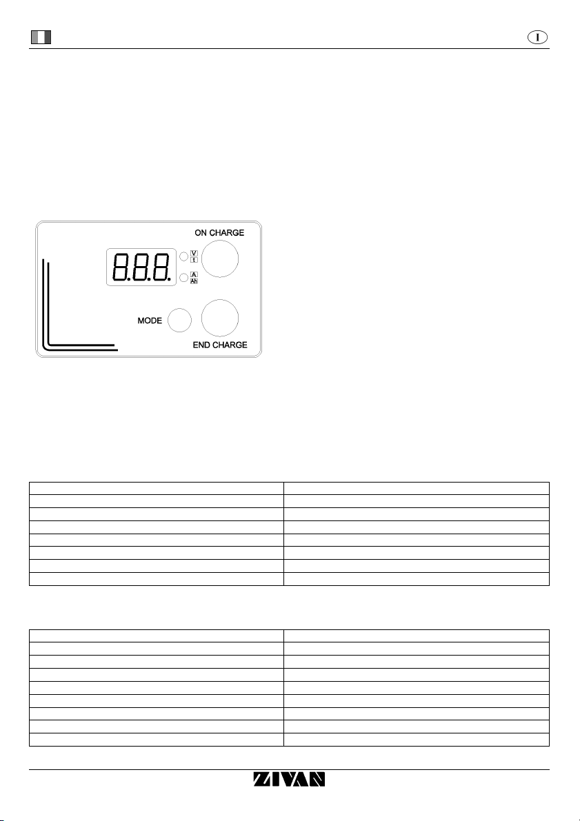
SG6 CAN Bus Interface Italiano
D01596-03
3
ATTENZIONE - Non rimuovere il coperchio:
pericolo di scosse elettriche.
Rivolgersi solo a personale autorizzato.
Scollegare l’alimentazione prima di collegare
o scollegare le connessioni alla batteria.
Durante il funzionamento è possibile che alcune parti
del prodotto raggiungano temperature elevate.
Prima dell’utilizzo, leggere attentamente
il libretto di istruzioni. Verificare che
la curva di carica selezionata sia adatta al
tipo di batteria che si deve ricaricare.
Spiegazione dei simboli grafici:
Avverte l’utente della presenza di “tensione pericolosa” non isolata
dentro il contenitore del prodotto; questa può essere di ampiezza
sufficiente per costituire un rischio di scosse elettriche per le persone.
Avverte l’utente che alcune superfici di contatto
potrebbero raggiungere temperature elevate.
Avverte l’utente della presenza di importanti istruzioni d’uso e
manutenzione (servizio) contenute nella documentazione allegata al
prodotto.
Questa apparecchiatura è coperta da garanzia. Il relativo certificato di garanzia si trova allegato al libretto di istruzioni.
Se dovesse mancare, richiedetelo al vostro rivenditore.
Le informazioni contenute in questo manuale sono di proprietà ZIVAN S.r.l. che si riserva di fornirle ad uso esclusivo dei propri clienti.
Nessun altro uso è permesso senza un’autorizzazione scritta emessa da ZIVAN S.r.l..
ZIVAN S.r.l. non risponde delle possibili inesattezze, imputabili a errori di stampa o di trascrizione, contenute nel presente manuale.
Si riserva di apportare ai propri prodotti quelle modifiche che ritenesse necessarie o utili, anche nell’interesse dell’utenza, senza
pregiudicare le caratteristiche essenziali di funzionalità e sicurezza.
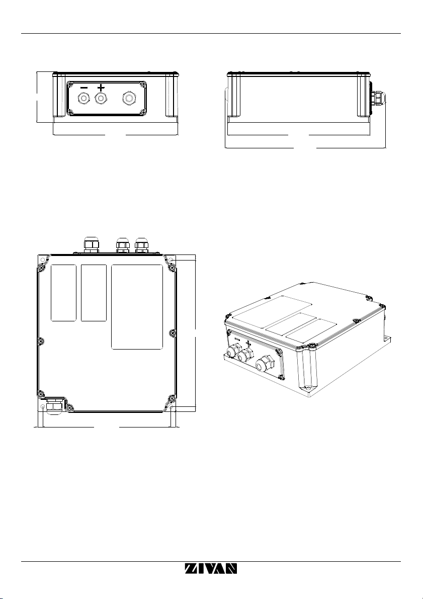
DESTINAZIONE D’USO
Il carica batteria SG6 è un’apparecchiatura elettronica, solo per uso professionale, progettata per consentire la ricarica di batterie di tipo
diverso a seconda del firmware installato. A seconda dell’applicazione e del firmware installato è consentito l’uso come alimentatore.
Installazione e istruzioni di sicurezza
Il carica batteria SG6 è stato progettato per garantire sicurezza e prestazioni affidabili. Tuttavia, onde evitare danni alla propria persona e al
carica batteria, si raccomanda di osservare le seguenti precauzioni di base:
•Leggere attentamente le istruzioni di installazione contenute in questo manuale. Per futuri riferimenti, riporre il manuale in posto sicuro.
•Non posizionare il carica batteria nei pressi di fonti di calore.
•Assicurarsi che l’area limitrofa al caricabatteria sia tenuta sgombra da materiali facilmente infiammabili.
•Essendo il caricabatteria sigillato e privo di ventilazione forzata, le prestazioni dipendono dalla temperatura e dal tipo di installazione.
Quindi si consiglia l’installazione su piastra dissipante o analoga soluzione. Per aumentare la dissipazione termica è possibile
aggiungere dissipatori esterni eventualmente anche ventilati.
•Verificare che il tipo di alimentazione a disposizione corrisponda al voltaggio previsto e indicato nella targhetta del carica batteria. In
caso di dubbio, consultare il proprio rivenditore o la società elettrica locale.
•Come dispositivo di protezione nell’alimentazione del caricabatteria può essere utilizzato un interruttore differenziale di classe AC, ma
si consiglia l’utilizzo di uno di classe A o ancora meglio uno di classe B.
•Come dispositivo di sicurezza e di compatibilità elettromagnetica, il carica batteria dispone di una spina a tre poli con messa a terra
che può essere inserita soltanto in una presa con messa a terra. Nel caso in cui non sia possibile inserire la spina nella presa, è molto
probabile che la presa a disposizione sia di un tipo vecchio e non a terra. In tal caso, contattare un elettricista per far sostituire la presa.
Si raccomanda di non usare un adattatore per risolvere il problema della messa a terra.
•Evitare che il cavo di alimentazione sia in una posizione di ingombro. Nel caso in cui il cavo diventi logoro o subisca danni, farlo
sostituire immediatamente.
•Nel caso in cui si usi una prolunga o una presa multipla, verificare che queste supportino il totale della corrente richiesta.
•Scollegare l’alimentazione prima di collegare o scollegare le connessioni alla batteria.
•Per la ricarica di batterie al Piombo: ATTENZIONE: Gas esplosivi - Evitare la formazione di fiamme e scintille. - La batteria deve essere
posizionata in un luogo ben ventilato.
•Non utilizzare per ricarica di batterie per avviamento installate a bordo di automobili a motore termico.
•Evitare di ricaricare batterie non ricaricabili.
•Verificare che la tensione nominale della batteria da ricaricare corrisponda a quella indicata nella targhetta del carica batteria.
•Verificare che la curva di carica selezionata sia adatta al tipo di batteria che si deve ricaricare. In caso di dubbio, consultare il proprio
rivenditore. La ZIVAN S.r.l. declina ogni responsabilità nel caso di errore nella scelta della curva di carica che porti a un
danneggiamento irreversibile della batteria.
•Per evitare cadute di tensione e così garantire la carica completa della batteria, i cavi di uscita devono essere più corti possibile e di
sezione adeguata alla corrente di uscita.
•Nel caso di compensazione termica della tensione di batteria, posizionare la sonda termica nel punto più caldo del vano batterie.
•Non tentare di effettuare riparazioni sul carica batteria. L’apertura del coperchio potrebbe esporvi al rischio di scosse elettriche.
•Non aprire il caricabatteria, l’apertura potrebbe portare a una perdita del grado di protezione (IP) che permarrebbe anche dopo aver
ripristinato le chiusure.
•Nell’eventualità che il carica batteria non funzioni in modo corretto o che sia danneggiato, scollegarlo immediatamente dalla presa di
corrente e dalla presa di batteria e contattare il rivenditore.