ZOLL E SERIES EtCO2 User manual

October 2007 9650-1212-01 Rev. E
End Tidal Carbon
Dioxide (EtCO2)

The issue date or revision level for this Operator’s Guide is shown on the front cover.
ZOLL and E Series are registered trademarks of ZOLL Medical Corporation.
CAPNOSTAT is a registered trademark and LoFlo and CAPNO2mask are trademarks of Respironics
Novametrix LLC.
Cidex is a registered trademark of Advanced Sterilization Products, a Johnson & Johnson Company.
Nafion is a registered trademark of DuPont.
System 1 is a registered trademark of the Steris Corporation.
©2007 by ZOLL Medical Corporation. All rights reserved.

9650-1212-01 Rev. E 1
END-TIDAL CARBON DIOXIDE (EtCO2)
General Information
Product Description
ESeries
®units equipped with software revision 2.00.000 or higher support two End Tidal Carbon Dioxide (EtCO2)
monitoring options for the continuous measurement of respiratory carbon dioxide (CO2) and respiration rate. These
options use the same connector on the E Series unit and may be used interchangeably.
The first option uses a unique, mainstream, solid-state, infrared sensor called the CAPNOSTAT®5 Mainstream CO2
Sensor. The CAPNOSTAT 5 CO2sensor is attached to an airway adapter that connects to an endotracheal (ET) tube
or other airway and measures gases flowing through these breathing circuit components. A disposable mouthpiece
may be connected to the adapter for monitoring non-intubated patients. A CAPNO2mask™ is also available for use
with non-intubated patients. This option provides for O2delivery while monitoring expired CO2.
The second option is a sidestream sampling system called the LoFlo™ CO2 Module. The LoFlo module contains a gas
sampling pump, which draws small samples of gas from the patient’s airway via a nasal/oral cannula or airway adapter,
and passes these gases through a solid state infrared sensor (located away from the patient’s airway) that measures
CO2. While the sidestream system is typically used on non-intubated patients, it can also be used for EtCO2
measurement on intubated infant, pediatric and adult patients. The sidestream system should not be used, however,
on patients who cannot tolerate the 50ml/min removal of the sample gases from their breathing circuit. The sidestream
module uses specially designed cannulas and airway adapters for sampling airway gases and passing them through
an integrated sample cell, which connects to the LoFlo module’s CO2sensor. These cannulas incorporate a filter and
sample cell, providing maximum filtration of fluids and contaminants, and protecting the system from aspiration of
these fluids.
In both systems, the CO2 sensor generates infrared light and beams it through the airway adapter or sample cell to a
detector on the opposite side. CO2from the patient, flowing through the mainstream airway adapter or sample cell,
absorbs some of this infrared energy. The E Series unit determines CO2concentration in the breathing gases by
measuring the amount of light absorbed by gases flowing through the airway or sample cell.
The E Series unit displays EtCO2(the concentration of carbon dioxide detected at the end of each exhalation) as a
numerical value in millimeters of mercury (mmHg), percent (%), or kilopascals (kPa). In addition, the unit can display a
capnogram. This capnogram is a valuable clinical tool that can be used to assess patient airway integrity and proper
endotracheal (ET) tube placement. The unit calculates respiration rate by measuring the time interval between
detected peaks of the CO2waveform. The technology differentiates between waveforms caused by breathing and
those caused by cardiogenic oscillations and artifact.
How to Use This Manual
This section explains how to set up and use the E Series End Tidal Carbon Dioxide option. Important safety
information relating to general use of the E Series End Tidal Carbon Dioxide monitor appears in the “Safety
Considerations” section of this manual.
The E Series Operator’s Guide provides information operators need for the safe and effective use and care of the
ESeriesunit. It is important that persons using this device read and understand all the information contained therein.
Please read both safety considerations and warnings sections thoroughly before operating your E Series unit.
All CAPNOSTAT 5 sensor, LoFlo module, airway adapter and cannula questions with regards to the Declaration of
Conformity with European Union Directives should be directed to the authorized representative for Respironics
Novametrix LLC:
Respironics Novametrix LLC
Authorized European Contact
Respironics Deutschland
Gewerbestrasse 17
82211 Herrsching
Germany
+49 8152 93060

E Series - End Tidal Carbon Dioxide (EtCO2) Option Insert
29650-1212-01 Rev. E
Safety Considerations
WARNINGS
General
• Carefully read the E Series Operator’s Guide and
these operating instructions before operating the
EtCO2monitoring option.
• Ensure that the E Series EtCO2option is operated
by qualified personnel only.
• Do not use the E Series EtCO2option as an apnea
monitor.
• Do not immerse the E Series unit, patient cables, or
sensors in water, solvents, or cleaning solutions.
• If the accuracy of any reading is suspect, first check
the patient’s vital signs by alternate means and then
check the E Series EtCO2option for proper
operation.
• If an alarm condition occurs while the alarms are
suspended, the suspended alarm indications will
only be visual displays and symbols. No audio alarm
indications will occur.
• Elevated oxygen levels, nitrous oxide, or
halogenated agents contained in the breathing
gases may degrade the accuracy of measurements
made with the E Series EtCO2option. Activate
oxygen compensation if O2levels in excess of 60%
are introduced. Activate N2O compensation if nitrous
oxide is introduced into the airway circuit. The
presence of Desflurane beyond 5% may positively
bias the carbon dioxide reading by up to 3 mmHg.
• Do NOT use the LoFlo module on patients who
cannot tolerate the removal of 50ml/min of breathing
gases from the airway.
• Carefully route patient cabling to reduce the
possibility of patient entanglement or strangulation.
• Do not touch the bed, patient, or any equipment
connected to the patient during defibrillation. A
severe shock can result. Do not allow exposed
portions of the patient’s body to come in contact with
metal objects, such as a bed frame, as unwanted
pathways for defibrillation current may result.
CAPNOSTAT and Accessories
• Always ensure the integrity of the patient breathing
circuit after insertion of the airway adapter by
verifying a proper CO2waveform (capnogram) on
the monitor display.
• Do not use CAPNOSTAT 5 or LoFlo sensors in the
presence of flammable anesthetics or other
flammable gases.
• Do not attempt to open the sensor. An electrical
shock hazard exists internally. Refer servicing to
qualified personnel.

9650-1212-01 Rev. E 3
Safety Considerations
CAUTIONS
• CAUTION: Federal (U.S.A.) law restricts this device
to sale, or use by or on the order of a licensed
medical practitioner.
• Use only ZOLL/Respironics Novametrix
CAPNOSTAT 5 sensors and LoFlo modules, airway
adapters, nasal and nasal/oral cannula sets with the
E Series EtCO2option.
•The device is protected against interference from
radio frequency emissions typical of two-way radios
and cellular phones (digital and analog) used in
emergency service/public safety activities. Users
should assess the device’s performance in their
typical environment of use for the possibility of radio
frequency interference from high-power sources.
Radio Frequency Interference (RFI) may be
observed as shifts in monitor baseline, trace
compression,displaybrightnesschangesortransient
spikes on the display.
• Do NOT sterilize or immerse the CAPNOSTAT 5
CO2 sensor or LoFlo module.
• Do NOT reuse or sterilize the disposable airway
adapter, airway adapter with mouthpiece,
CAPNO2mask, nasal or nasal/oral sampling cannula
sets, or airway adapters, as system performance will
be compromised. These items are intended for
single patient use only.
• Do NOT use a damaged sensor or airway adapter.
• Do NOT use the device if it fails to operate properly.
• Do NOT place the mainstream or sidestream airway
adapters between the ET tube and the breathing
circuit elbow, as this may allow patient secretions to
accumulate in the adapter.
• Position airway adapters with windows in a vertical,
NOT a horizontal, position. This helps keep patient
secretions from pooling on the windows.
• Do NOT insert any object other than the sample cell
into the sample cell receptacle on the LoFlo module.
• Remove the LoFlo sample cell from the sample cell
receptacle when not in use.
• Clean or replace the airway adapter if excessive
secretions are observed.
• ZOLL Medical Corporation recommends that the
airway adapter be removed from the circuit
whenever aerosolized medication is delivered. The
increased viscosity of the medications may
contaminate the adapter windows, requiring
premature cleaning or replacement of the adapter.
• In order to eliminate the potential build up of CO2
inside the storage bag, ensure that the LoFlo module
exhaust tube vents gases away from the module
environment.
• To avoid injury to the patient, remove the nasal/oral
cannula from the patient before cutting the oral
cannula tip.
• Do NOT apply tension to the sensor cable.
• Periodically inspect the sampling tubing for the
absence of kinks.
• Monitor the capnogram for an elevated baseline. If
an elevated baseline is observed, verify patient
condition first. If the care giver determines that the
patient condition is not contributing to the elevated
baseline, follow the instructions for zeroing the
sensor or module detailed in this manual.
• Do NOT store sensors, modules, airway adapters, or
cannula sets at temperatures less than -40° C or
greater than 70° C.
• Do not operate CAPNOSTAT sensors at
temperatures less than 0° C or greater than 45° C.
Do not operate LoFlo modules at temperatures less
than 0° C or greater than 40° C.
• Refer servicing to qualified personnel.
• Do not use the LoFlo module on E Series units that
have a software version lower than 2.00.000.

E Series - End Tidal Carbon Dioxide (EtCO2) Option Insert
49650-1212-01 Rev. E
EtCO2Indications for Use
The ZOLL E Series EtCO2 option is indicated for the
continuous noninvasive monitoring of end tidal carbon
dioxide (EtCO2) and respiration rate in patients requiring
ventilator support, transport, or anesthesia. The E Series
EtCO2option with Respironics Novametrix technology
supports two methods for continuous measurement of
end tidal carbon dioxide (EtCO2) and respiration rate.
The first method uses the CAPNOSTAT 5 Mainstream
CO2 sensor attached to an airway adapter that connects
to an endotracheal tube, mask or disposable
mouthpiece.
The second method uses the LoFlo CO2module to
monitor both non-intubated and intubated patients using
specially designed sampling cannulas and airway
adapters.
The E Series EtCO2option is designed to monitor adult,
pediatric, and neonatal patients.
The following substances can influence CO2
measurements made with the CAPNOSTAT 5 CO2
sensor:
•elevated oxygen levels
•nitrous oxide
•halogenated agents
The E Series EtCO2option allows high oxygen and/or
nitrous oxide compensation. Halogenated anesthetic
agents alter CO2 readings, but the E Series unit will
monitor CO2 within specifications when these agents are
present at normal clinical levels. The presence of
Desflurane in the exhaled breath beyond normal values
(5-6%) may positively bias measured carbon dioxide
values by up to an additional 2-3 mmHg.
The E Series EtCO2option is intended for use only with
the ZOLL/Respironics Novametrix CAPNOSTAT 5
Mainstream CO2 Sensor and the LoFlo CO2Module,
mainstream airway adapters, nasal and nasal/oral
sampling cannula sets, and sidestream on-airway
adapters.
Mainstream EtCO2Setup
There are several steps involved with mainstream
EtCO2 setup. These steps include:
•Attaching the CAPNOSTAT sensor cable.
•Selecting a mainstream airway adapter.
•Attaching the airway adapter to the CAPNOSTAT
sensor.
• Zeroing the CAPNOSTAT sensor/airway adapter.
• Attaching the airway adapter to the airway circuit.
•Applying an airway adapter with mouthpiece.
Attaching the CAPNOSTAT 5 CO2 Sensor Cable
To attach the CAPNOSTAT 5 CO2 sensor cable, plug the
cable’s connector into the yellow CO2connector at the
back of the E Series unit by matching the key on the
cable to the key on the connector (Figure 1).
Note To remove the sensor cable from the E Series unit,
grasp the collar surrounding the cable’s E Series
connector and pull up.
Selecting a Mainstream Airway Adapter
Select an airway adapter based on the patient's size, ET
tube diameter and monitoring situation. For more
information refer to the following table or contact ZOLL
Medical Corporation.
*SPU = Single Patient Use
Attaching the Airway Adapter to the
CAPNOSTAT 5 CO2Sensor
Before attaching the airway adapter to the
CAPNOSTAT 5 CO2 sensor, verify that the airway
adapter windows are clean and dry. Clean or replace the
adapter if necessary.
CAUTION! The disposable (SPU) Pediatric/Adult and
the Neonatal/Pediatric airway adapters are
intended for single patient use. Do NOT
reuse or sterilize these adapters as system
performance will be compromised.
Attach the airway adapter to the CAPNOSTAT sensor,
as follows:
1. Align the arrow on the bottom of the airway adapter
with the arrow on the bottom of the sensor.
Airway Adapter Type ET Tube Diameter
SPU*Pediatric/Adult > 4.0 mm
Adult Reusable > 4.0 mm
SPU* Neonatal/Pediatric ≤4.0 mm
Neonatal Reusable ≤4.0 mm
Proper Grasp Improper Grasp
Figure 1

Mainstream EtCO2 Setup
9650-1212-01 Rev. E 5
2. Press the sensor and airway adapter together until
they click.
3. Turn the Selector switch on the E Series unit to
MONITOR (ON for AED units).
4. Wait for the airway adapter and sensor to warm up.
The unit will display a WARM UP message for
approximately one minute while the sensor and
adapter warm to operating temperature. The
message disappears when the sensor is ready to
use.
Note Warm up time varies with ambient temperature of
the sensor.
5. If the unit displays the CHECK CO2 ADAPTER
message, follow steps a through c.
a. Verify proper connection of the adapter to the
sensor.
b.Verify that the airway adapter windows are clean
and dry.
c. If the adapter is properly connected, and the
windows are clean and dry, then zero the adapter
as described in the next section, “Zeroing the
Mainstream CAPNOSTAT 5 CO2Sensor/Airway
Adapter.”
Zeroing the Mainstream CAPNOSTAT 5 CO2
Sensor/Airway Adapter
Adapter zeroing compensates for the optical differences
between airway adapters and should be performed after
switching between single patient use and reusable
airway adapters, in order to obtain accurate readings.
Zeroing is also recommended the first time a particular
CAPNOSTAT 5 CO2 sensor is connected to the unit.
1. Place the sensor with the adapter installed away from
all sources of CO2 (including the patient’s – and your
own – exhaled breath and ventilator exhaust valves).
2. Press the Param. softkey and select the EtCO2
menu item, then press Enter.
3. Press the Zero softkey.
The unit zeroes the adapter and displays the
ZEROING CO2 ADAPTER message for 15 to 20
seconds.
The unit displays the message ZERO DONE upon
completion of the zeroing.
Note Do not attempt zeroing for 20 seconds after
removing the adapter from the patient’s airway.
This time allows any CO2 remaining in the adapter
to dissipate before zeroing. Do not attempt to zero
the adapter while it is connected to the patient’s
airway. Zeroing with CO2 in the adapter can lead to
inaccurate measurement and/or other error
conditions. If you attempt zeroing while CO2
remains in the adapter, the time required to zero
the adapter may be increased. If zeroing cannot be
completed, the message ZERO FAILED will be
displayed. If this occurs, clear any occlusion in the
adapter, remove any source of CO2, wait 20
seconds, and try zeroing again.
Attaching the Airway Adapter to the Airway
Circuit
If you have not yet done so, you must attach the airway
adapter to the CAPNOSTAT 5 CO2 sensor before
attaching the airway adapter to the airway circuit. Refer
to “Attaching the Airway Adapter to the CAPNOSTAT 5
CO2 Sensor” on page 4 if necessary.
Attach the airway adapter to the airway circuit as follows:
1. Place the CAPNOSTAT 5 CO2 sensor/airway adapter
assembly at the proximal end of the airway circuit
between the elbow and the ventilator circuit wye. Do
NOT place the airway adapter between the ET tube
and the elbow, as this may allow patient secretions to
accumulate in the adapter.
Position the airway adapter with its windows in a
vertical, NOT a horizontal, position. This helps keep
patient secretions from pooling on the windows. If
pooling does occur, the airway adapter may be
removed from the circuit, rinsed with water and
reinserted into the circuit. To prevent moisture from
draining into the airway adapter, do NOT place the
airway adapter in a gravity dependent position. See
Figure 2.
2. Check that connections have been made correctly by
verifying the presence of a proper CO2 waveform on
the E Series display.
3. The sensor cable should face away from the patient.
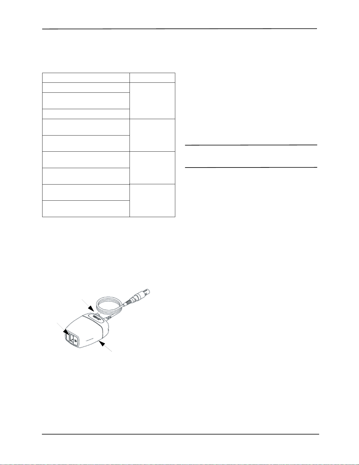
Figure 2
CAPNOSTAT
CO
2
Sensor
To Patient
Reusable Adult
Airway Adapter
Ventilator Wye

E Series - End Tidal Carbon Dioxide (EtCO2) Option Insert
69650-1212-01 Rev. E
Applying an Airway Adapter with Mouthpiece
The disposable Pediatric/Adult airway adapter with
mouthpiece can be used for spot checking CO2 on
non-intubated adult or pediatric patients.
CAUTION! The disposable Pediatric/Adult Airway
Adapter with mouthpiece is intended for
single patient use. Do NOT reuse or sterilize
the adapter, as system performance will be
compromised.
1. Remove adapter with mouthpiece from the package.
Verify that the adapter and mouthpiece are intact and
securely fastened to each other.
2. Attach the airway adapter to the CAPNOSTAT 5 CO2
sensor, as follows:
a.Align the arrow on the bottom of the airway adapter
with the arrow on the bottom of the CAPNOSTAT
sensor.
b.Press the sensor and airway adapter together until
they click (see Figure 3).
3. If the unit displays the CHECK CO2 ADAPTER
message, follow steps a through c, else go to step 4.
a.Verify proper connection of the adapter to the
sensor.
b.Verify that the airway adapter windows are clean
and dry.
c. If the adapter is properly connected, and the
windows are clean and dry, then zero the adapter
as described in “Zeroing the Mainstream
CAPNOSTAT 5 CO2 Sensor/Airway Adapter” on
page 5.
4. Ensure the patient seals his or her mouth completely
around the mouthpiece and breathes normally.
A nose clip may be needed if the patient is exhaling
through the nose. It is important that all, or most, of the
exhalation be routed through the airway adapter.
Sidestream EtCO2Setup
There are several steps involved with sidestream EtCO2
setup. These steps include:
• Attaching the LoFlo Module Cable
• Selecting a Sidestream Airway Adapter Kit or
Cannula
• Inserting the Sample Cell
• Zeroing the LoFlo CO2Module/Sample Cell
• Applying a Sidestream Airway Adapter Kit
• Applying a Nasal or Nasal/Oral Cannula
Attaching the LoFlo Module Cable
To attach the LoFlo module cable, plug the cable into the
yellow CO2connector at the back of the E Series unit by
matching the key on the cable to the key on the
connector.
To remove the sensor cable from the E Series unit,
grasp the collar surrounding the cable’s E Series
connector and pull up.
Selecting a Sidestream Airway Adapter Kit
Select an airway adapter kit based on the patient's size,
ET tube diameter, and monitoring situation. Airway
adapter kits are disposable and single patient use.
Note For monitoring times exceeding 6 hours, Nafion
tubing is recommended.
Figure 3
CO
2
Sensor
CAPNOSTAT
Mouthpiece
To Patient
Airway
Adapter
Airway Adapter Kit ET Tube
Diameter
Adult/Pediatric Airway Adapter Kit > 4.0 mm
Adult/Pediatric Airway Adapter Kit
with Nafion® tubing
Pediatric/Infant Airway Adapter Kit ≤4.0 mm
Pediatric/Infant Airway Adapter Kit
with Nafion tubing
Proper Grasp Improper Grasp
Figure 4

Sidestream EtCO2 Setup
9650-1212-01 Rev. E 7
Selecting a Sidestream Cannula
Select a sidestream cannula based on the patient's size
and monitoring situation. Nasal and nasal/oral cannulas
are disposable and single patient use.
Inserting the Sample Cell
Follow these steps:
1. Remove the LoFlo sampling cannula or airway
adapter kit from the package.
2. Insert the LoFlo sample cell into the LoFlo sample
cell receptacle and ensure that it clicks into place.
3. Ensure that the LoFlo module exhaust tube vents
gases away from the module environment.
4. Turn the selector switch on the E Series to
MONITOR (ON for AED units).
5. Wait for the CO2 module to warm up.
The unit will display the WARM UP message for
approximately one minute while the module warms
up to operating temperature. The message
disappears when the module is ready for use.
Note Warm up time varies with ambient temperature of
the module.
Zeroing the LoFlo CO2Module/Sample Cell
The module/sample cell zero allows the LoFlo CO2
module to adjust to the optical characteristics of the
sample cell. While zeroing is recommended the first time
a particular LoFlo module is connected to the unit, it is
only absolutely necessary when the message ZERO
CO2 MODULE is displayed.
CAUTION! Always ensure that the sample cell is
properly connected to the LoFlo module
before zeroing.
1. Ensure that the nasal cannula or on-airway adapter is
not connected to the patient or close to any source of
CO2 (including the patient's -- and your own --
exhaled breath and ventilator exhaust valves).
2. Press the Param. softkey and select the EtCO2menu
item, then press Enter.
3. Press the Zero softkey.
The unit zeroes the module and displays the
ZEROING CO2 MODULE message for
approximately 15-20 seconds.
The units displays the message ZERO DONE upon
completion of the zeroing.
Note Do not attempt zeroing for 20 seconds after
removing the adapter or cannula from the patient’s
airway. This time allows any CO2remaining in the
adapter or cannula to dissipate before zeroing. Do
not attempt to zero the module while the adapter or
cannula is in the patient’s airway. Zeroing with CO2
in the adapter or cannula can lead to inaccurate
measurements and/or other error conditions. If you
attempt zeroing while CO2 remains in the adapter
or cannula, the time required to zero the module
may be increased. If zeroing cannot be completed,
the message “ZERO FAILED” will be displayed. If
this occurs, clear any occlusion in the adapter or
cannula, remove the source of CO2, wait 20
seconds, and try zeroing again.
Applying a Sidestream Airway Adapter Kit
The sidestream airway adapter kit is intended for
monitoring the EtCO2of intubated patients.
Before attaching the airway adapter to the breathing
circuit, verify that the adapter is clean, dry, and
undamaged. Replace if necessary.
Cannula Application
Nasal CO2Sampling Cannula, Adult Nasal CO2
sampling only
Nasal CO2Sampling Cannula,
Pediatric
Nasal CO2Sampling Cannula, Infant
Oral/Nasal CO2Sampling Cannula,
Adult Oral/Nasal CO2
sampling only
Oral/Nasal CO2Sampling Cannula,
Pediatric
Nasal CO2Sampling with O2Delivery
Cannula, Adult Nasal CO2
sampling with
oxygen delivery
Nasal CO2Sampling with O2Delivery
Cannula, Pediatric
Oral/Nasal CO2Sampling with O2
Delivery Cannula, Adult Oral/Nasal CO2
sampling with
oxygen delivery
Oral/Nasal CO2Sampling with O2
Delivery Cannula, Pediatric
Module Cable
Sample Cell
Receptacle
LoFlo C5 Module
Exhaust
Tube
Figure 5
LoFlo Module

E Series - End Tidal Carbon Dioxide (EtCO2) Option Insert
89650-1212-01 Rev. E
CAUTION! The disposable (SPU) Adult/Pediatric and
Pediatric/Infant airway adapter kits are
intended for single patient use. Do NOT
reuse or sterilize these adapters as system
performance will be compromised.
1. Attach the airway adapter kit’s sample cell to the
sample cell receptacle on the LoFlo module, and
ensure that it clicks into place.
2. If the unit displays either of the following messages
take the appropriate action.
3. Place the airway adapter assembly at the proximal
end of the airway circuit between the elbow and the
ventilator circuit wye. Do NOT place the airway
adapter between the ET tube and the elbow as this
may allow patient secretions to accumulate in the
adapter.
If pooling does occur, the airway adapter may be
removed from the circuit, rinsed with water and
reinserted into the circuit. To prevent moisture from
draining into the sample tubing, ensure that the
sampling tube exits from the top of the airway
adapter, not its bottom or sides. See Figure 6.
4. Check that connections have been made correctly by
verifying the presence of a proper capnogram on the
E Series display.
Applying a Nasal or Nasal/Oral Cannula
The nasal and nasal/oral cannulas are intended for
monitoring EtCO2in non-intubated patients.
Oral/nasal sampling cannulas should be used on
patients who are prone to mouth breathing, since most (if
not all) of the CO2 is exhaled through the mouth. If a
standard nasal CO2 sampling cannula is used on such
patients, the EtCO2values and capnogram displayed will
be substantially lower than the actual CO2 levels present
in the patient’s expired breath.
CAUTION! The disposable nasal and nasal/oral
cannula sets are intended for single patient
use. Do NOT reuse or sterilize the cannula,
as system performance will be
compromised.
1. Remove the cannula from the package. Verify that
the cannula is clean, dry, and undamaged. Replace if
necessary.
2. Attach the cannula’s sample cell to the sample cell
receptacle on the LoFlo module, and ensure that it
clicks into place.
3. If the unit displays either of the following messages
take the appropriate action.
If you see this
message: Take this action:
CHECK CO2
LINE Verify that the sample cell is plugged
into the module and seated properly.
Verify that neither the sample line nor
the exhaust tube are blocked, kinked,
or pinched. Verify that the airway
adapter is not blocked. If the sample
line, exhaust tube, or the airway
adapter is blocked or otherwise
compromised for 15 seconds, this
message will appear. The pump will
shut offafter 2 minutes if the condition
that caused the message is not
cleared. To restart the pump, correct
the blockage, then remove and
reinsert the sample cell into the
sample cell receptacle.
If the problem persists, replace the
sample line.
CHECK CO2
MODULE Check that module cable is plugged in
and seated properly.
Check that module is not exposed to
excessive heat.
If problem persists, replace module.
Figure 6
Sampling Tube

Cleaning the CAPNOSTAT 5 CO2 Sensor and LoFlo Module
9650-1212-01 Rev. E 9
4. Place the nasal cannula onto the patient as shown in
Figure 7.
5. Place the oral/nasal cannula onto the patient as
shown in Figure 8.
Cleaning the CAPNOSTAT 5 CO2
Sensor and LoFlo Module
The outside of the sensor or module may be cleaned and
disinfected by wiping with 70% isopropyl alcohol, a 10%
bleach solution, or mild soap.
After cleaning, wipe with a clean, water-dampened cloth
to rinse. Dry before use.
Cleaning Reusable Airway Adapters
Reusable airway adapters may be cleaned by rinsing in
a warm soapy solution, followed by soaking in a liquid
disinfectant such as 70% isopropyl alcohol, a 10%
bleach solution, Cidex® or System 1® (refer to the
disinfectant manufacturer's instructions for use).
Adapters should then be rinsed with sterile water and
dried.
Reusable airway adapters may also be pasteurized or
autoclaved. Autoclave at 121° C (250° F) for 20 minutes,
unwrapped.
Before reusing the adapter, ensure the windows are dry
and residue-free, and that the adapter has not been
damaged during handling or by the cleaning process.
If you see this
message: Take this action:
CHECK CO2
LINE Verify that the sample cell is plugged
into the module and seated properly.
Verify that neither the sample line nor
the exhaust tube are blocked, kinked,
or pinched. If the sample line, or
exhaust tube is blocked or otherwise
compromised for 15 seconds, this
message will appear. The pump will
shut off after 2 minutes if the condition
that caused the message is not
cleared. To restart the pump, correct
the blockage, then remove and
reinsert the sample cell into the
sample cell receptacle.
If the problem persists, replace the
sample line.
CHECK CO2
MODULE Check that module cable is plugged in
and seated properly.
Check that module is not exposed to
excessive heat.
If problem persists, replace module.
Figure 7
Figure 8

E Series - End Tidal Carbon Dioxide (EtCO2) Option Insert
10 9650-1212-01 Rev. E
How EtCO2is Displayed
The E Series unit displays the numeric EtCO2value in
units of mmHg, unless configured for percent or kPa.
Refer to the E Series Configuration Guide (Part No.
9650-1201-01) for instructions on how to configure
alternate units of measure. The unit also displays the
number of breaths per minute, labeled "RR" for
respiration rate. In addition, a capnogram may be
displayed using the Wave 2 softkey.
Displaying the Capnogram Waveform
The E Series unit can display one or two waveforms in
Monitor, Defib, or Manual (AED) mode, as long as the
defibrillator is not charging or ECG analysis is not in
progress. The unit displays only one waveform in Pacer
mode.
Note Ifyou don’tseethe CO2displaybox onthemonitor,
check the sensor cable connection to the E Series
unit. The CO2box is not displayed if the sensor is
not connected to the unit. Once the box is
displayed, after power-on, it remains displayed
even if the sensor is disconnected from the unit.
With EtCO2monitoring, the unit can display a capnogram
below the ECG trace for a visual indicator of the
moment-by-moment CO2values. The unit displays the
capnogram at half the speed of the ECG display, and
provides 8 seconds of data.
The unit temporarily removes the second waveform from
the display when the user presses the CHARGE,
ANALYZE, or ENERGY SELECT buttons, or the Sync
On/Off softkey. The unit restores the second waveform
to the display 4 seconds after:
• a shock is delivered
• an analysis is completed, unless the defibrillator is
charging
• the last Energy Select button press
• Sync mode is turned off
To cycle the display from the capnogram, to the
plethysmograph waveform (if SpO2is installed), to no
second waveform displayed, press the Wave 2 softkey.
Use the Zoom softkey from the EtCO2submenu to
adjust the waveform display size. Numbers shown on the
left side of the capnogram display indicate the scaling.
Physiological Monitoring
The physiological monitoring menu includes the
following softkeys: Param, Wave 2, ID#, Alarms, and 12
Lead.
Param Softkey
When you press the Param softkey, the following
softkeys are displayed: Select, Enter, and Return.
Press the:
•Select softkey to scroll among the different available
physiological parameters.
•Enter softkey to select the parameter that is
highlighted.
•Return softkey to return to the physiological
monitoring menu.
Selecting the EtCO2 parameter causes the following
softkeys to appear: Zero, Disable EtCO2 (or Enable
EtCO2), Zoom, MORE, and Return.
Pressing the:
•Disable EtCO2 softkey puts the sensor into the
power saving sleep mode.
•Enable EtCO2 takes the sensor out of sleep mode
and turns the heater on for normal operation.
•MORE softkey causes the following softkeys to
appear: Average, Comp., RR Filter Disable, (or RR
Filter Enable), MORE, and Return.
•Return softkey returns you to the physiological
monitoring menu.
See the next sections for a description of the Zero and
Zoom softkey functions.
Pressing the MORE softkey causes the previous
selections to appear. Pressing the Return softkey returns
the user to the physiological monitoring menu. Refer to
the sections “Average Softkey,” “Comp. Softkey,” and
“RR Filter Enable/Disable” for descriptions of those
softkey functions.
3DUDP :DYH $ODUPV /HDG
,'
6S2
(&*
3$'6
[
(&*
&2
&2
P
P
+J
55
(QWHU
6HOHFW
5HWXUQ
6S2
(W&2
1,%3
'LVDEOH
(W&2
=HUR
5HWXUQ
025(
=RRP
&RPS
$YHUDJH
5HWXUQ
025(

Physiological Monitoring
9650-1212-01 Rev. E 11
Zero Softkey
Adapter zeroing should be performed whenever you
change between reusable and disposable adapters.
Module zeroing may be necessary if the unit displays the
message ZERO CO2 MODULE. Adapter zeroing may
also be necessary if the unit displays CHECK CO2
ADAPTER.
Note Do not attempt zeroing for 20 seconds after
removing the adapter or cannula from the patient’s
airway. This time allows any CO2remaining in the
adapter or cannula to dissipate before zeroing. Do
not attempt to zero while the adapter or cannula is
in the patient’s airway. Zeroing with CO2 in the
adapter or cannula can lead to inaccurate
measurements and/or other error conditions. If you
attempt zeroing while CO2 remains in the adapter
or cannula, the time required to zero may be
increased. If zeroing cannot be completed, the
message ZERO FAILED will be displayed. If this
occurs, clear any occlusion in the adapter or
cannula, remove any source of CO2, wait 20
seconds, and try zeroing again.
Pressing the Zero softkey initiates adapter or module
zeroing.
The unit displays the ZEROING CO2 ADAPTER or
ZEROING CO2 MODULE message during the zeroing
process, which is typically finished in 15 - 20 seconds.
The unit displays the ZERO DONE message when the
zeroing process is complete.
The unit displays the ZERO FAILED message if the
zeroing process did not complete successfully. If this
occurs, clear any occlusion in the adapter or sample line,
remove any source of CO2, and try zeroing again.
Pressing Return returns the user to the EtCO2submenu.
Zoom Softkey
Select the full scale range for the displayed capnogram
by pressing the Zoom softkey to scroll among the
different zoom levels. Zoom levels change with each
press of the Zoom softkey. They are as follows:
• 0-12.5 mmHg
• 0-25 mmHg
• 0-50 mmHg
• 0-75 mmHg
• 0-100 mmHg
• 0-150 mmHg
If the unit is using kPa or %, the scales are 0-1.7, 0-3.3,
0-6.6, 0-10, 0-13.3, and 0-20.0. (Refer to the ESeries
Configuration Guide for instructions on how to configure
alternate units of measure.)
Average Softkey
The E Series unit provides 3 different time periods over
which EtCO2values are averaged: 1 breath, 10 seconds
(default), and 20 seconds.
The user can select the averaging period by pressing the
Average softkey. When the Average softkey is pressed,
the unit displays the Average, Enter, and Return
softkeys.
Pressing the Average softkey scrolls the highlighted
area among the different averaging periods.
Pressing the Enter softkey allows the user to select the
highlighted averaging period. Pressing the Return
softkey returns the user to the EtCO2submenu.
Comp. Softkey
The E Series unit can compensate for elevated levels of
oxygen and/or the presence of nitrous oxide. Oxygen
compensation should be activated when oxygen levels in
excess of 60% are present in the airway circuit. Nitrous
oxide compensation should be activated when nitrous
oxide is present in the airway circuit. If the concentration
of oxygen in the breathing circuit exceeds 60% and
nitrous oxide is in use, both O2and N2O should be
activated.
When the Comp softkey is pressed, the unit displays the
Comp., Enter, and Return softkeys.
Pressing the Comp. softkey scrolls the highlight among
the different types of compensation available.
The O2&N2O selection turns oxygen and nitrous oxide
compensation on. The unit displays two asterisks (*) on
the left side of the CO2 field to indicate compensation for
both oxygen and nitrous oxide. The left asterisk indicates
oxygen compensation is active and the right asterisk
indicates nitrous oxide compensation is active.
The O2 selection turns oxygen compensation on and
displays an asterisk in the far left of the CO2 field. The
N2O selection turns nitrous oxide compensation on and
displays an asterisk to the right of the O2 asterisk. The
None selection turns all compensations off and
eliminates the asterisks from the display.
After selecting the appropriate compensation press
Enter to activate the selected function. Pressing the
Return softkey returns the user to the EtCO2submenu.
(QWHU
$YHUDJH
5HWXUQ
EUHDWK
VHFV
VHFV
(QWHU
&RPS
5HWXUQ
1RQH
2
12
212

E Series - End Tidal Carbon Dioxide (EtCO2) Option Insert
12 9650-1212-01 Rev. E
RR Filter Enable/Disable
The respiration rate filter makes respiration rate counting
more accurate in the presence of artifact, and is only
valid when the LoFlo module is in use. Pressing the:
•RR Filter Enable softkey turns the respiration rate
filter on.
•RR Filter Disable softkey turns the respiration rate
filter off.
Note that when the RR filter is in use, the E Series
adapts more slowly to sudden changes in respiratory
rate.
Alarms
The E Series EtCO2option provides user programmable
“out-of-range” alarms for both EtCO2and respiration
rate.
The EtCO2and respiration rate alarms share the same
State field, therefore you cannot enable or disable them
separately. Enabling the EtCO2alarms enables both
EtCO2and respiration rate alarm functions; disabling
EtCO2or respiration rate alarms disables both functions.
See the E Series Operator’s Guide for details on
enabling, disabling, and suspending alarm functions on
the E Series unit.
When the EtCO2and respiration rate alarm states are
set to AUTO, the unit automatically sets the lower and
upper limits for EtCO2and respiration rate.
For EtCO2, the unit sets the upper and lower alarm limits
to +/- 25% of the patient's currently measured CO2
value. If the EtCO2value is greater than 40 mmHg
(equivalent to 5.3 kPa or 5.3% at a barometric pressure
of 760 mmHg), then 10 mmHg (1.3 for kPa or %) is
added and subtracted from the current reading to set the
upper and lower limits. The auto alarm limits are set only
if valid measurements are present for the vital sign.
For the automatic respiration rate alarm limits, the unit
sets the upper and lower limits for respiration by adding
and subtracting the values shown in the following table
to/from the patient's current breath rate.
See “Default Settings” on page 14 for low and high alarm
limit default values and ranges.
Recorder Operation
If EtCO2measurements have been taken, press the
RECORDER button to print a stripchart that includes the
following values across the top part of the paper:
• Date and time
• ECG lead and size
• Heart rate
•EtCO
2value
• Respiration rate
The recorder runs continuously until the button is
pressed again. If selected, the capnogram is also printed
at a fixed scale of 40 mmHg/cm, under the ECG trace.
All waveforms printed by the recorder are delayed by
six seconds relative to their occurrence.
Automated External Defibrillator (AED)
Operation
E Series AED units equipped with the EtCO2option
operate in a slightly different way than Manual Advisory
models equipped with EtCO2.
Semi-Automatic Operation
The EtCO2monitoring parameters can be changed by
pressing the Param softkey, as outlined in “Physiological
Monitoring” on page 10. The capnogram waveform
cannot be displayed in semi-automatic mode.
Although EtCO2alarm functions are operational in
semi-automatic mode, heart rate alarm functions are
disabled. Background ECG analysis functions continue
to operate as described in the “AED” section of the
E Series Operator’s Guide.
The ALARM SUSPEND button can be used to activate,
deactivate, or audibly disable the EtCO2alarms (as
described in the E Series Operator’s Guide). The alarm
limit settings cannot, however, be changed in
semi-automatic mode; only the default alarm limits are
available. See the E Series Configuration Guide for
information on setting alarm limit defaults.
Manual Mode Operation
When the AED unit is in manual mode, the unit can
display the capnogram waveform as described in
“Displaying the Capnogram Waveform” on page 10.
Both heart rate and EtCO2alarms are operational. The
alarm limits can be changed by pressing the Alarms
softkey. The EtCO2monitoring parameters can be
changed by pressing the Param softkey, as outlined in
“Physiological Monitoring” on page 10.
Respiration Limits (Auto)
Respiration Rate
Average High Limit Low Limit
1-15 breaths/min. +7 breaths/min. -50% value
16-40 breaths/min. +10 breaths/min. -7 breaths/min.
> 40 breaths/min. +15 breaths/min. -10 breaths/min.

Check Out Procedures
9650-1212-01 Rev. E 13
Check Out Procedures
The following procedures verify that the EtCO2option is
functioning properly.
Mainstream EtCO2(CAPNOSTAT 5 CO2Sensor)
1. Connect the CAPNOSTAT 5 CO2 sensor cable to the
yellow EtCO2connector at the back of the E Series
unit.
2. Connect an airway adapter to the CAPNOSTAT 5
CO2 sensor.
3. Turn the selector switch to MONITOR mode (ON for
AED units and select Manual Mode).
4. Wait for the CO2 sensor to warm up. The message
WARM UP is displayed for approximately one
minute.
5. Perform a zero procedure if necessary (see “Zeroing
the Mainstream CAPNOSTAT 5 CO2 Sensor/Airway
Adapter” on page 5).
6. Breath normally into the adapter.
7. Verify that the unit displays appropriate readings in
the EtCO2display area of the monitor.
8. Verify the capnogram is displayed by pressing the
Wave2 softkey.
9. With alarms enabled, verify that the patient alarms
are functional by adjusting the high and low limits
until the unit:
•Emits a continuous audio tone.
•Highlights the alarming parameter’s value and
flashes the alarm symbol on the display.
Sidestream EtCO2(LoFlo Module)
Use an Adult/Pediatric Airway Adapter kit when
performing this procedure.
1. Connect the LoFlo module cable to the EtCO2
connector at the back of the E Series unit.
2. Insert the sample cell into the LoFlo module sample
cell receptacle.
3. Turn the selector switch to MONITOR mode (ON for
AED units and select Manual Mode), and wait
approximately one minute while the module warms to
operating temperature (unit displays WARM UP
message).
4. Perform a zero procedure if necessary (see “Zeroing
the LoFlo CO2 Module/Sample Cell” on page 7).
5. Breath normally into the adapter.
6. Verify that the unit displays EtCO2readings in the
EtCO2 display area of the monitor.
7. Verify the capnogram is displayed by pressing the
Wave 2 softkey.
8. With alarms enabled, verify that the patient alarms
are functional by adjusting the high and low limits
until the unit:
•Emits a continuous audio tone.
•Highlights the alarming parameter’s value and
flashes the alarm symbol on the display.

E Series - End Tidal Carbon Dioxide (EtCO2) Option Insert
14 9650-1212-01 Rev. E
Default Settings
When the unit is turned on, the following default EtCO2settings are automatically selected and remain in operation
until changed.
Note The power-on default settings for the capnogram waveform scale and CO2compensation are set in System
Configuration, as are the power-on default settings for alarm limits. See the E Series Configuration Guide for
more information.
EtCO2Accessories
The following table lists the accessories available for the E Series mainstream EtCO2monitoring option.
Table 1: CAPNOSTAT 5 Mainstream CO2Accessories
*SPU = Single Patient Use
Parameter Default Setting Range
Averaging Mode 10 seconds 1 breath
10 seconds
20 seconds
High EtCO2Alarm Limit 55 mmHg
7.2%
7.3 kPa
5 - 100 mmHg, OFF
0.6 - 13.1%, OFF
0.6 -13.3 kPa, OFF
Low EtCO2Alarm Limit 25 mmHg
3.2%
3.3 kPa
0 - 95 mmHg, OFF
0 - 12.5%, OFF
0-12.6kPa,OFF
High Respiration Rate Alarm Limit 120 respirations per minute 5 - 150 respirations per minute, OFF
Low Respiration Rate Alarm Limit 5 respirations per minute 0 - 100 respirations per minute, OFF
Accessory REF Application
CAPNOSTAT 5 CO2Sensor and Cable 8000-0312-01
SPU*Pediatric/Adult Airway Adapter 8000-0260-01 Single patient use, for ET tube sizes > 4.0 mm
SPU*Neonatal/Pediatric Airway Adapter 8000-0261-01 Single patient use, for ET tube sizes < 4.0 mm
Reusable Adult Airway Adapter 8000-0262-01 Reusable, for ET tube sizes > 4.0 mm
Reusable Neonatal/Pediatric Airway Adapter 8000-0263-01 Reusable, for ET tube sizes < 4.0 mm
SPU*Pediatric/Adult Airway Adapter with
Mouthpiece 8000-0265-01 Single patient use, for non-intubated patients
CAPNO2mask, Large Adult 8000-0761 SPU, for non-intubated large adults
CAPNO2mask, Standard Adult 8000-0760 SPU, for non-intubated adults
CAPNO2mask, Pediatric 8000-0762 SPU, for non-intubated adults pediatric patients

9650-1212-01 Rev. E 15
EtCO2 Accessories
Table 2: LoFlo Sidestream CO2Accessories
* SPU = Single Patient Use
Note Components of this product and its associated EtCO2accessories that make patient contact are free of latex.
Note: The CAPNOSTAT 5 CO2 sensor and its accessories are covered by the following US patents:
Other patents pending.
Accessory REF Application
LoFlo Module and Cable 8000-0367
Nasal CO2Sampling Cannula, Adult 8000-0351 SPU, Nasal CO2sampling only (adult)
Nasal CO2Sampling Cannula, Pediatric 8000-0352 SPU, Nasal CO2sampling only
(pediatric)
Nasal CO2Sampling Cannula, Infant 8000-0353 SPU, Nasal CO2sampling only (neonate)
Oral/Nasal CO2Sampling Cannula, Adult 8000-0354 SPU, Oral/Nasal CO2sampling only
(adult)
Oral/ Nasal CO2Sampling Cannula, Pediatric 8000-0355 SPU, Oral/Nasal CO2sampling only
(pediatric)
Nasal CO2Sampling with O2Delivery Cannula, Adult 8000-0356 SPU, Nasal CO2sampling with
O2delivery (adult)
Nasal CO2Sampling with O2Delivery Cannula, Pediatric 8000-0357 SPU, Nasal CO2sampling with
O2delivery (pediatric)
Oral/Nasal CO2Sampling with O2Delivery Cannula, Adult 8000-0358 SPU, Oral/Nasal CO2sampling with
O2delivery (adult)
Oral/Nasal CO2Sampling with O2Delivery Cannula,
Pediatric 8000-0359 SPU, Oral/Nasal CO2sampling with
O2delivery (pediatric)
Adult/Pediatric Airway Adapter Kit 8000-0362 SPU, for ET tube sizes > 4.0 mm
Adult/Pediatric Airway Adapter Kit with Nafion tubing 8000-0363 SPU, for ET tube sizes > 4.0 mm
Pediatric/Infant Airway Adapter Kit 8000-0361 SPU, for ET tube sizes ≤4.0 mm
Pediatric/Infant Airway Adapter Kit with Nafion tubing 8000-0364 SPU, for ET tube sizes ≤4.0 mm
• 4,859,858
• 4,859,859
• 4,914,720
• 5,146,092
• 5,153,436
• 5,369,277
• 5,616,923
• 5,793,044

E Series - End Tidal Carbon Dioxide (EtCO2) Option Insert
16 9650-1212-01 Rev. E
Messages and Troubleshooting
The following three tables list the messages that may appear on the E Series unit, possible causes, and the action(s)
to take if the message indicates a problem. You should become thoroughly familiar with this information before
monitoring patients.
COMMON MESSAGES
Message/Symptom Possible Cause(s) Recommended Action(s)
----- (dashed lines in
EtCO2field) After a defibrillation discharge, the numeric
value displays as “----” for approximately
10 seconds.
When the respiration rate is zero, the numeric
CO2value will display “---”. When the
respiration rate is greater than zero, the actual
CO2numeric value will be displayed.
Cable not plugged in.
Cable defective.
None, normal operation.
Check/replace sensor or module.
----- (dashed lines at top
of capnograph
waveform)
The scale value setting is incorrect. CO2higher
than scale limits was detected. Adjust to higher scale setting using the Zoom
key.
CAL BARO PRESSURE Barometric pressure reading is out of range. Calibrate the barometric pressure as described
in the E Series Service Manual.
CO2 COMM ERROR There is no communication from the EtCO2
module or sensor. Turn E Series unit off, then on again to reset.
Try another EtCO2sensor.
If the problem persists, return sensor and/or
unit for service.
CO2 DEVICE NOT
READY The zero operation cannot be initiated because:
• The sensor or module is still warming up.
• No sensor or module is attached to the unit.
• The sample cell is not plugged into the
module.
• Zeroing was attempted within 20 seconds of
a detected breath.
Wait for sensor or module to warm up.
Attach sensor or module to the unit.
Plug sample cell into sample cell receptacle on
module.
CO2 OUT OF RANGE
(dashed lines for CO2)The calculated CO2value is greater than
150 mmHg. If error persists, perform a mainstream airway
adapter or module zero, as described in
“Zeroing the Mainstream CAPNOSTAT 5 CO2
Sensor/Airway Adapter” on page 5 and
“Zeroing the LoFlo CO2 Module/Sample Cell”
on page 7.
CO2 UNIT ERROR The EtCO2sensor or module has detected a
hardware error. Check that the sensor is properly plugged in.
Reinsert the sensor. Turn E Series unit off, then
on again to reset. Perform a mainstream airway
adapter or module zero, as described in
“Zeroing the Mainstream CAPNOSTAT 5 CO2
Sensor/Airway Adapter” on page 5, and
“Zeroing the LoFlo CO2 Module/Sample Cell”
on page 7.
If the problem persists, contact Technical
Support.
WARM UP The mainstream sensor or LoFlo module is
warming up. This may take up to 5 minutes. Wait for sensor or module to warm up.
If the message persists more than 5 minutes,
replace the sensor.

9650-1212-01 Rev. E 17
Messages and Troubleshooting
ZERO DONE The sensor/adapter zero, or the LoFlo module
zero is finished. No action required.
ZERO FAILED The zero operation did not complete
successfully. Clear the occlusion, remove any source of CO2,
and try zeroing again. If problem persists,
contact Technical Support.
MAINSTREAM MESSAGES
Message/Symptom Possible Cause(s) Recommended Action(s)
CHECK CO2 ADAPTER This is usually caused when the airway
adapter is removed from the
CAPNOSTAT 5 CO2sensor, or when there
is an optical blockage on the windows of the
airway adapter.
It may also be caused by not having
performed an adapter zero after changing
the adapter type (single patient use vs.
reusable).
Clean the airway adapter and reattach it. If
the problem persists or the adapter type
was changed, perform a mainstream airway
adapter zero as described in “Zeroing the
Mainstream CAPNOSTAT 5 CO2 Sensor/
Airway Adapter” on page 5.
CHECK CO2 SENSOR The CAPNOSTAT 5 CO2sensor cable is
not properly plugged in or is over
temperature.
Check that the sensor cable is plugged in
and properly seated in the connector.
Check that the sensor is not exposed to
excessive heat.
If the problem persists, replace the sensor.
CO2 IN ADAPTER: WAIT There is CO2in the airway adapter when
attempting to zero.
Zeroing was attempted within 20 seconds
of previous zero operation.
Remove airway adapter from CO2source
including the patient’s, and your own
exhaled breaths, and ventilator exhaust
valves.
Wait up to 20 seconds before retrying a
mainstream airway adapter zero, as
described in “Zeroing the Mainstream
CAPNOSTAT 5 CO2 Sensor/Airway
Adapter” on page 5.
ZERO CO2 ADAPTER Negative CO2detected. May be caused by
a sensor that was zeroed with CO2in the
airway, or by an optical blockage of the
airway adapter.
Check the airway adapter and clean if
necessary. Perform a mainstream airway
adapter zero as described in “Zeroing the
Mainstream CAPNOSTAT 5 CO2 Sensor/
Airway Adapter” on page 5.
ZEROING CO2 ADAPTER Adapter zeroing is in progress. Wait for the adapter zeroing to finish.
COMMON MESSAGES (Continued)
Message/Symptom Possible Cause(s) Recommended Action(s)

E Series - End Tidal Carbon Dioxide (EtCO2) Option Insert
18 9650-1212-01 Rev. E
SIDESTREAM MESSAGES
Message/Symptom Possible Cause(s) Recommended Action(s)
CHECK CO2 LINE Sample line blockage or damage.
Sample line is kinked or pinched.
Exhaust tube is blocked.
Verify that the sample line is plugged into
the module and seated properly.
Verify that neither the sample line nor the
exhaust tube are blocked, kinked, or
pinched. Verify that the airway adapter is
not blocked. If the sample line, exhaust
tube, or the airway adapter is blocked or
otherwise compromised for 15 seconds,
this message will appear. The pump will
shut off after 2 minutes if the condition that
caused the message is not cleared. To
restart the pump, correct the blockage, then
remove and reinsert the sample cell into the
sample cell receptacle.
If the problem persists, replace the sample
line.
CHECK CO2 MODULE Module not properly plugged in. Module
over temperature. Check that module cable is plugged in and
seated properly in the connector.
Check that module is not exposed to
excessive heat.
If problem persists, replace module.
CO2 IN LINE: WAIT CO2in cannula/adapter when attempting to
zero.
Sample line disconnected while zero in
progress.
Wait up to 20 seconds before retrying
module zero.
Remove adapter or cannula tip from CO2
source including the patient’s - and your
own - exhaled breaths, and ventilator
exhaust valves.
ZERO CO2 MODULE Negative CO2detected.
May be caused by a module that was
zeroed with CO2in the sample line.
Perform module zero as described in
“Zeroing the LoFlo CO2 Module/Sample
Cell” on page 7.
ZEROING CO2 MODULE Module zeroing in progress. Wait for module zeroing to finish.
Table of contents
Other ZOLL Medical Equipment manuals

ZOLL
ZOLL R Series User manual

ZOLL
ZOLL X Series Manual

ZOLL
ZOLL ResQPUMP User manual

ZOLL
ZOLL Infusion Dynamics Power Infuser M100B-3A User manual

ZOLL
ZOLL Aed Plus Instruction Manual

ZOLL
ZOLL M Series Instruction Manual

ZOLL
ZOLL Aed Plus Service manual

ZOLL
ZOLL CPR-D-padz User manual

ZOLL
ZOLL aed pro User manual

ZOLL
ZOLL IVTM User manual

ZOLL
ZOLL PD 1400 User manual

ZOLL
ZOLL M Series User manual

ZOLL
ZOLL M Series CCT User manual

ZOLL
ZOLL Cool Line CL-2295AE/8700-0781-40 User manual

ZOLL
ZOLL AutoPulse 100 User manual

ZOLL
ZOLL M Series User manual

ZOLL
ZOLL AED Plus Trainer2 Manual

ZOLL
ZOLL M Series User manual

ZOLL
ZOLL Propaq MD User manual

ZOLL
ZOLL AutoPulse User manual