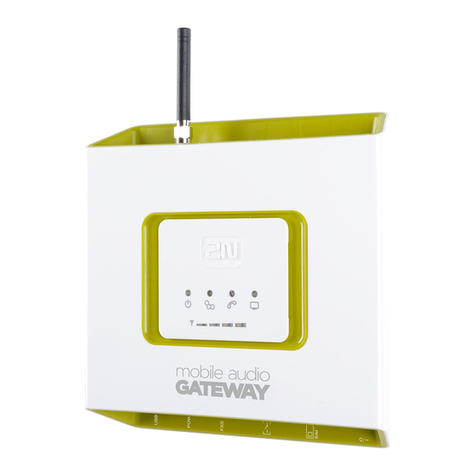
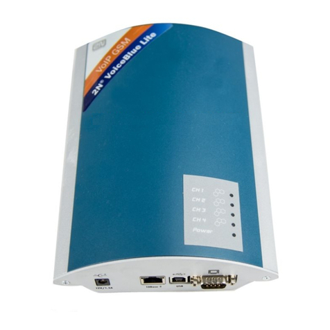
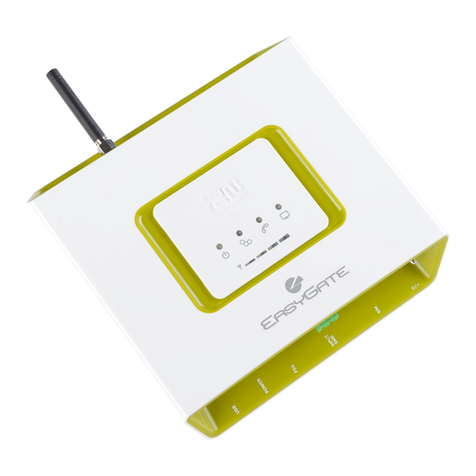
2N ATEUS 501106E User manual

ATEUS® - DIAL-THRU GSM GATEWAY
Ordering Nr. 501106E
Ordering Nr. 501107E
User Manual
Version of manual: 1.1
V
ersion of firmware: 2.51


1
Dear customer,
Let us congratulate you on purchasing our ATEUS® - DIAL-THRU GSM GATEWAY.
During the development and production of this product, care was taken to maximise
its value, quality and reliability. We hope you will use the GSM Gateway to it full
potential with long lasting benefits.
! Important !
• The manufacturer currently updates the firmware integrated into this product. The ISP
technology (In System Programming) allows you to load the latest software versions via the
RS232 port on the unit from any computer. For the latest software version including all
accessories please refer to www.2n.cz,for instructions please see the “Control Software
Upgrade” section of this manual. We recommend you use the latest software version in
order to guarantee the latest functionality of this GSM Gateway..
• To program your GSM Gateway parameters using a PC you need the “GSM – Program
Software“. For the most recent version of this programming tool please refer to www.2n.cz.
• You will find the latest version of this Manual in the popular .PDF format on www.2n.cz also.
You are recommended to view the latest version in order to find explanations of new
functions necessary for any software updates.
• Please read this Manual carefully before installing and using this product for the first time.
The manufacturer is not liable for any loss incurred by the user as a result of incorrect usage
of the unit. Our warranty terms and conditions do not cover damage caused by rough
handling, improper storage, or exceeding the specified technical parameters.
• This Manual is quite comprehensive and includes sections that are not applicable for the
basic installation of the unit, other section also include information that may not be
applicable to your particular. Please note your gateway model number and refer to these
sections only.
• Preliminary information on functions that will be available in later software releases will have
a light-grey background or in grey font.

2
History
Version What has changed or new in this version
1.0
• Common information taken from the ATEUS® - GSM GATEWAY COMPACT
2000 manual, version 10.0
• New parameters: 701 to 706
• Call Sorting Table expanded to 250 records, resulting in following changes:
• Intelligent Incoming Call Routing Table reduced to 50 records
• Service buffer disabled
1.1 • New model 501107 with GPRS
• New values of par. 5003 added. You can specify what to do, if GSM or PSTN network
are out of order, or if GSM line is occupied by data connection.

3
Checklist
Packaging list, please check the contents of your unit:
Item Quantity Notes
GSM Gateway - model corresponding to the order no.,
refer to the type label on the GSM Gateway backside 1
Mains (A.C. power supply) cord 1 1)
Telephone line cord 2
Serial cable 1
Antenna 1
Holder (for fixing to the wall) 1
Rawlplugs 2
Screws 2
This manual 1
Warranty Certificate 1
Software on CD-ROM • GSM program
• SMS program
• Driver for PC

4
Contents
1. Introduction............................................................................................6
1.1. PURPOSE.......................................................................................................................... 6
1.2. HOW TO SAVE GSM CALL COSTS.......................................................................................6
1.3. OTHER ADVANTAGES AND APPLICATIONS ............................................................................6
1.4. MAIN FEATURES ................................................................................................................7
2. Basic Installation Instructions ................................................................8
2.1. PROPER LOCATION ............................................................................................................8
2.2. TELEPHONE AND PSTN LINE CONNECTION .........................................................................9
2.3. EXTERNAL ANTENNA CONNECTION....................................................................................11
2.4. SIM CARD SET-UP AND INSTALLATION............................................................................... 11
2.5. POWER SUPPLY CONNECTION ..........................................................................................12
2.6. FUNCTIONAL VERIFICATION ...............................................................................................12
2.7. LED INDICATORS............................................................................................................. 13
3. User Manual – Description of Basic (Voice) Function............................13
3.1. OUTGOING CALL TO GSM ................................................................................................13
3.2. OUTGOING CALL TO PSTN...............................................................................................16
3.3. INCOMING CALL ...............................................................................................................17
3.4. BEGIN AND END OF CONNECTION SIGNALLING .....................................................................18
3.5. POWER FAILURE ..............................................................................................................18
3.6. AUTOMATIC DIALLING ("BABY CALL") ..................................................................................18
3.7. INTELLIGENT INCOMING CALL ROUTING.............................................................................. 18
3.8. TELEPHONE LINE TONES, RINGING COURSE - SUMMARY ....................................................20
3.9. PIN/PUK CODE ENTERING ..............................................................................................21
3.10. NOTES ............................................................................................................................22
3.11. INSTRUCTIONS FOR USE FOR COMMON USERS...................................................................23
4. User Manual – Description of Data Functions........................................24
4.1. USE OF DATA MODE ........................................................................................................24
4.2. PC-BASED SMS RECEIVE/SEND ......................................................................................26
5. Installation Instructions for Advanced Users ........................................27
5.1. DESCRIPTION FOR GSM GATEWAY ................................................................................... 27
5.2. DESCRIPTION OF GSM GATEWAY PCB.............................................................................30
5.3. FUSE EXCHANGE .............................................................................................................32
5.4. LITHIUM BATTERY EXCHANGE ...........................................................................................32
6. Programming ........................................................................................33
6.1. HOW TO PROGRAM .......................................................................................................... 33
6.2. BEFORE PROGRAMMING...................................................................................................33
6.3. HANDSET-BASED PROGRAMMING...................................................................................... 34
6.4. PC - BASED PROGRAMMING VIA SERIAL INTERFACE............................................................37
6.5. REMOTE PROGRAMMING BY PC ........................................................................................ 38

5
7. Parameter Tables..................................................................................44
7.1. BASIC PARAMETERS ........................................................................................................44
7.2. PBX’S CO LINE INTERFACE PARAMETERS.........................................................................48
7.3. CALL SORTING TABLE ...................................................................................................... 50
7.4. INTELLIGENT INCOMING CALL ROUTING TABLE ................................................................... 56
7.5. PARAMETERS FOR "DIAL-THRU" MODEL .............................................................................57
7.6. SERVICE PARAMETERS ....................................................................................................58
8. Miscellaneous.......................................................................................60
8.1. TELEPHONE COST SAVING TIPS ........................................................................................60
8.2. TROUBLE SHOOTING ........................................................................................................ 61
8.3. LIST OF ABBREVIATIONS ................................................................................................... 61
9. Technical Parameters ...........................................................................62

6
1. Introduction
1.1. Purpose
• ATEUS ®- DIAL-THRU GSM GATEWAY operates on single analog line between PSTN and
PBX (or a telephone set, coin-operated automatic machines, etc.). It allows its users to make
calls via the cheaper way, automatically switching between PSTN and GSM network.
• The voice mode, i.e. an outgoing or incoming call, is the basic function of the GSM Gateway.
The Gateway is equipped with all functions necessary for this purpose and offers ease of
use in this mode.
• Moreover, the GSM Gateway provides (in connection with a PC) data mode and SMS
receive/send mode too. These additional functions increase the utility value of the product.
• You need no additional equipment (mains adapter, external GSM telephone) to run the GSM
Gateway. The installation is so easy that even a non-professional can install it. All
programmable parameters are set at optimum values by default. You need only to fill in the
Call Sorting Table for correct outgoing calls routing. Once you have connected the telephone
line, antenna, power supply and your SIM card, you can start making calls without hesitation.
1.2. How to Save GSM Call Costs
• By connecting a GSM Gateway between your PBX or phone and PSTN you can make direct
calls into a mobile network. This saves PSTN – GSM connection costs. You need to fill in the
Call Sorting Table to set which prefixes will be redirected to GSM.
• Mobile telephone calls made by your colleagues from outside to your headquarters will be
cheaper too, if they will call to GSM number of your gateway.
• With the GSM Gateway you can use the most convenient tariff rate of your GSM operator,
because calls of all your GSM Gateway users will be billed together.
• If you use an answering and recording machine – a GSM service, you may pay for retrieving
messages. If you connect an answering machine of your own to the GSM Gateway, you pay
nothing for the retrieval.
• With the GSM Gateway you can eliminate selected numbers. You won’t pay for a call that is
disabled.
1.3. Other Advantages and Applications
• You can establish a telephone connection even where there are no fixed telephone lines
available (exhibitions, fairs, conferences, chalets...).
• You are not exposed to the high-frequency electromagnetic field as with a mobile telephone.
• You can also attach a coin-telephone to the GSM Gateway, as it is able to send tariff pulses.
You can assess the price for call connections yourself (with profit).

7
1.4. Main Features
• DTMF dialling
• Pulse dialling
• Operates on PBX CO line, between PBX and PSTN
• Operates with answering machine or telephone, between this device and PSTN
• GSM module SIEMENS TC35i, 900 and 1800 MHz band for 501106E
• GSM module SIEMENS MC35i, 900 and 1800 MHz band for 501107E
• High quality voltage protection at line interfaces
• No external mobile phone needed
• An easy installation
• Call sorting table – call routing to PSTN, GSM
• Barring possibility for selected calls
• Intelligent end of dialling recognition – faster connection
• Intelligent Incoming GSM Call Routing
• Tariff pulses: passed thru from PSTN, generated by the pseudo – tariff transmitter during GSM calls
• Begin & end of call signalling: passed thru from PSTN, generated during GSM calls
• Serial port RS-232C – for connecting to any PC
• SMS messages can be received & transmitted by PC
• Data mode – can be used as a modem with any PC
• Programming by phone (limited)
• Programming by PC
• Remote programming by PC

8
2. Basic Installation Instructions
This chapter describes the basic connection of the GSM Gateway that can be made in a few
minutes. All you have to do is to connect an antenna, the power supply cable and telephone
lines, insert your SIM card and the GSM Gateway is ready to work.
2.1. Proper Location
• The ATEUS ®- DIAL-THRU GSM GATEWAY is a transmitter in principle. You must comply
with the local regulations and laws in your country pertinent to usage of mobile phones and
transmitters!
• The ATEUS ®- DIAL-THRU GSM GATEWAY is designed for vertical mounting. For the
required working position see Fig.1.
• The GSM Gateway may be operated in a position other than vertical (on a desk, e.g.) for a
short time only – for quick maintenance testing, for example.
• For the acceptable range of operating temperature and humidity refer to the “Technical
Parameters”.
• The GSM Gateway may not be operated at places
exposed to direct solar or heat radiation.
• Exceeding the acceptable operating temperature does
not have an immediate impact on the GSM Gateway
function, but may result in accelerated ageing (of
batteries in particular!) and lower reliability.
• The GSM Gateway is designed for indoor use. It must
not be exposed to rain, water, condensed moisture, fog,
etc.
• The GSM Gateway must not be exposed to corrosive
gas, fumes of acids or solvents, etc., or corrosive liquids,
during cover cleaning, for example.
• The GSM Gateway is not intended for use in high-
vibration locations such as means of transport, machine
rooms, etc.
• The GSM Gateway should be located with respect to the
GSM signal quality.
• A free space should be left over and under the GSM
Gateway for cables and flowing air that removes heat
produced during the operation.
Fig. 1.: GSM Gateway Working Position

9
2.2. Telephone and PSTN Line Connection
2.2.1. Connection to PBX
Connect the ATEUS ®- DIAL-THRU GSM GATEWAY to external (C.O.) line of your PBX
and to PSTN line socket, as shown on picture. If your PBX has more PSTN lines, make sure
that outgoing calls to GSM will go out through this one or use more GSM gateways.
Fig. 2.: Connection to PBX
C.O. line preferred by PBX fo
r
outgoing calls

10
2.2.2. Connection to Telephone Set (Answering Machine, Coin-Phone etc.)
Connect the ATEUS ®- DIAL-THRU GSM GATEWAY to PSTN line socket and to your
telephone set or some other terminal equipment. For convenience, you can add “ATEUS ® -
Ping pong” (intelligent double or triple branch made by 2N TELEKOMUNIKACE a.s., order
Nos. 831127, 831128, 831137, 831138) to interconnect several devices, such as a
telephone set and an answering machine; see Fig. 3.
Note: If you connect a coin- phone, be sure to program the transmission of tariff pulses and
pseudo tariff metering! Remember also that tariff pulses are not generated during PSTN
calls. They must be generated by PSTN.
Fig. 3.: Optional Connection of
More Terminal Equipment

11
2.3. External Antenna Connection
Connect an antenna or an external antenna cable into the FME connector. The antenna
location should have a good GSM signal. The antenna should be in the vertical position. For
antenna and cable parameters refer to the “Technical Parameters”. Tighten an antenna
connector gently by hand; do not use any tools!
2.4. SIM Card Set-up and Installation
2.4.1. Operator / SIM Card Selection
To perform this GSM Gateway function you need a SIM card of a GSM network operator,
using the 900 MHz or 1800 MHz band (depending on GSM gateway model).
The ATEUS ® - DIAL-THRU GSM GATEWAY works with 3V SIM cards. All SIM cards
except for the oldest ones meet this condition. If you are not sure, ask your GSM
operator about voltage of your old SIM card. If your SIM card is new or you are going to
buy a new one, you need not worry – your SIM card will be O.K.
2.4.2. PIN Entering Blocking (Optionally)
The GSM Gateway provides automatic PIN entering by default. You can disable PIN
entering on your SIM card (using a mobile telephone into which you insert your SIM card
for this purpose). If you do disable, you need not worry as to whether there is a PIN code
stored in your GSM Gateway memory. If you enable PIN entering, your GSM Gateway
will require a PIN code after the first power-on and if you enter the PIN correctly, the
GSM Gateway will store it in its memory and enter automatically in the future.
2.4.3. GSM Network Service Setting (Answering Machine, Call Forwarding)
Before the SIM card installation decide whether you will use the incoming call
forwarding service provided by GSM networks (call forwarding in the event of busy line,
absence, unavailability...). However, it is more convenient to disable all call forwarding
modes (the GSM operator’s answering machine, e.g.) and use an answering and
recording machine of your own. If you have more GSM Gateways with your PBX, you
can forward calls when one GSM Gateway is busy, etc.
2.4.4. Roaming Parameters Setting (Calling via Foreign GSM Networks)
The GSM Gateway disables roaming by default. It is usually convenient because most
people do not travel with the GSM Gateway and there is a risk with roaming in foreign
countries that, due to a failure in the local GSM network, you might get registered in
another network and pay much more for your calls. To enable roaming and set network
preferences, complete the list of GSM networks to be preferred using your mobile
telephone and then enable roaming while programming the GSM Gateway.
The registration of the GSM Gateway in a foreign GSM network is signalled by a special dial
tone (refer to the list of tones) and you have to dial numbers including international
prefixes that can be easily barred (refer to Programming, Call Sorting Table).
2.4.5. SIM Card Insertion in GSM Gateway
To install the SIM card, press the yellow button on the SIM holder using a suitable tool
(e.g. scissor) to make the drawer slide out. Pull out the drawer, insert the SIM card in it,
slide the drawer back and click into position.

12
2.5. Power Supply Connection
• Make sure that the voltage in your mains corresponds with the data on the product label.
• Make sure that the antenna has been connected. If you connect a power supply to the
equipment without the antenna, you might cause damage to the GSM module transmitter.
• Connect your power cord. After a while, the green indicator “AC Supply O.K.” should go on.
2.6. Functional verification
Recommendation: check GSM gateway functionality prior to connecting it to your PBX and
programming.
1. Connect GSM gateway to previously checked telephone set and PSTN line. Verify that this
telephone is switched to DTMF and its ringer is ON. It is better to check a SIM card too,
using a mobile phone. It is not necessary to fix GSM gateway to a wall for testing – it can lie
on flat surface as well. Excepting this, follow chapters 2.2 to 2.5 to connect all needed.
2. If the inserted SIM card requires a PIN, the red lamp “Enter PIN” will light up. In this case,
pick up the handset of connected a phone. You will hear a PIN tone .
Enter PIN as described in chapter 3.9.2 and hang up, the red “Enter PIN” lamp will go out.
3. The GSM gateway will register itself into the GSM network. First, the red “No GSM network”
lamp must go out. After a moment, the green “GSM ready” lamp will light up.
4. Pick up the phone; you will hear the dialling tone and the “Line ready” lamp will start
blinking. If it doesn’t, the phone or its connection is bad.
5. Now check for signal quality. Enter programming mode according to chapter 6.3.2, skipping step
No. 1 (this applies only in the case of connection to a PBX). Indication of GSM signal quality will
be turned on automatically. As more lamps are lit, signal quality is better. If at least one green
lamp is lit up, signal quality is excellent. Try to find a good place for the antenna. Keep the
antenna vertical and move it slowly – signal quality information is updated every three seconds.
Remember that a movement as small as 10 cm may have a considerable effect on signal
quality, as well as a position close to your body. The best way is to step aside after each
relocating of antenna. Hang up after positioning the antenna; do not program anything!
6. Make an outgoing call. Remember that all calls will be routed to GSM by the factory default.
If your GSM gateway is not used first time and the Call Sorting Table is not empty, choose a
number, which will be routed to GSM. Call your colleagues mobile e.g. and verify that you
hear each other well. In the case of a completely new pre-paid SIM card, one outgoing call is
necessary for SIM card activation. Until it is activated an incoming call cannot be received!
Make an incoming call now. Call the GSM gateway from some mobile; the phone should
ring.
7. To check PSTN interface, use an incoming call. Ask somebody to call from some phone to
PSTN line which is connected to your GSM gateway; the phone should ring. Pick it up and
verify, that you hear each other well.
8. The GSM gateway is now checked. You can now connect it to a C.O. line of the PBX. After
connection is completed, fill in the Call Sorting Table (for programming see chapter 6).
Check incoming call and outgoing calls again, both PSTN and GSM. This may, of course,
necessitate some programming or settings changes of the PBX. If everything is O.K., you
can go to programming, if it is required - see chapter 6.

13
2.7. LED Indicators
color, name Description of statuses
green
POWER
• lights = GSM module is powered
• blinking slowly = GSM module is not
powered (c. 6 seconds after switching on)
green
GSM
• lights = registered into native GSM
network
• blinking = registered into GSM, roaming
• dark = not registered into GSM sítě
yellow
LINE
• lights = GSM call (after connect)
• blinking slowly = PSTN call (after dialling)
• blinking fast = off hook before call,
making connection, incoming ringing
• dark = on-hook, or line error
yellow
DATA
• lights = GSM data connection established
• blinking = data exchange with PC, GSM
data connection not established
• dark = no activity on serial interface
red
ERROR
• lights = at least one from these errors:
o line error
o SIM is not present
o PIN is not entered
• blinking = GSM signal quality indication
• dark = no error
(ATTENTION! It doesn’t imply, that GSM
gateway is registered into GSM network!
3. User Manual – Description of Basic (Voice) Function
Users mostly use their PBXs and GSM Gateways intuitively, without reading any
instructions, or follow very simple instructions provided by an authorized person. The following
functional description is therefore intended for technicians, who follow the instructions
(depending on the PBX set-up) and solve any operational problems.
3.1. Outgoing Call to GSM
3.1.1. Picking Up the Line
The PBX picks up a line the moment a subscriber picks up his or her handset and dials a
number (or prefix) that is routed outside.
Note: If the GSM Gateway is busy, the PBX can either give the caller the busy tone
or choose another connection (PSTN, or there may be more GSM
Gateways with one PBX).

14
3.1.2. GSM Gateway Ready Signalling
The GSM Gateway registers the off-hook (current inflow). Immediately and then, if
everything is O.K., starts sending its usual dialling tone . Now the subscriber can
dial the number.
Notes:
• If GSM gateway needs PIN, special tone is transmitted. See chapter 3.9. Until the
correct PIN is entered, GSM gateway will not allow any outgoing call. Only an
incoming call from PSTN is allowed.
• In some cases, PBX operates as a repeater. Subscriber will dial whole number, then
PBX repeats it to PSTN line. In this case, subscriber will not hear dialling tone from
GSM gateway.
• As far as pulse dialling is selected, DTMF dialling can be used to enter programming
mode and program GSM gateway by phone. In case of any other DTMF dialling, GSM
gateway will answer by busy tone.
• If one network is not accessible, an outgoing call to second one is still possible. User
will hear normal dialling tone, but dialling may cause a busy tone - if inaccessible
network is required. If enabled by par. 5003, the call to inaccessible network can be
rerouted to the second one.
GSM network is not accessible in these instances:
o GSM module in use (data mode)
o No SIM
o GSM network failure, no antenna etc.
PSTN network is not accessible in the case of PSTN line failure - no current.
• In this moment, GSM gateway also picks up the PSTN line. This help to avoid a
conflict with incoming call from PSTN.
3.1.3. Dialling Receive
The GSM Gateway is ready to receive pulse or tone dialling (according to the set-up). As
soon as the subscriber starts dialling a number, the GSM Gateway mutes the dialling
tone (as with public telephone exchanges). The user must dial digits in no more
than 6 second intervals; otherwise the number is regarded as complete and sent to the
GSM network (this timeout is programmable).
Notes:
• If pulse dialling is selected, and the call is routed to PSTN, dialled number is
transformed to DTMF.
• If pulse dialling is selected, DTMF can be still used for programming.
• Some PBXs analyse the whole number first and then transmit the dialling into the CO line
(GSM Gateway). Here, the signalling type and the timeout depend on the PBX set-up!
3.1.4. Dialling End Recognition
The GSM Gateway itself can recognize the end of some numbers according to their
length. Moreover, you can set your GSM Gateway in such a way that the GSM Gateway
accepts the ‘*‘ or ‘#‘ (for tone dialling only) symbols as the end of dialling. Otherwise, it
waits 6 seconds after the subscriber stops dialling (the timeout is programmable). Then,
the subscriber can hear a short tone signalling the dialling end.
Note: If the caller goes on dialling, the GSM Gateway will not accept the extra digits!

15
3.1.5. Call Routing
According to a record found in the Call Sorting Table, call is routed to GSM or PSTN
network or bared. If the required network is not accessible, GSM gateway starts to send
busy tone or tries to reroute the call to second network if it is enabled by par. 5003.
Otherwise, the GSM Gateway transmits the received number into the right network.
Description for the case of GSM follows.
3.1.6. Connection Making and Establishing
In this moment, GSM gateway sends whole received number (or a number changed by
“take away” and “append” parameters) to the GSM network. Next, GSM network is
making a connection, and it takes typically 8 seconds. During this time, the subscriber
hears a special "call progress" tone (differs by GSM gateway model and version of
software). Next, the subscriber usually hears the ringing tone or
another signal transmitted by the GSM network. The connection, however, is not
established and paid for until the called party answers the phone. The GSM network
signals this moment and the GSM Gateway can pass the information to the PBX. If this
type of signalling is used (exceptionally), the calling party can hear a click in the
earphone.
3.1.7. The Call
The call may be terminated forcibly if the GSM signal gets lost, for example, or in similar
situations.
During the call, GSM gateway keeps PSTN line off-hook. This is important because GSM
gateway is not able to serve incoming call from PSTN, till PBX line is busy by outgoing
GSM call. If somebody will call to you (via PSTN line), he or she will get busy tone from
public exchange.
3.1.8. Tariff pulses
During outgoing call to GSM, the GSM Gateway can transmit pseudo-tariff pulses,
according to the Call Sorting Table.
ATTENTION! If filled wrong, it may cause that these pulses will not be transmitted, or will
not show a true price of the call.
3.1.9. Connection Termination (End)
If the caller is the first to hang up, the GSM Gateway registers the on-hook immediately
(the current flow stops) and terminates the connection. If the called party is the first to
hang up, the GSM Gateway gets the information from the GSM network and terminates
the connection. The GSM Gateway can pass the information to the PBX. The calling
party gets the busy tone (or another type depending on the set-up).
The time of call may be limited by parameter 158. 30 sec before this limit, GSM gateway
sends a warning tone. Last 10 sec a short beep repeats each second. A call interruption
follows, optionally busy tone and Power Down.
Note: With some calls, the called party‘s on-hook information is considerably delayed by
GSM network (30s, e.g.). The subscriber usually registers the on-hook earlier, hangs up,
and the GSM Gateway terminates the connection immediately.
3.1.10. Subscriber’s Disconnection (Power Down)
If a subscriber blocks the GSM Gateway by seizing the line without dialling a number, or
fails to hang up after the call, he or she will get the busy tone first and
then is disconnected (Power Down status).

16
3.2. Outgoing Call to PSTN
Till call routing, GSM gateway behaviour is the same as during GSM call. See chapter 3.1.1 to
3.1.4 for its description.
3.2.5. Call Routing
According to a record found in the Call Sorting Table, call is routed to GSM or PSTN
network or bared. If the required network is not accessible, GSM gateway starts to send
busy tone or tries to reroute the call to second network if it is enabled by par. 5003.
Otherwise, the GSM Gateway transmits the received number into the right network.
Description for the case of PSTN follows.
3.2.6. Connection Making and Establishing
Remember that the PSTN line is already off hook (see chapter 3.1.2, last note). In this
moment, GSM gateway checks how long is PSTN line off hook. If parameter 701 is over,
GSM gateway hangs up for a moment, using parameter 702. (This happens when a
dialling was very slow.) Next, whole number is repeated to the PSTN network (or a
number changed by “take away” and “append” parameters). DTMF is used always, even
if pulse dialling was received. Next, PSTN network is making a connection. During this
time, the subscriber may hear tones from PSTN. Next, the subscriber usually hears the
ringing tone or another signal transmitted by PSTN network.
3.2.7. The Call
During the PSTN call, incoming calls from GSM network are refused. (This is important
because GSM gateway is not able to serve two calls at a time. Without refuse, calling
party hears ringing, but it is not possible to ring to PBX.)
3.2.8. Tariff pulses
During the outgoing call to PSTN, tariff pulses, if present, are passed from PSTN to PBX.
Pseudo-tariff parameters in the Call Sorting Table are ignored.
3.2.9. Connection Termination (End)
GSM Gateway registers the on-hook (the current flow stops) and switches to its default
state. It is important to secure that PBX will always hang up the line. The time of PSTN
call is not limited by parameter 158.
3.2.10. Subscriber’s Disconnection (Power Down)
If a subscriber blocks the GSM Gateway by seizing the line without dialling a number, or
fails to hang up after the call, he or she will get the busy tone first and
then is disconnected (Power Down status).

17
3.3. Incoming Call
3.3.1. GSM Gateway Ringing, Extension Dialling, Extension Ringing and Connection
Establishing
When the GSM Gateway receives a command from the GSM network and, if available,
the CLIP information, it starts ringing (i.e. generating the ringing voltage – whose timing is
programmable) into the PBX. The PBX registers the ringing and then, one of the
following situations may occur:
3.3.1.1 PBX without DISA = Selected Extension Ringing
In this case, the selected extension (or several extensions at the same time or
sequentially according to the PBX set-up) starts ringing and the calling subscriber will
not pay for the call until the ringing extension answers.
3.3.1.2 PBX with DISA, Intelligent Routing Off
In this case, the PBX answers and starts reproducing the so-called DISA message.
The GSM Gateway establishes connection immediately in order that the caller can
hear the message and dial the required extension.
3.3.1.3 PBX with DISA, Intelligent Routing On, and CLIP Present and Known
(Only for GSM calls. GSM gateway cannot receive CLIP from PSTN line.)
In this case, the PBX also answers and starts reproducing the DISA message. The
GSM Gateway, however, has found the caller’s number in its Intelligent Incoming Call
Routing Table and thus knows the extension to be called. Therefore, the GSM Gateway
does not establish connection immediately, but serves the DISA function (waits and dials
the extension number). Then, it establishes the connection and the calling subscriber can
hear the ringing tone and the called subscriber.
3.3.1.4 PBX with DISA, Intelligent Routing On, but CLIP Absent or Unknown
In this case, the PBX also answers and starts reproducing the DISA message. The GSM
Gateway, however, has not found the caller’s number in its Intelligent Incoming Call
Routing Table (or has not received the CLIP). Then it can (according to its set-up) either
work as described in 3.3.1.2, or as described in 3.3.1.3, plus dial the operator’s number.
3.3.2. Call
With incoming calls, the GSM Gateway waits until the call is terminated, which situation is
the same as with an outgoing call.
Another differences between GSM and PSTN calls:
3.3.2.1 GSM incoming call
GSM call may be terminated forcibly if the GSM signal gets lost, for example, or in similar
situations.
During the GSM call, GSM gateway keeps PSTN line off-hook. This is important because
GSM gateway is not able to serve incoming call from PSTN, till PBX line is busy by GSM
call. If somebody will call to you (via PSTN line), he or she will get busy tone from public
exchange.
3.3.2.2 PSTN incoming call
During the PSTN call, incoming calls from GSM network are refused. (This is important
because GSM gateway is not able to serve two calls at a time. Without refuse, calling
party hears ringing, but it is not possible to ring to PBX.)
3.3.3. Connection Termination (End)
For GSM call termination, see chapter 3.1.9
For PSTN call termination, see chapter 3.2.9

18
3.3.4. Subscriber Disconnection (Power Down)
If a subscriber blocks the GSM Gateway unnecessarily by not hanging up after the call, he or
she will get the busy tone first and then is disconnected (Power Down status).
3.4. Begin and end of connection signalling
Signalling by a current break or polarity change (see parameters 231 to 234) works
differently in a case of GSM and PSTN call:
GSM call: signals may be generated by GSM gateway, according to parameters 231 to 234.
PSTN call: signals may be only passed from PSTN network.
NOTES:
• This difference may cause some problems, be careful when using this function.
• GSM gateway is physically switching PSTN line to PBX line during PSTN calls. To
avoid possible polarity change in the moment of switching, GSM gateway checks
PSTN line polarity after power on and optionally reverse polarity of PBX line to match
polarity of PSTN line. When connecting to other PSTN line, always switch GSM
Gateway off. Otherwise, polarity change may cause some problems, and also audible
clicks are louder.
3.5. Power failure
During power failure (or if power cord is disconnected), PBX and PSTN connectors are
interconnected. It means that all calls are realized via PSTN, and GSM gateway cannot bare
any calls, of course.
3.6. Automatic dialling ("baby call")
Outgoing calls are described in chapters 3.1 and 3.2 on the assumption that automatic
dialling is off (default). If parameter "Number for automatic dialling" is filled, this function is
automatically switched on and GSM gateway operates as follows:
As soon as line is picked up, GSM gateway awaits dialling for limited time, defined by
parameter "time for automatic dialling". If user starts dialling within this time, GSM gateway
operates normally, as described in chapter 3.1. Otherwise, if this time is out, GSM gateway
automatically makes a call to programmed number. “Baby call” is always routed via GSM
network. In case of inaccessible GSM network can be the call routed via PSTN network if it is
enabled by par. 5003.
Note: It is assumed, that GSM gateway is connected to phone. If GSM gateway is
connected to PBX, applicability of automatic dialling function depends on PBX's settings.
3.7. Intelligent Incoming Call Routing
This function can be applied to incoming calls from GSM only (if enabled). If CLIP (number
of calling subscriber) is found in Intelligent Incoming Call Routing Table (see chapter 7.4.), GSM
gateway will call a dedicated extension according to this table. If GSM gateway is connected to
external (C.O.) line of PBX, DISA function must be used in PBX to serve it. This function is
operating automatically, as described in previous chapter 3.3.
This manual suits for next models
1
Table of contents
Other 2N Gateway manuals
Popular Gateway manuals by other brands

RTA
RTA 460ECPS-N2EW Product user guide

Sangoma
Sangoma Vega 60G quick start guide

Hypercom
Hypercom IN-tact 1101 Technical specifications

Dension
Dension Lite BT user manual

ZyXEL Communications
ZyXEL Communications Prestige 2302R Series user guide

HMS Networks
HMS Networks Intesis INMBSMEB 0100 Series Installation sheet

NETGEAR
NETGEAR CG3100 user manual

Belden
Belden GRASS VALLEY IPG-3901 Guide to installation and operation

Eaton
Eaton EU5C-SWD-EIP-MODTCP manual

ADTRAN
ADTRAN 8612 quick start guide

DEUTSCHMANN AUTOMATION
DEUTSCHMANN AUTOMATION UNIGATE EL-DeviceNet instruction manual

Yolink
Yolink YS1603-UC Installation manual & users guide