manuals.online logo
Brands
  1. Home
  2. •
  3. Brands
  4. •
  5. 3One data
  6. •
  7. Switch
  8. •
  9. 3One data TNS5000D Series User manual

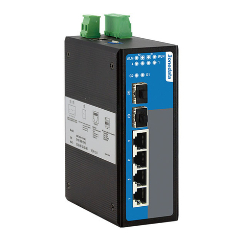
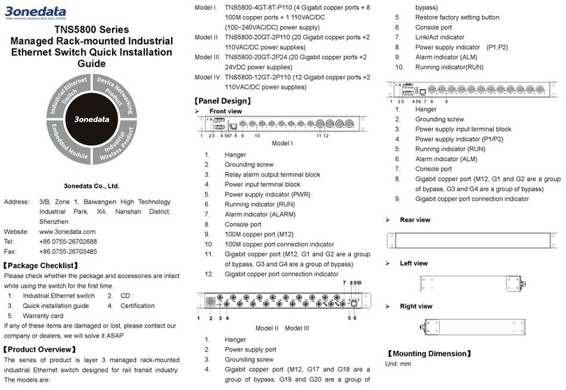
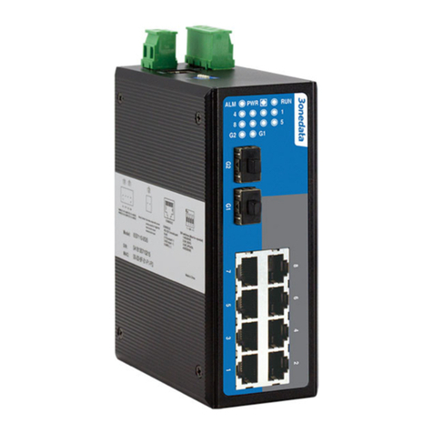
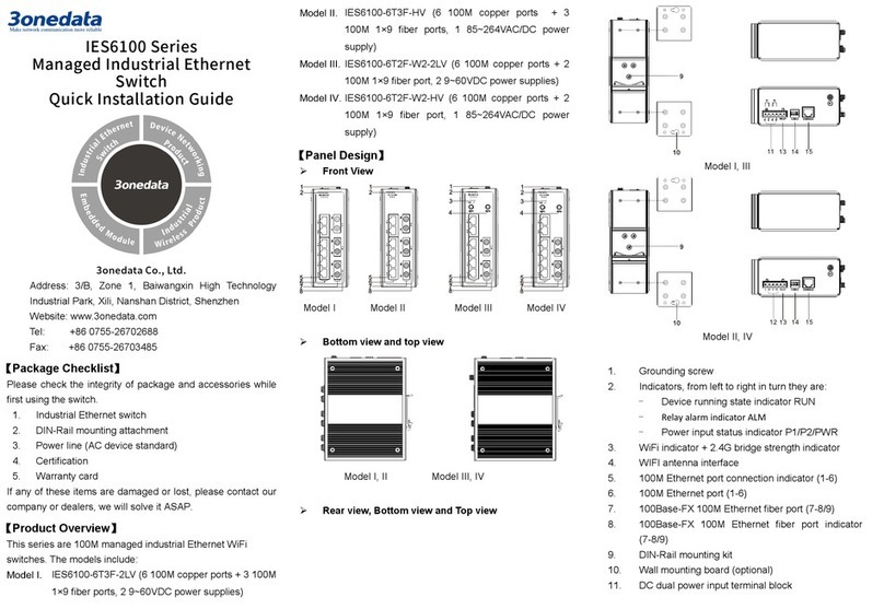
3One data TNS5000D Series User manual

TNS5000D Series
Unmanaged Wall-mounted Industrial
Ethernet Switch
Quick Installation Guide
3onedata Co., Ltd.
Address: 3/B, Zone 1, Baiwangxin High Technology
Industrial Park, Xili, Nanshan District, Shenzhen
Website: www.3onedata.com
Tel: +86 0755-26702688
Fax: +86 0755-26703485
【Package Checklist】
Please check the integrity of package and accessories while
first using the switch.
1.
Industrial Ethernet switch
2
Quick installation guide
If any of these items are damaged or lost, please contact our
company or dealers, we will solve it ASAP.
【Product Overview】
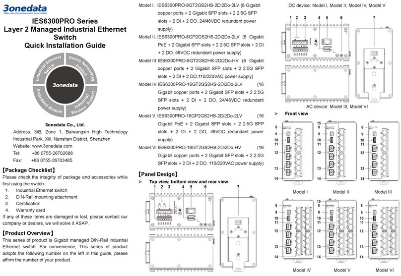
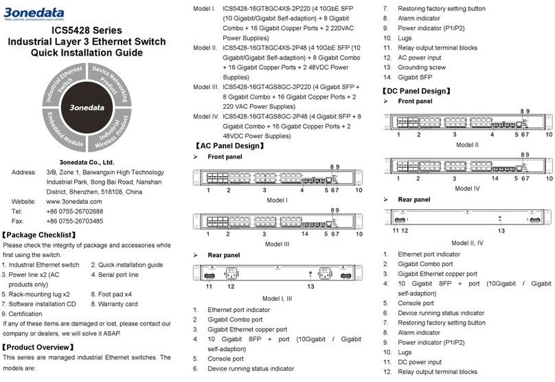
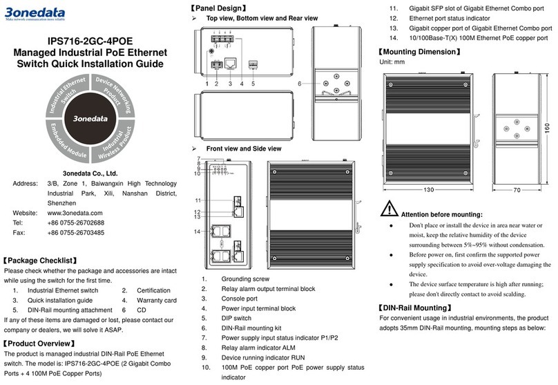
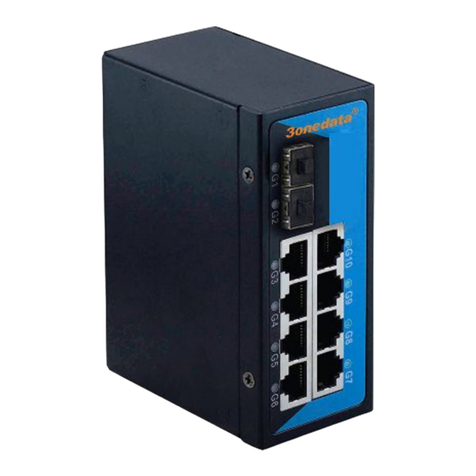
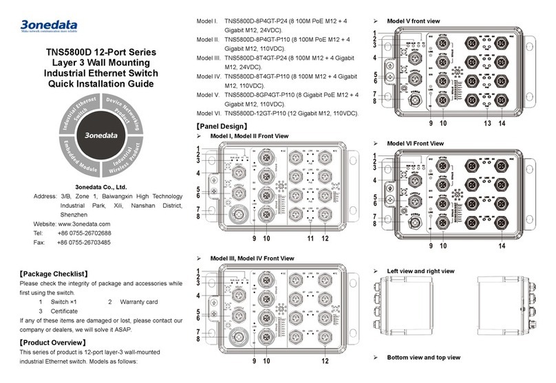
This series of product is 8-port 100M layer-2 unmanaged
wall-mounted industrial Ethernet switch designed for rail
transit. Models as follows:
Model I. TNS5000D-8T-P110(8 100M M12 + 1 110VDC
power supply input)
Model II. TNS5000D-8T-P24(8 100M M12 + 1 24VDC power
supply input)
【Panel Design】
Front view
Bottom view
Right view
1. Power input status indicator PWR
2. Device running state indicator RUN
3. Relay alarm state indicator ALM (reserved)
4. Grounding screw
5. SERVICE Debug Serial Port
6. Power and relay (reserved) access terminal X1
7. 10/100Base-T(X) 100M copper port (X11-X18)
8. 100M copper port connection indicator (X11-X18)
Lug【Mounting Dimension】
Unit: mm
Notice Before Mounting:
Don't place or install the device in area near water or
moist, keep the relative humidity of the device
surrounding between 5%~95% without condensation.
Before power on, first confirm the supported power
supply specification to avoid over-voltage damaging the
device.
The device surface temperature is high after running;
please don't directly contact to avoid scalding.
【Wall-mounted Device Mounting】
On the wall of device mounting, place the device on
the wall for reference or refer to the mounting
dimension to mark two screw positions.
through h ole
Nail screws on the wall and keep 7mm interspace
reserved.
Hang the device on 4 screws and slide downward,
then tighten the screw. Mounting ends.
【Wall-mounted Device Disassembling】
Power off the device.
Unscrew the screw on the wall about 7mm.
Lift the device upward slightly; take out the device,
disassembling ends.
Notice before power on:
Power ON operation: First insert the power supply
terminal block into the device power supply interface,
then plug the power supply plug contact and power on.
Power OFF operation: First, remove the power plug,
then remove the wiring section of terminal block. Please
pay attention to the above operation sequence.
【Power Supply Connection】
This series device provides 1 DC power input,
and the interface adopts M12 A-Coded 4-Pin
connector (male), in which the power supply
occupies two pins V- and V+, which can be
connected with M12 A-Coded 4-Pin slot (female).
Model I power input range: 110VDC(66~154VDC);
Model II power input range: 24VDC (9~36VDC).
The pin definitions of M12 (male) are shown as follows:
Pin
Definition
V+ V- RELAY1 RELAY2
Description
Positive
power
input
Negativ
e power
input
Reserved Reserved
【Service Port Connection】
This series of device provides a program
debugging port of M12 D-Coded 4-Pin(Female)
connector, which can be connected with PC for CLI
command management of the device. The interface adopts
M12 D-Coded 4-Pin slot (male).
The pin definitions of M12 are shown as follows:
Pin
Definition
TX
RX
NC
GND
Description
RS
-
232 send
signal
RS-232
receive
signal
Reserved
Ground
Note: Service port is only for debugging by our technicians.
【Communication Interface Connection】
This device provides 8 10/100Base-T(X) interfaces,
the interface type is M12 D-Coded 4-Pin slot
(female). The definitions of M12 pin are as follows:
【Checking LED Indicator】
The series of devices provide LED indicators to monitor its
operating status, which has simplified the overall
troubleshooting process. The function of each LED is
described in the table below:
LED
Indicate
Description
PWR (X1) ON PWR is connected and running
normally
OFF
PWR is disconnected and
running abnormally
RUN
ON The device is powering on or the
device is abnormal.
OFF The device is powered off or the
device is abnormal.
Blinking
Blinking 1 time per second,
system is running normally
Link
(X11-X18)
ON Ethernet port has established a
valid network connection
Blinking
Ethernet port is in an active
network status
OFF
Ethernet port has not
established valid network
connection
【Specification】
Panel
Power supply interface M12(Male), 4-Pin A-Coded, the
power supply occupies two pins
V- and V+
Relay interface
Reserved
M12 (Male), 4-Pin A-Coded,
relay occupies two pins,
RELAY1 and RELAY2
100M Ethernet port 10/100Base-T(X),
M12(Female), 4-Pin D-Coded,
Automatic Flow Control,
Full/half Duplex Mode,
MDI/MDI-X Autotunning
Service debugging port
M12 (Female)
,
4-PinD-Coded
Indicator
Power indicator, running
indicator, alarm indicator
(reserved), interface indicator
Switch Property
Backplane bandwidth
7.6G
Packet buffer size
1Mbit
MAC Address Table
8K
Power Supply
Pin No. Definition Description
1 TD+ Positive send data of
100M Ethernet
2 RD+ Positive receive data of
100M Ethernet
3 TD- Negative send data of
100M Ethernet
4 RD- Negative receive data
of 100M Ethernet
Input power supply
M12 A-Coded 4-Pin (male)
connector
Model I: 110VDC
(66~154VDC)
Model II: 24VDC
(9~36VDC)
Power Consumption
No-load
2.1W@24VDC
Full-load
3.8W@24VDC
Working Environment
Working temperature -40 ~ 75℃, in which working
≥10 minutes at 85
℃
Storage temperature
-40~85℃
Working humidity
5%
~
95% (no condensation)
Protection grade
IP65(metal shell)

Other 3One data Switch manuals

3One data ICS6420 Series User manual

3One data

3One data ICS6420 Series User manual

3One data IPS3110 Series User manual

3One data

3One data IPS3110 Series User manual

3One data IES215 Series User manual

3One data

3One data IES215 Series User manual

3One data TNS5800 Series User manual

3One data

3One data TNS5800 Series User manual

3One data IES6300 Series User manual

3One data

3One data IES6300 Series User manual

3One data TNS5800D User manual

3One data

3One data TNS5800D User manual

3One data IPS215 Series User manual

3One data

3One data IPS215 Series User manual

3One data PS5010G-2GS-8PoE User manual

3One data

3One data PS5010G-2GS-8PoE User manual

3One data IES5028G Series User manual

3One data

3One data IES5028G Series User manual

3One data ICS5000-E24GP4GS User manual

3One data

3One data ICS5000-E24GP4GS User manual

3One data IPS7110-2GC-8POE User manual

3One data

3One data IPS7110-2GC-8POE User manual

3One data IES716-2GS User manual

3One data

3One data IES716-2GS User manual
3One data IES2005-5T-P48 User manual

3One data

3One data IES2005-5T-P48 User manual

3One data IES1024 Series User manual

3One data

3One data IES1024 Series User manual

3One data PS5026G-2GS-24PoE User manual

3One data

3One data PS5026G-2GS-24PoE User manual

3One data ICS6400-12GT12GS4XS User manual

3One data

3One data ICS6400-12GT12GS4XS User manual

3One data SW4485I User manual

3One data

3One data SW4485I User manual

3One data IPS7112G-4GS-8GPOE User manual

3One data

3One data IPS7112G-4GS-8GPOE User manual

3One data ICS5400 Series User manual

3One data

3One data ICS5400 Series User manual

3One data IES7110-2GS Series User manual
3One data

3One data IES7110-2GS Series User manual

3One data IES3000 Series User manual

3One data

3One data IES3000 Series User manual

3One data PS5026G-2GS-24PoE Operating and maintenance instructions

3One data

3One data PS5026G-2GS-24PoE Operating and maintenance instructions

3One data ES209G-1GF User manual

3One data

3One data ES209G-1GF User manual

3One data IES3016 Series User manual

3One data

3One data IES3016 Series User manual

Popular Switch manuals by other brands
Zte ZXR10 5900 Series Product description

Zte

Zte ZXR10 5900 Series Product description

Hawking CS164 user manual

Hawking

Hawking CS164 user manual

Escient ZONE LS102 installation guide

Escient

Escient ZONE LS102 installation guide

Moxa Technologies EDS-408A user manual

Moxa Technologies

Moxa Technologies EDS-408A user manual

TP-Link JetStream T1500-28PCT user guide

TP-Link

TP-Link JetStream T1500-28PCT user guide

Renesas Emulation Pod for M30240 Group MCUs... user manual

Renesas

Renesas Emulation Pod for M30240 Group MCUs... user manual

ADTRAN NetVanta 1638 Hardware installation guide

ADTRAN

ADTRAN NetVanta 1638 Hardware installation guide

Alloy POEFE8TV2 user manual

Alloy

Alloy POEFE8TV2 user manual

3Com Baseline 2226-PWR Plus user guide

3Com

3Com Baseline 2226-PWR Plus user guide

Extreme Networks 200 Series Installation and user guide

Extreme Networks

Extreme Networks 200 Series Installation and user guide

Leviton Decora L5614 Installation

Leviton

Leviton Decora L5614 Installation

HP V1810-48G Quick setup guide

HP

HP V1810-48G Quick setup guide

Longshine LCS-883R-SW2402 user manual

Longshine

Longshine LCS-883R-SW2402 user manual

Cisco 6500 - Catalyst Series 10 Gigabit EN Interface Module... Installation note

Cisco

Cisco 6500 - Catalyst Series 10 Gigabit EN Interface Module... Installation note

Wulian WL-SFB-S Series user manual

Wulian

Wulian WL-SFB-S Series user manual

Emulex Model 375 Quick install card

Emulex

Emulex Model 375 Quick install card

EUCHNER TQ2-1211SG024-5000 operating instructions

EUCHNER

EUCHNER TQ2-1211SG024-5000 operating instructions

TRENDnet TEG-S240TX - DATA SHEETS Specifications

TRENDnet

TRENDnet TEG-S240TX - DATA SHEETS Specifications

manuals.online logo
manuals.online logoBrands
  • About & Mission
  • Contact us
  • Privacy Policy
  • Terms and Conditions

Copyright 2025 Manuals.Online. All Rights Reserved.