manuals.online logo
Brands
  1. Home
  2. •
  3. Brands
  4. •
  5. 3One data
  6. •
  7. Switch
  8. •
  9. 3One data IES2210 Series User manual

3One data IES2210 Series User manual

IES2210 Series
Unmanaged Industrial Ethernet
Switch Quick Installation Guide
3onedata Co., Ltd.
Address:
3/B, Zone 1, Baiwangxin High Technology
Industrial Park, Xili, Nanshan District,
Shenzhen
Website:
www.3onedata.com
Te l :
+86 0755-26702688
Fax:
+86 0755-26703485
【
Package Checklist
】
Please check whether the package and accessories are intact
while using the switch for the first time.
1.
Industrial Ethernet switch
2.
Certification
3.
DIN-Rail mounting attachment
4.
Warranty card
If any of these items are damaged or lost, please contact our
company or dealers, we will solve it ASAP.
【
Product Overview
】
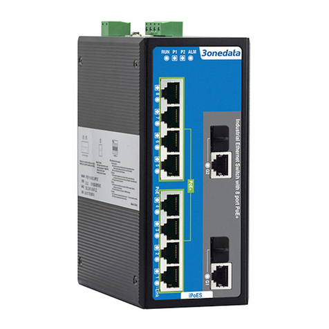
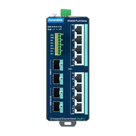
This series are unmanaged DIN-Rail industrial Ethernet
switches. Models as follows:
Model I. IES2210-8T2GC-2P48 (8 100M copper ports + 2
Gigabit Combo ports + 2 48VDC power supplies)
Model II. IES2210-8T2GC-P220 (8 100M copper ports +2
Gigabit Combo ports +1 220VAC power supply)
Model III. IES2210-4T2GC-2P48 (4 100M copper ports + 2
Gigabit Combo ports + 2 48VDC power supplies)
Model IV. IES2210-4T2GC-P220 (4 100M copper ports + 2
Gigabit Combo ports + 1 220VAC power supply)
Model V. IES2210-8P2GC-2P24-120W (8 100M POE
copper ports +2 Gigabit Combo ports +2 24VDC
power supplies +120W POE power)
Model VI. IES2210-8P2GC-2P48-120W (8 100M POE
copper ports +2 Gigabit Combo ports +2 48VDC
power supplies +120W POE power)
Model VII. IES2210-8P2GC-2P48-240W (8 100M POE
copper ports + 2 Gigabit Combo ports + 2 48VDC
power supplies +240W POE power)
Model VIII. IES2210-4P2GC-2P24-60W (4 100M POE copper
ports +2 Gigabit Combo ports +2 24VDC power
supplies + 60W POE power)
Model IX. IES2210-4P2GC-2P24-120W (4 100M POE
copper ports + 2 Gigabit Combo ports +2 24VDC
power supplies + 120W POE power)
Model X. IES2210-4P2GC-2P48-120W (4 100M POE
copper ports +2 Gigabit Combo ports +2 48VDC
power supplies + 120W POE power)
【
AC Panel Design
】
Top view, Bottom view and Rear view
Side view
Model IV Model II
1. AC power input terminal block
2. Relay alarm output terminal block
3. DIP switch
4. Console port
5. Grounding screw
6. Wall-mounted location hole
7. DIN-Rail mounting kit
8. Device running indicator RUN
9. Relay alarm indicator ALM
10. Power input status indicator PWR
11. 100M copper port
12. Ethernet port indicator
13. Combo port
【
DC Panel Design
】
Top view, Bottom view and Rear view
Side view
Model III Model I
Model VIII, IX,X Model V, VI,VII
1. DC power input terminal block
2. Relay alarm output terminal block
3. DIP switch
4. Console port
5. Grounding screw
6. Wall-mounted location hole
7. DIN-Rail mounting kit
8. Device running indicator RUN
9. Relay alarm indicator ALM
10. Power input status indicator PWR
11. 100M copper port
12. Ethernet port indicator
13. Combo port
14. POE indicator
【
Mounting Dimension
】
Unit: mm
Attention before mounting:
Don't place or install the device in area near water or
moist, keep the relative humidity of the device
surrounding between 5%~95% without condensation.
Before power on, first confirm the supported power
supply specification to avoid over-voltage damaging the
device.
The device surface temperature is high after running;
please don't directly contact to avoid scalding.
【
DIN-Rail Mounting
】
The product adopts 35mm standard DIN-Rail mounting, which
is suitable for most of the industrial scenes. Mounting steps as
below:
Check if the DIN-Rail mounting kit is installed firmly.Step 1
Insert the bottom of DIN-Rail mounting kit (one sideStep 2
with spring support) into DIN-Rail, and then insert
the top into DIN-Rail.
Tips:
Insert a little to the bottom, lift upward and then insert
to the top.
Check and confirm the product is firmly installed onStep 3
DIN-Rail, then mounting ends.
【Disassembling DIN-Rail】
Power off the device.Step 1
After lift the device upward slightly, first shift out theStep 2
top of DIN-Rail mounting kit, then shift out the
bottom of DIN-Rail, disassembling ends.
Attention before power on:
Power ON operation: first connect power line to the
connection terminal of device power supply, then power
on.
Power OFF operation: first unpin the power plug, then
remove the power line, please note the operation order
above.
【Power Supply Connection】
DC power supply 24VDC
This series of model V, model VIII, model
IX provide 6 pins 5.08mm pitch input
terminal blocks, including 4 pins power
supply terminal blocks on the left side. It
provides two independent DC power
supply systems of P1 and P2. The power supply is
anti-reverse connection.
Power input voltage: 24VDC
DC power supply 48VDC
This series of model I, model III, model VI
model VII and model X provide 6 pins
5.08mm pitch input terminal blocks,
including 4 pins power supply terminal
blocks on the left side. It provides two
independent DC power supply systems of P1 and P2. The
power supply is anti-reverse connection.
Power input voltage of model VI model VII and model X:
48VDC, power input voltage of model I and model III: 48VDC
(12~48VDC).
AC power supply 220VAC
This series of model II and model IV
support AC single power supply and
provide 6 pins 5.08mm pitch input
terminal blocks, including 4 pins power supply terminal blocks
on the left side.
Power input voltage: 220VAC (85~264VAC).
【
PoE Power Supply Pin Connection
】
PoE port is powered by the following pins.
Pin
1
2
3
6
Definition
V+
V+
V-
V-
【
Relay Connection
】
The device provides 6-pin 5.08mm pitch input terminal blocks,
including 2-pin relay terminal blocks on the right side. Relay
terminals are a pair of normally open contacts in device alarm
relay. They are open circuit in normal non alarm state, closed
when any alarm information occurs. For example: it's closed
and sends out alarm when power off. The switch supports 1
relay alarm information and network abnormal alarm output, it
can be connected to alerting lamp, alarm buzzer, or other
switching value collecting devices for timely warning operating
staffs when alarm information occurs.
【
DIP Switch Settings
】
This series provide 4 pins DIP switch for
function settings, where "ON" is enable valid
terminal. DIP switch definition as follows:
DIP
Definition
Operation
1 Flow control Set the DIP switch to ON, and
the device will enable flow
control
2 Port with the
specified
speed of 10M
Set the DIP switch to ON, and
the 100M copper port of the
device will be specified as 10M
DIP
Definition
Operation
copper port
3 Alarm Set the DIP switch to ON, and
the device will enable port alarm
4
Reserved
-
【
Checking LED Indicator
】
The function of each LED is described in the table as below:
LED
Status
Description
P1/P2/PWR
ON Power supply is connected
and running normally
OFF
Power supply is
disconnected and running
abnormally.
ALM
ON
Port link alarm
OFF
Port link without alarm
RUN
ON The device is powered on or
the device is abnormal.
OFF The device is powered off or
the device is abnormal.
Blinking
System is running well.
Link/ACT
(1-4/8, G1-G2)
ON Ethernet port connection is
active.
Blinking
Data transmitted
OFF Ethernet port connection is
inactive.
POE (1-4/8)
ON POE port supply electricity
for other devices normally
OFF POE is disabled or
disconnected
【
Specification
】
Panel
100M POE copper port
10/100 Base-T(X) RJ45,
automatic flow control, full/half
duplex mode, MDI/MDI-X
autotunning, POE port, the
output power consumption is
15W or 30W.
POE pins V+, V+, V-, V- are
corresponding to 1, 2, 3, 6.
Gigabit Combo port 10/100/1000Base-T(X) or
1000Base-X
Console port
Reserved
Alarm interface
6-pin 5.08mm pitch terminal
blocks, including 2-pin alarm
terminal blocks. It supports 1
relay alarm information output,
current load capacity is
1A@30VDC or 0.3A@125VAC
Indicator
Run indicator, interface
indicator power indicator, alarm
indicator, PoE indicator
Exchange attributes
Backplane bandwidth
7.6G
Packet buffer size
1Mbit
MAC table size
8K
Power supply
Input power supply
Power supply input voltage:
48VDC, 24VDC, 220VAC
Support DC dual power supply
redundancy, anti-reverse
connection
Access terminal
6-pin 5.08mm pitch terminal
blocks, including 4-pin power
supply terminal blocks
Consumption
No-load
≤4.9W@48VDC
Full-load
≤122.8W@48VDC
Environmental limits
Working temperature
-40~75
℃
Storage temperature
-40~85
℃
Working humidity
5%~95% (no condensation)
Protection grade
IP40 (metal shell)
1 8

This manual suits for next models

10

Other 3One data Switch manuals

3One data IPS7110 Series User manual

3One data

3One data IPS7110 Series User manual

3One data IPS7110-2GC-8POE User manual

3One data

3One data IPS7110-2GC-8POE User manual

3One data IES206G-2GS User manual

3One data

3One data IES206G-2GS User manual

3One data IPS7110-2GC-8POE User manual

3One data

3One data IPS7110-2GC-8POE User manual

3One data TNS5800 Series User manual

3One data

3One data TNS5800 Series User manual

3One data ICS5530-16GS8GC6XS-2P220 User manual

3One data

3One data ICS5530-16GS8GC6XS-2P220 User manual

3One data IES7116G-8GS Series User manual

3One data

3One data IES7116G-8GS Series User manual

3One data IES6100 Series User manual

3One data

3One data IES6100 Series User manual

3One data IES215-1GX-4G User manual

3One data

3One data IES215-1GX-4G User manual

3One data ICS5530 Series User manual

3One data

3One data ICS5530 Series User manual

3One data TNS5800 Series User manual

3One data

3One data TNS5800 Series User manual

3One data IES618 Series User manual

3One data

3One data IES618 Series User manual

3One data IES6316-8GT8GS-2P48 User manual

3One data

3One data IES6316-8GT8GS-2P48 User manual

3One data IPS215-4POE User manual

3One data

3One data IPS215-4POE User manual

3One data IES2100SL Series User manual

3One data

3One data IES2100SL Series User manual

3One data IPS7112G-4GS-8GPOE User manual

3One data

3One data IPS7112G-4GS-8GPOE User manual

3One data IES2010 Series User manual

3One data

3One data IES2010 Series User manual

3One data ICS5400 Series User manual

3One data

3One data ICS5400 Series User manual

3One data TNS5500D Series User manual

3One data

3One data TNS5500D Series User manual

3One data PS1005G-1GT-4POE Operating and maintenance instructions

3One data

3One data PS1005G-1GT-4POE Operating and maintenance instructions

3One data ICS5000-E24GP4GS User manual

3One data

3One data ICS5000-E24GP4GS User manual

3One data IES6300TSN-8GT2GS-2LV User manual

3One data

3One data IES6300TSN-8GT2GS-2LV User manual

3One data ICS6420 Series User manual

3One data

3One data ICS6420 Series User manual

3One data IES6300-8GHP2GS2HS-2P48-360W User manual
3One data

3One data IES6300-8GHP2GS2HS-2P48-360W User manual

Popular Switch manuals by other brands

GE "ExecutiveSeries"USB2.0 HO97863 instruction manual

GE

GE "ExecutiveSeries"USB2.0 HO97863 instruction manual

ViziT 19w 14.4v EU Operating	 instruction

ViziT

ViziT 19w 14.4v EU Operating instruction

Smartwares SH5-RPS-23A/CH quick start guide

Smartwares

Smartwares SH5-RPS-23A/CH quick start guide

Network Technologies KEEMUX-USBV-xU Installation & user guide

Network Technologies

Network Technologies KEEMUX-USBV-xU Installation & user guide

socomec ATyS 100A quick start

socomec

socomec ATyS 100A quick start

Panasonic AW-HS50N operating instructions

Panasonic

Panasonic AW-HS50N operating instructions

Raritan Dominion SX DSXA-16-DL Quick setup guide

Raritan

Raritan Dominion SX DSXA-16-DL Quick setup guide

ZyXEL Communications VDSL SWITCH VES-1616F-3X user guide

ZyXEL Communications

ZyXEL Communications VDSL SWITCH VES-1616F-3X user guide

NetComm 3G38WV-TS user guide

NetComm

NetComm 3G38WV-TS user guide

Campbell SDM-SW8A instruction manual

Campbell

Campbell SDM-SW8A instruction manual

ABB E-Hub 2.0 user manual

ABB

ABB E-Hub 2.0 user manual

Acnodes IP-16 Specifications

Acnodes

Acnodes IP-16 Specifications

Enterasys VERTICAL HORIZON VH-8TX1UM user guide

Enterasys

Enterasys VERTICAL HORIZON VH-8TX1UM user guide

ABB Zenith ZTSCT Series Operation and maintenance manual

ABB

ABB Zenith ZTSCT Series Operation and maintenance manual

ADDER ADDERView CCS-MV4224 user guide

ADDER

ADDER ADDERView CCS-MV4224 user guide

NETGEAR FSM7352S - ProSafe Switch user manual

NETGEAR

NETGEAR FSM7352S - ProSafe Switch user manual

Greenheck GTS-1 product manual

Greenheck

Greenheck GTS-1 product manual

CAMBRIONIX PowerPad15s user guide

CAMBRIONIX

CAMBRIONIX PowerPad15s user guide

manuals.online logo
manuals.online logoBrands
  • About & Mission
  • Contact us
  • Privacy Policy
  • Terms and Conditions

Copyright 2025 Manuals.Online. All Rights Reserved.