manuals.online logo
Brands
  1. Home
  2. •
  3. Brands
  4. •
  5. 3One data
  6. •
  7. Switch
  8. •
  9. 3One data ICS5400PTP-12GT12GS4XS User manual

3One data ICS5400PTP-12GT12GS4XS User manual

ICS5400PTP-12GT12GS4XS
PTP Layer 3 Industrial Ethernet
Switch Quick Installation Guide
3onedata Co., Ltd.
Address: 3/B, Zone 1, Baiwangxin High Technology
Industrial Park, Xili, Nanshan District,
Shenzhen
Website: www.3onedata.com
Te l : +86 0755-26702688
Fax: +86 0755-26703485
【Package Checklist】
Please check the integrity of package and accessories while
first using the switch.
1. Industrial Ethernet switch
2. Warranty card
3. Certification
If any of these items are damaged or lost, please contact our
company or dealers, we will solve it ASAP.
【Product Overview】
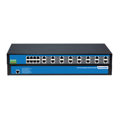
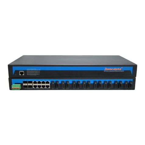
This product is a PTP layer 3 industrial Ethernet switch, and
its model is: ICS5400PTP-12GT12GS4XS (12 Gigabit
Ethernet ports + 12 Gigabit Ethernet SFP fiber ports + 4
10Gigabit Ethernet SFP+ fiber ports, 12~48VDC dual power
input).
【Panel Design】
Front panel
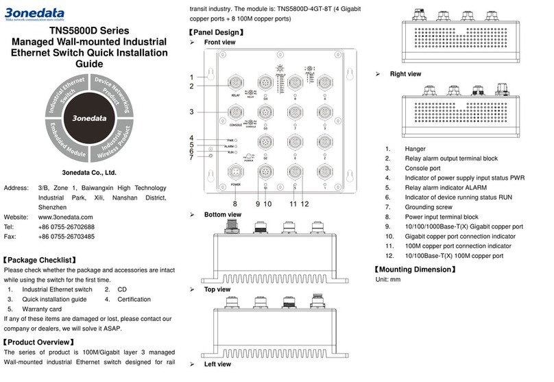
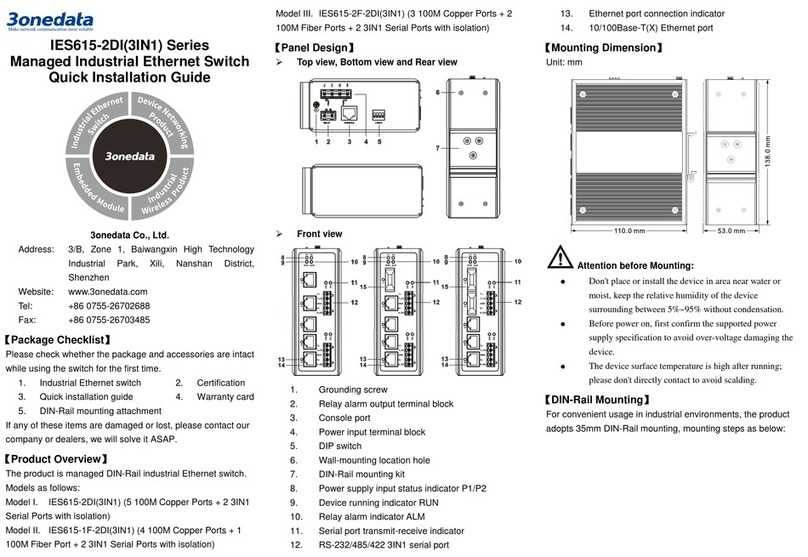
1. Grounding screw
2. Power indicator (P1/P2)
3. Lugs
4. Relay input terminal (RELAY, reserved)
5. Power supply input (P1/P2)
6. Console port
7. Device running state indicator (RUN)
8. Alarm indicator (ALM)
9. Gigabit Ethernet copper port (G1-G12)
10. Gigabit Ethernet copper port indicator (G1-G12)
11. Gigabit SFP interface (G13-G24)
12. Gigabit SFP interface indicator (G13-G24)
13. 10Gigabit SFP+ interface (X1-X4)
14. 10Gigabit SFP+ interface indicator (X1-X4)
15. PPS interface
【Mounting Dimension】
Unit: mm
Notice Before Mounting:
Don't place or install the device in area near water or
moist, keep the relative humidity of the device
surrounding between 5%~95% without condensation.
Before power on, first confirm the supported power
supply specification to avoid over-voltage damaging
the device.
The device surface temperature is high after running;
please don't directly contact to avoid scalding.
【Rack-mounted】
This product adopts rack-mounting, mounting steps as
below:
Step 1 Select the device mounting position and ensure
enough mounting size is reserved.
Step 2 Adopt 4 bolts to install the mounting lugs in the
device position as figure below.
Step 3 Place the device in the rack; adopt 4 bolts to fix
two sides mounting lugs in the rack.
Step 4 Check and confirm the product is mounted firmly
on the rack, mounting ends.
【Disassembling Device】
Step 1 Power off the device.
Step 2 Adopt screw driver to loosen the 4 bolts fixed on
the mounting lugs in the rack.
Step 3 Shift out the device from rack, disassembling
ends.
Notice before power on:
Power ON operation: First insert the power supply
terminal block into the device power supply interface,
then plug the power supply plug contact and power
on.
Power OFF operation: First, remove the power plug,
then remove the wiring section of terminal block.
Please pay attention to the above operation sequence.
Please be aware of the power input range supported
by the device before powering on. Use the
recommended voltage of the device to avoid device
damage.
【Power Supply Connection】
The device supports 2
12~48VDC power
inputs (compatible
with 90~264VAC), and adopts 7-pin 5.08mm pitch terminals,
and the power supply occupies the right 5 pins. This power
supply supports anti-reverse connection.
【Relay Connection】
The device supports 1
relay alarm
information output,
using 7-pin 5.08mm
pitch terminal blocks, and the relay occupies 2 bits on the
left. They are open circuit in normal non alarm state, closed
when any alarm information occurs. The relay can externally
connect to alarm lights or alarm buzzer or other switching
value collecting device in order to timely notify operators
when the alarm occurs.
Note:
Relay terminals are reserved and not open yet.
【Console Port Connection】
The device provides 1 program debugging port based on
RS-232 serial port which can conduct device CLI command
management after connecting to PC. The interface adopts
RJ45 port, the RJ45 pin definition is as follows:
Pin No.
2
3
5
Pin Definition
TXD
RXD
GND
【Checking LED Indicator】
The series product provides LED indicators to monitor the
device working status with a comprehensive simplified
troubleshooting; the function of each LED is described in the
table as below:
LED
Indicate
Description
P1
ON Power supply is connected
and running normally
OFF Power supply is disconnected
or running abnormally
P2
ON PWR is connected and
running normally
OFF Power supply is disconnected
or running abnormally
RUN
Blinking The system is running
normally
OFF The system is not running or
running abnormally
ON The system is running
abnormally
ALM
ON Power supply or port link has
alarm
OFF Power supply, port link without
alarm
Link
(G1-G24,
X1-X4)
ON Port has established valid
network connection
Blinking Port is in a network
communication status
LED
Indicate
Description
OFF Port hasn’t established valid
network connection.
【Logging in to WEB Interface】
This device supports WEB management and configuration.
Computer can access the device via Ethernet interface. The
way of logging in to device’s configuration interface via IE
browser is shown as below:
Step 1 Configure the IP addresses of computer and the
device to the same network segment, and the
network between them can be mutually
accessed.
Step 2 Enter device’s IP address in the address bar of
the computer browser.
Step 3 Enter device’s username and password in the
login window as shown below.
Step 4 Click “Login” button to login to the WEB interface
of the device.
Note:
The default IP address of the device is
“192.168.1.254”.
The default user name of the device is “admin”, no
password.
If the user name or password is lost, user can restore it
to factory settings via restoring factory setting button
or management software; all modified configurations
will be cleared after restoring to factory settings, so
please backup configuration file in advance.
Please refer to user manual for specific configuration
method of logging in to WEB interface and other
configurations about network management function.
【Specification】
Panel
Gigabit copper
port
10/100/1000Base-T(X) self-adapting
RJ45 port, half/full duplex
self-adaption or forced working mode,
support MDI/ MDI-X self-adaption
Gigabit SFP 100/1000Base-X self-adaptive SFP+
slot
10GbE interface
10GbE SFP+ port (10Gigabit /
Gigabit self-adaption)
Console port
CLI command management port
(RS-232), RJ45
Alarm interface
(reserved)
7-pin 5.08mm pitch terminal blocks,
relay occupies 2 pins on the left,
support 2 relay alarm output
PPS Support 1 PPS signal input, adopting
BNC interface to connect an external
time source
Indicator
Power indicator, system alarm
indicator, devic
e running status
indicator, interface
connection/running status indicator
Switch Property
Backplane
bandwidth
128G
Packet buffer
size
32Mbit
MAC Address
Table
32K
Power Supply
Input power
supply
12~48VDC (compatible with
90~264VAC), dual power supply
Access terminal
block
7-
pin 5.08mm pitch terminal blocks
(power supply occupies 5 pins on the
right)
Power Consumption
No-load Normal temperature: 28.2W@48VDC
High temperature: 34.0W@48VDC
Full-load Normal temperature: 33.1W@48VDC
High temperature: 38.5W@48VDC
Working Environment
Working
temperature
-40~60℃
Storage
temperature
-40~85℃
Working
humidity
5%~95% (no condensation)
Protection grade
IP40 (metal shell)

Other 3One data Switch manuals

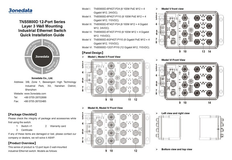
3One data TNS5800 Series User manual

3One data

3One data TNS5800 Series User manual

3One data ES1024 User manual

3One data

3One data ES1024 User manual

3One data TNS5500 Series User manual

3One data

3One data TNS5500 Series User manual

3One data IES6300-8GHP2GS2HS-2P48-360W User manual

3One data

3One data IES6300-8GHP2GS2HS-2P48-360W User manual

3One data PS5026G-2GS-24PoE User manual

3One data

3One data PS5026G-2GS-24PoE User manual

3One data PS1005G-1GT-4POE Operating and maintenance instructions

3One data

3One data PS1005G-1GT-4POE Operating and maintenance instructions

3One data IES5028 Series User manual

3One data

3One data IES5028 Series User manual

3One data IES215-1GX-4G User manual

3One data

3One data IES215-1GX-4G User manual

3One data IES6300PRO Series User manual

3One data

3One data IES6300PRO Series User manual

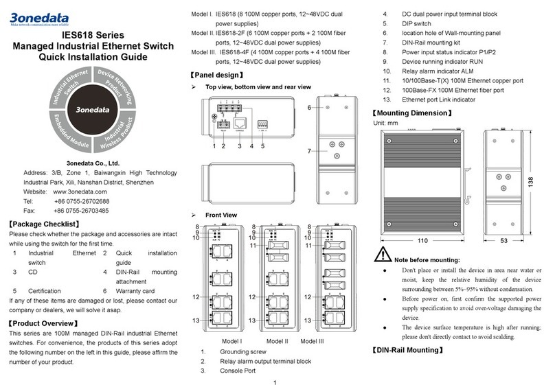
3One data IES618 Series User manual

3One data

3One data IES618 Series User manual
3One data IES2305 Series User manual

3One data

3One data IES2305 Series User manual

3One data IES6100 Series User manual

3One data

3One data IES6100 Series User manual

3One data IPS716-2GC-4POE User manual

3One data

3One data IPS716-2GC-4POE User manual

3One data IES2016-16T Series User manual

3One data

3One data IES2016-16T Series User manual

3One data IES6220 Series User manual

3One data

3One data IES6220 Series User manual

3One data IES2210 Series User manual

3One data

3One data IES2210 Series User manual

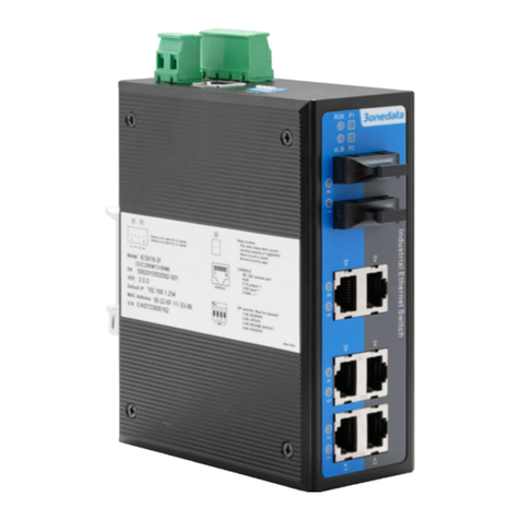
3One data IES618 Series User manual

3One data

3One data IES618 Series User manual

3One data ICS5530 Series User manual

3One data

3One data ICS5530 Series User manual

3One data IES5024-20F User manual

3One data

3One data IES5024-20F User manual

3One data ICS5530-16GS8GC6XS-2P220 User manual

3One data

3One data ICS5530-16GS8GC6XS-2P220 User manual

3One data ICS6400-12GT12GS4XS User manual
3One data

3One data ICS6400-12GT12GS4XS User manual

3One data IES7110 3GS Series User manual

3One data

3One data IES7110 3GS Series User manual

3One data IES3016 Series User manual

3One data

3One data IES3016 Series User manual

3One data IES205 Manual

3One data

3One data IES205 Manual

Popular Switch manuals by other brands

HP V1910 user guide

HP

HP V1910 user guide

EtherWAN OttoE TG103 Series installation guide

EtherWAN

EtherWAN OttoE TG103 Series installation guide

GE SecoGear Application guide

GE

GE SecoGear Application guide

EUCHNER CTP operating instructions

EUCHNER

EUCHNER CTP operating instructions

EtherWAN InfraGreEn IG5 installation guide

EtherWAN

EtherWAN InfraGreEn IG5 installation guide

SpectraLink TGA116 supplementary guide

SpectraLink

SpectraLink TGA116 supplementary guide

Belkin OmniView F1DP101Mea user manual

Belkin

Belkin OmniView F1DP101Mea user manual

SICK i110P operating instructions

SICK

SICK i110P operating instructions

H3C S3600V3 Series Compliance and Safety Manual

H3C

H3C S3600V3 Series Compliance and Safety Manual

TRENDnet TE100-S50g Quick installation guide

TRENDnet

TRENDnet TE100-S50g Quick installation guide

QNAP QSW-308 Quick installation guide

QNAP

QNAP QSW-308 Quick installation guide

Honeywell RXSM100A3 owner's manual

Honeywell

Honeywell RXSM100A3 owner's manual

cable matters 202010 user manual

cable matters

cable matters 202010 user manual

NETGEAR GS104 installation guide

NETGEAR

NETGEAR GS104 installation guide

ATEN CS1784 user manual

ATEN

ATEN CS1784 user manual

NETGEAR ProSafe FS726AT Brochure & specs

NETGEAR

NETGEAR ProSafe FS726AT Brochure & specs

SMC Networks ZSE20A Operation manual

SMC Networks

SMC Networks ZSE20A Operation manual

Chipset Communication USB-DS21 Quick installation guide

Chipset Communication

Chipset Communication USB-DS21 Quick installation guide

manuals.online logo
manuals.online logoBrands
  • About & Mission
  • Contact us
  • Privacy Policy
  • Terms and Conditions

Copyright 2025 Manuals.Online. All Rights Reserved.