manuals.online logo
Brands
  1. Home
  2. •
  3. Brands
  4. •
  5. 3One data
  6. •
  7. Switch
  8. •
  9. 3One data IES206 Series User manual

3One data IES206 Series User manual

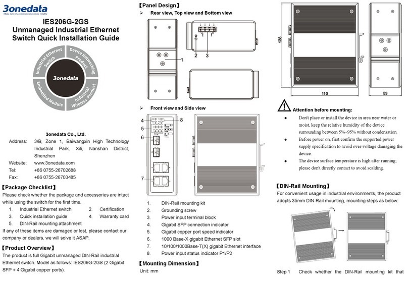
IES206 Series
Unmanaged Industrial Ethernet
Switch Quick Installation Guide
3onedata Co., Ltd.
Address:
3/B, Zone 1, Baiwangxin High Technology
Industrial Park, Xili, Nanshan District,
Shenzhen
Website:
www.3onedata.com
Tel:
+86 0755-26702688
Fax:
+86 0755-26703485
【Package Checklist】
Please check whether the package and accessories are intact
while using the switch for the first time.
1.
Industrial Ethernet switch
2.
Certification
3.
Quick installation guide
4.
Warranty card
5.
DIN-Rail mounting attachment
If any of these items are damaged or lost, please contact our
company or dealers, we will solve it ASAP.
【Product Overview】
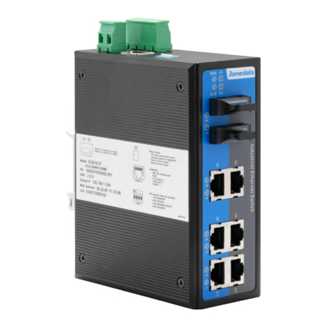
The series products are unmanaged industrial Ethernet switch.
Models as follows:
Model I. IES206-2GF-2P (12~48VDC) (2 Gigabit Fiber Ports
+ 4 100M Copper Ports, 12~48VDC Dual Power
Supply)
Model II.IES206-2GF-P (220VAC) (2 Gigabit Fiber Ports + 4
100M Copper Ports, 100~240VAC)
Model III. IES206-2GS (2 Gigabit SFP Slots + 4 100M
Copper ports, 12~48VDC Dual Power Supply)
【Panel Design】
Model l: Top view, Bottom view and Rear view
Model l: Front view and Side view
1. Grounding screw
2. DC power input terminal block
3. Location hole for wall mounting
4. DIN-Rail mounting kit
5. Device running indicator RUN
6. Ethernet port status indicator
7. 1000Base-FX Gigabit Ethernet fiber port
8. 10/100Base-T(X) 100M Ethernet copper port
Model II: Top view, Bottom view and Rear view
Model II: Front view and Side view
1. Grounding screw
2. AC power input terminal block
3. Location hole for wall mounting
4. DIN-Rail mounting kit
5. Device running indicator RUN
6. Ethernet port status indicator
7. 1000Base-FX Gigabit Ethernet fiber port
8. 10/100Base-T(X) 100M Ethernet copper port
Model lII: Top view, Bottom view and Rear view
Model III: Front view and Side view
1. Grounding screw
2. DC power input terminal block
3. Location hole for wall mounting
4. DIN-Rail mounting kit
5. Device power status indicator PWR
6. Gigabit Ethernet SFP port status indicator
7. 1000Base-SFP Gigabit Ethernet SFP slot
8. 10/100Base-T(X) 100M Ethernet copper port with
indicator
【Mounting Dimension】
Unit: mm
Model I and Model II
Model III
Attention before mounting:
Don't place or install the device in area near water or
moist, keep the relative humidity of the device
surrounding between 5%~95% without condensation.
Before power on, first confirm the supported power
supply specification to avoid over-voltage damaging the
device.
The device surface temperature is high after running;
please don't directly contact to avoid scalding.
【DIN-Rail Mounting】
For convenient usage in industrial environments, the product
adopts 35mm DIN-Rail mounting, mounting steps as below:
Check whether the DIN-Rail mounting kit thatStep 1 comes with the device is installed firmly.
Insert the bottom of DIN-Rail mounting kit (one sideStep 2 with spring support) into DIN-Rail, and then insert
the top into DIN-Rail.
Tips:
Insert a little to the bottom, lift upward and then insert
to the top.
Check and confirm the product is firmly installed onStep 3 DIN-Rail, and then mounting ends.
【Disassembling DIN-Rail】
Power off the device.Step 1 After lift the device upward slightly, first shift out theStep 2 top of DIN-Rail mounting kit, and then shift out the
bottom of DIN-Rail, disassembling ends.
Attention before powering on:
Power ON operation: first connect power line to the
connection terminal of device power supply, and then
power on.
Power OFF operation: first unpin the power plug, and
then remove the power line, please note the operation
order above.
【Power Supply Connection】
Model I: DC power supply
The Model I provides 4 pins power
supply input terminal blocks and two
independent DC power supply
systems of PWR1 and PWR2. The
power supply supports nonpolarity
and anti-reverse connection. It can normally operate after
reverse connection. Power supply range: 12~48VDC
Model Il: AC power supply
The Model II provides 4 pins power
supply input terminal blocks and 1
AC power supply system. Power
supply range: 100~240VAC
Model Ill: DC power supply
The Model III provides 4 pins power
supply input terminal blocks and two
independent DC power supply
systems of PWR1 and PWR2. The
power supply supports nonpolarity
and anti-reverse connection. It can
normally operate after reverse connection. Power supply
range: 12~48VDC
【Checking LED Indicator】
This device provides LED indicators to monitor device’s
operating states, which has simplified the process of
troubleshooting comprehensively. The detailed status of each
LED is described in the table as below:
Model I and Model II
LED
Status
Description
RUN
ON The device is powered on or
in abnormal condition
OFF The device is not powered on
or in abnormal condition
Blinking
Blink once per second, the
device is running normally
Link/Act
(1-4/G1-G2)
ON The Ethernet
port has
established valid network
connection
Blinking The Ethernet port is in an
active network status
OFF The Ethernet
port has not
established
valid network
connection
Model III
LED
Status
Description
PWR ON PWR is connected and
running normally
OFF PWR is disconnected and
running abnormally.
5-6
ON The Port 5-6 has
established valid network
connection
Blinking The Port 5-6 is in an active
network status
OFF The Port 5-6
has not
established valid network
connection
RJ45
LED
(1-4)
10/100M ON The Port 1-4 is in 100M
operating mode
OFF The Port 1-4
is in 10M
operating mode
Link/
ACT
ON The Port 1-4 has
established valid network
connection
Blinking The Port 1-4 is in an active
network status
OFF The Port 1-4
has not
established valid network
connection
【Specification】
Panel
Gigabit fiber port 1000Base-FX, optional
SC/ST/FC
Gigabit SFP
1000Base-SFP, SFP slot
100M copper port 10/100Base-T(X), self-adaptive
RJ45 port, self-adaptive full/half
duplex, support MDI/MDI-X
self-adaption
Indicator
Power indicator, running
indicator, interface indicator
Switch property
Backplane bandwidth
7.6G
Packet buffer size
1Mbit
MAC address table
8K
Power supply
Input power supply
DC dual power supply
device
Power supply range: 12~48VDC
Power protection: dual power
redundancy backup,
anti-reverse connection
AC single power supply
device
Power supply range:
100~240VAC
Access terminal 4-core 7.62mm
pitch terminal
block
Consumption
Model I No-load: 3.8W@24VDC
Full-load: 5.5W@24VDC
Model II No-load: 4.4W@220VAC
Full-load: 5.6W@220VAC
Model III No-load: 5.9W@24VDC
Full-load: 7.3W@24VDC
Environmental Limits
Working temperature
-40
~
75
℃
Storage temperature
-40
~
85
℃
Working humidity
5%
~
95% (no condensation)
Protection grade
IP40 (metal shell)

This manual suits for next models

3

Other 3One data Switch manuals

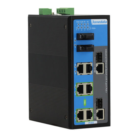
3One data IPS7110-2GC-8POE User manual

3One data

3One data IPS7110-2GC-8POE User manual

3One data IES6100PN-8T-2LV User manual

3One data

3One data IES6100PN-8T-2LV User manual

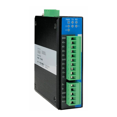
3One data TNS5800D Series User manual

3One data

3One data TNS5800D Series User manual

3One data IES6306 Series User manual

3One data

3One data IES6306 Series User manual

3One data ES1026-2F User manual

3One data

3One data ES1026-2F User manual

3One data IES6220 Series User manual

3One data

3One data IES6220 Series User manual

3One data IES5028-4GS-2F User manual

3One data

3One data IES5028-4GS-2F User manual

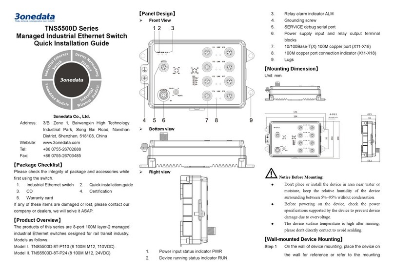
3One data TNS5500D Series User manual

3One data

3One data TNS5500D Series User manual

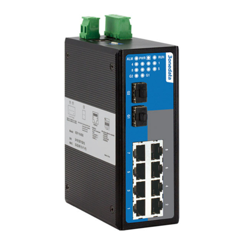
3One data IPS7110-2GC-4POE Series User manual
3One data

3One data IPS7110-2GC-4POE Series User manual

3One data TNS5800 Series User manual

3One data

3One data TNS5800 Series User manual

3One data IES7116G-8GS Series User manual

3One data

3One data IES7116G-8GS Series User manual

3One data TNS5800 Series User manual

3One data

3One data TNS5800 Series User manual

3One data IPS716-2GC-4POE User manual

3One data

3One data IPS716-2GC-4POE User manual

3One data ES5018 User manual

3One data

3One data ES5018 User manual

3One data IPS7112G-4GS-8GPOE User manual

3One data

3One data IPS7112G-4GS-8GPOE User manual

3One data IES7120G Series User manual

3One data

3One data IES7120G Series User manual

3One data ICS5400TSN-24GT16GS4XS-LN Series User manual

3One data

3One data ICS5400TSN-24GT16GS4XS-LN Series User manual

3One data IES7120-4GS Series User manual

3One data

3One data IES7120-4GS Series User manual

3One data SW4485I User manual

3One data

3One data SW4485I User manual

3One data IES5028G-4GS-8GC User manual
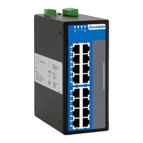
3One data

3One data IES5028G-4GS-8GC User manual

3One data ES5026 User manual

3One data

3One data ES5026 User manual

3One data IES6320 Series User manual

3One data

3One data IES6320 Series User manual

3One data IPS215-4POE User manual

3One data

3One data IPS215-4POE User manual

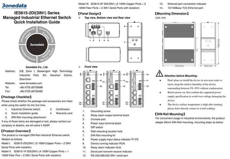
3One data IES2016-16T Series User manual

3One data

3One data IES2016-16T Series User manual

Popular Switch manuals by other brands

Cisco Nexus 5596 Hardware installation guide

Cisco

Cisco Nexus 5596 Hardware installation guide

Intelix AS-2H-WP Installation and operation guide

Intelix

Intelix AS-2H-WP Installation and operation guide

Kramer VS-211H user manual

Kramer

Kramer VS-211H user manual

Extron electronics ISS 608 Setup guide

Extron electronics

Extron electronics ISS 608 Setup guide

SMC Networks EZ Switch SMC8506T installation guide

SMC Networks

SMC Networks EZ Switch SMC8506T installation guide

Cisco Nexus 7000 Series Configuration guide

Cisco

Cisco Nexus 7000 Series Configuration guide

ATEN CubiQ CM0264 user manual

ATEN

ATEN CubiQ CM0264 user manual

Aukey CB-H18 user manual

Aukey

Aukey CB-H18 user manual

D-Link DGS-1210-52MP Quick installation guide

D-Link

D-Link DGS-1210-52MP Quick installation guide

Eneo IAM-5SE1004MUC user manual

Eneo

Eneo IAM-5SE1004MUC user manual

ZyXEL Communications GS2200-24 Series Specifications

ZyXEL Communications

ZyXEL Communications GS2200-24 Series Specifications

ZyXEL Communications ZyXEL PLA-470 Specifications

ZyXEL Communications

ZyXEL Communications ZyXEL PLA-470 Specifications

Valcom V-2970 brochure

Valcom

Valcom V-2970 brochure

Selve i-Switch operating instructions

Selve

Selve i-Switch operating instructions

Cisco Catalyst 2955 Series Installation notes

Cisco

Cisco Catalyst 2955 Series Installation notes

Digitus DN-95341 user manual

Digitus

Digitus DN-95341 user manual

Assa Abloy Aperio AH30 installation instructions

Assa Abloy

Assa Abloy Aperio AH30 installation instructions

StarTech.com ST4205READ user guide

StarTech.com

StarTech.com ST4205READ user guide

manuals.online logo
manuals.online logoBrands
  • About & Mission
  • Contact us
  • Privacy Policy
  • Terms and Conditions

Copyright 2025 Manuals.Online. All Rights Reserved.