manuals.online logo
Brands
  1. Home
  2. •
  3. Brands
  4. •
  5. 3One data
  6. •
  7. Switch
  8. •
  9. 3One data SW4485I User manual

3One data SW4485I User manual

SW4485I HUB
Quick Installation Guide
3onedata Co., Ltd.
Address: 3/B, Zone 1, Baiwangxin High Technology
Industrial Park, Song Bai Road, Nanshan
District, Shenzhen, 518108, China
Website: www.3onedata.com
Tel: +86 0755-26702688
Fax: +86 0755-26703485
【Package Checklist】
Please check the integrity of package and accessories while
first using the product.
1. Hub x1 (with terminal block)
2. Quick installation guide
3. DIN-Rail mounting attachment
4. Warranty card
5. Certification
If any of these items are damaged or lost, please contact our
company or dealers, we will solve it ASAP.
【Product Overview】
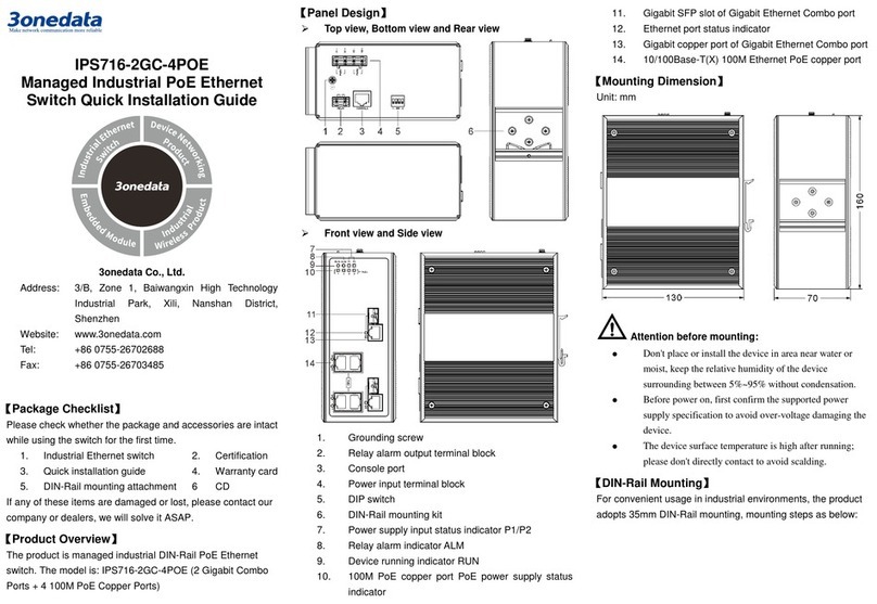
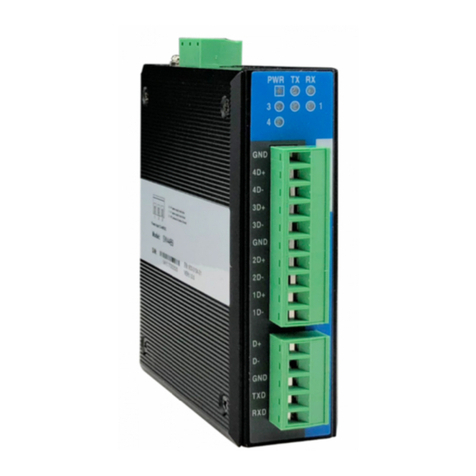
This product is a hub. The model is: SW4485I (1
RS-232/485 + 4 RS-485).
【Panel Design】
Rear view, Bottom view and Top view
Front View
1. DIN-Rail mounting kit
2. Terminal block for power input
3. Grounding screw
4. Data sending status indicator of upper device (TX)
5. Power indicator
6. Data receiving status indicator of upper device (RX)
7. RS-485 interface status indicator light of the lower
device (1-4)
8. RS-485 interface of the lower device
9. RS-232/485 interface of the upper device
【Mounting Dimension】
Unit: mm
Notice before mounting:

Don't place or install the device in area near water or
moist, keep the relative humidity of the device
surrounding between 5%~95% without condensation.

Before power on, first confirm the supported power
supply specification to avoid over-voltage damaging the
device.

The device surface temperature is high after running;
please don't directly contact to avoid scalding.
【DIN-Rail Mounting】
The product adopts 35mm standard DIN-Rail mounting which
is suitable for most industrial scenes, mounting steps as
follows:
Check if the DIN-Rail mounting kit is installed firmly.
Step 1
Insert the bottom of DIN-Rail mounting kit (one side
Step 2
with spring support) into DIN-Rail, and then insert
the top into DIN-Rail.
Tips:
Insert a little to the bottom, lift upward and then insert
to the top.
Check and confirm the product is firmly installed on
Step 3
DIN-Rail, then mounting ends.
【Disassembling DIN-Rail】
Device power off.
Step 1
After lift the device upward slightly, first shift out the
Step 2
top of DIN-Rail mounting kit, and then shift out the
bottom of DIN-Rail, disassembling ends.
Notice before power on:

Power ON operation: First insert the power supply
terminal block into the device power supply interface,
and then plug the power supply plug contact and power
on.

Power OFF operation: First, remove the power plug,
and then remove the wiring section of terminal block.
Please pay attention to the above operation sequence.
【Power Supply Connection】
The product provides 3-pin 7.62mm pitch
terminal blocks, in which 1 and 3 are power
input and 2 is grounding. The power supply has the function of
non-polarity and anti-reverse connection, and the device can
still work normally after the reverse connection.
Voltage range: 12VDC~48VDC.
【Serial Port Connection】
Lower device RS-485
The device provides 4 RS-485
lower device interfaces, the
interface type is 10-pin
5.08mm pitch terminal block, support 15kV electrostatic
protection, 2kVAC isolation protection. The pin definitions as
shown in the follow table:
PIN Definition Note
1. GND Signal ground
2. 4D+ RS-485 positive signal input
(out) terminal
3. 4D- RS-485 negative signal input
(out) terminal
4. 3D+ RS-485 positive signal input
(out) terminal
5. 3D- RS-485 negative signal input
(out) terminal
6. GND Signal ground
7. 2D+ RS-485 positive signal input
(out) terminal
8. 2D- RS-485 negative signal input
(out) terminal
9. 1D+ RS-485 positive signal input
(out) terminal
10. 1D- RS-485 negative signal input
(out) terminal
RS-232/485 serial port of the upper device
The device provides 1 RS-232/485 upper
device port, the interface form is 5-pin
5.08mm pitch terminal block, supports 15kV electrostatic
protection, 2kVAC isolation protection. The pin definitions as
shown in the follow table:
PIN Definition Note
1. D+ RS-485 positive signal input (out)
2. D- RS-485 negative signal input
3. GND RS-232 signal ground wire
4. TxD RS-232 data sending terminal
5. RxD RS-232 data receiving terminal
【Checking LED Indicator】
The device provides LED indicators to monitor the device
working status with a comprehensive simplified
troubleshooting; the function of each LED is described in the
table as below:
LED Indicate Description
PWR
ON PWR is connected and running
normally
OFF PWR is disconnected and running
abnormally
1-4
ON
The device is normally powered on,
and the corresponding interface
from D1 ~ D4 is in the state of
receiving/sending data
Blinking D1~D4 corresponding interfaces
are sending/receiving data
OFF
Fault warning: the device is not
powered on or the device is
normally powered on, D1~D4
corresponding interface signal line
is inversely connected
TX
Blinking transmitting data
OFF No data transmission
RX
Blinking receiving data
OFF No data receiving
【Specification】
Panel
RS-232/485 1 RS-232/485 serial port,
upper device interface, adopts
5-pin 5.08mm pitch terminal
blocks
RS-485 4 RS-485 serial port, lower
device interface, adopts
10-pin 5.08mm pitch terminal
blocks
Indicator Power indicator, serial port
data transmitting/receiving
indicator, lower device serial
port indicator
Power Supply
Input power supply Power input voltage:
12~48VDC
Support nonpolarity
Access terminal block 3-pin 7.62mm pitch terminal
blocks
Power Consumption
No-load 0.696W@24VDC
Full-load 0.696W@24VDC
Working Environment
Working temperature -40~75℃
Storage temperature -40~85℃
Working humidity 5%~95% (no condensation)

Protection grade IP40(metal shell)

Other 3One data Switch manuals

3One data IES5328 Series User manual

3One data

3One data IES5328 Series User manual

3One data IES618 Series User manual

3One data

3One data IES618 Series User manual

3One data IPS3110 Series User manual

3One data

3One data IPS3110 Series User manual

3One data IPS7110 Series User manual

3One data

3One data IPS7110 Series User manual

3One data IES6300PRO Series User manual

3One data

3One data IES6300PRO Series User manual

3One data IES7120-4GS Series User manual

3One data

3One data IES7120-4GS Series User manual

3One data IES206G-2GS User manual

3One data

3One data IES206G-2GS User manual

3One data TNS5800D Series User manual

3One data

3One data TNS5800D Series User manual

3One data IPS716-2GC-4POE User manual

3One data

3One data IPS716-2GC-4POE User manual

3One data ES1016 User manual

3One data

3One data ES1016 User manual

3One data IES5028G-4GS-8GC User manual

3One data

3One data IES5028G-4GS-8GC User manual

3One data IES2010 Series User manual

3One data

3One data IES2010 Series User manual

3One data IES6306 Series User manual

3One data

3One data IES6306 Series User manual

3One data IES2008-8T-P48 User manual

3One data

3One data IES2008-8T-P48 User manual

3One data IES318 Series User manual

3One data

3One data IES318 Series User manual

3One data IES206 Series User manual

3One data

3One data IES206 Series User manual

3One data IES618-4D Series User manual

3One data

3One data IES618-4D Series User manual

3One data IES6300 Series User manual

3One data

3One data IES6300 Series User manual

3One data TNS5500 Series User manual

3One data

3One data TNS5500 Series User manual

3One data PS5026G-2GS-24PoE Operating and maintenance instructions

3One data

3One data PS5026G-2GS-24PoE Operating and maintenance instructions

3One data IES6300 Series User manual

3One data

3One data IES6300 Series User manual

3One data IES6210 Series User manual

3One data

3One data IES6210 Series User manual

3One data IES6100PN-8T-2LV User manual

3One data

3One data IES6100PN-8T-2LV User manual

3One data ICS5000-E24GP4GS User manual

3One data

3One data ICS5000-E24GP4GS User manual

Popular Switch manuals by other brands

Zte ZXR10 5900 Series Product description

Zte

Zte ZXR10 5900 Series Product description

Hawking CS164 user manual

Hawking

Hawking CS164 user manual

Escient ZONE LS102 installation guide

Escient

Escient ZONE LS102 installation guide

Moxa Technologies EDS-408A user manual

Moxa Technologies

Moxa Technologies EDS-408A user manual

TP-Link JetStream T1500-28PCT user guide

TP-Link

TP-Link JetStream T1500-28PCT user guide

Renesas Emulation Pod for M30240 Group MCUs... user manual

Renesas

Renesas Emulation Pod for M30240 Group MCUs... user manual

ADTRAN NetVanta 1638 Hardware installation guide

ADTRAN

ADTRAN NetVanta 1638 Hardware installation guide

Alloy POEFE8TV2 user manual

Alloy

Alloy POEFE8TV2 user manual

3Com Baseline 2226-PWR Plus user guide

3Com

3Com Baseline 2226-PWR Plus user guide

Extreme Networks 200 Series Installation and user guide

Extreme Networks

Extreme Networks 200 Series Installation and user guide

Leviton Decora L5614 Installation

Leviton

Leviton Decora L5614 Installation

HP V1810-48G Quick setup guide

HP

HP V1810-48G Quick setup guide

Longshine LCS-883R-SW2402 user manual

Longshine

Longshine LCS-883R-SW2402 user manual

Cisco 6500 - Catalyst Series 10 Gigabit EN Interface Module... Installation note

Cisco

Cisco 6500 - Catalyst Series 10 Gigabit EN Interface Module... Installation note

Wulian WL-SFB-S Series user manual

Wulian

Wulian WL-SFB-S Series user manual

Emulex Model 375 Quick install card

Emulex

Emulex Model 375 Quick install card

EUCHNER TQ2-1211SG024-5000 operating instructions

EUCHNER

EUCHNER TQ2-1211SG024-5000 operating instructions

TRENDnet TEG-S240TX - DATA SHEETS Specifications

TRENDnet

TRENDnet TEG-S240TX - DATA SHEETS Specifications

manuals.online logo
manuals.online logoBrands
  • About & Mission
  • Contact us
  • Privacy Policy
  • Terms and Conditions

Copyright 2025 Manuals.Online. All Rights Reserved.