manuals.online logo
Brands
  1. Home
  2. •
  3. Brands
  4. •
  5. 3One data
  6. •
  7. Switch
  8. •
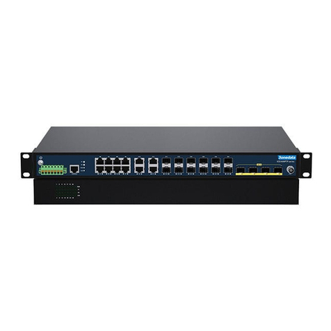
  9. 3One data IES5028G-4GS-8GC User manual

3One data IES5028G-4GS-8GC User manual

- 1 -
IES5028G-4GS-8GC
Industrial Layer 2 Ethernet Switch
Quick Installation Guide
3onedata Co., Ltd.
Address:
3/B, Zone 1, Baiwangxin High Technology
Industrial Park, Song Bai Road, Nanshan
District, Shenzhen, 518108, China
Website:
www.3onedata.com
Tel:
+86 0755-26702688
Fax:
+86 0755-26703485
【Package Checklist】
Please check the integrity of package and accessories while
first using the switch.
1.
Industrial Ethernet switch
2.
Power line x2(AC
device only)
3.
Quick installation guide
4.
Serial port line
5.
Rack-mounting lug x2
6.
Foot pad x4
7.
Software installation CD
8.
Warranty card
9.
Certification
If any of these items are damaged or lost, please contact our
company or dealers, we will solve it ASAP.
【Product Overview】
The product is managed industrial Ethernet switch. The
model is IES5028G-4GS-8GC (4 Gigabit SFP + 8 Gigabit
combo ports + 16 Gigabit copper ports).
【AC Panel Design】
Front panel
Rear panel
1. Ethernet port indicator
2. Gigabit Combo port
3. Gigabit Ethernet copper port
4. Gigabit SFP port
5. Console port
6. Device running status indicator
7. Restoring factory setting button
8. Alarm indicator
9. Power indicator (P1/P2)
10. Rack-mounting lug
11. Relay output terminal blocks
12. AC power input
13. Grounding screw
【DC Panel Design】
Front panel
Rear panel
1. Ethernet port indicator
2. Gigabit Combo port
3. Gigabit Ethernet copper port
4. Gigabit SFP port
5. Console port
6. Device running status indicator
7. Restoring factory setting button
8. Alarm indicator
9. Power indicator (P1/P2)
10. Rack-mounting lug
11. DC power input
12. Relay output terminal blocks
13. Grounding screw
【Mounting Dimension】
Unit: mm
Note:
Don't place or install the device in area near water or moist,
keep the relative humidity of the device surrounding between
5%~95% without condensation.
Before power on, first confirm the supported power supply
specification to avoid over-voltage damaging the device.
The device surface temperature is high after running; please
don't directly contact to avoid scalding.
【Rack-mounting】
This product adopts rack-mounting, mounting steps as
- 2 -
below:
Step 1 Select the device mounting position and ensure
enough mounting size is reserved.
Step 2 Adopt 4 bolts to install the mounting lugs in the
device position as figure below.
Step 3 Place the device in the rack; adopt 4 bolts to fix two
sides mounting lugs in the rack.
Step 4 Check and confirm the product is firmly installed on
the rack, then mounting ends.
【Disassembling Device】
Step 1 Power off device.
Step 2 Adopt screw driver to loosen the 4 bolts fixed on
the mounting lugs in the rack.
Step 3 Remove the device away from the rack,
disassembling ends.
Note before powering on:
Power ON operation: First insert the power supply terminal
block into the device power supply interface, and then plug
the power supply socket and power on.
Power switch “—” means power ON, “O” means power OFF.
Power OFF operation: First, put the powers switch to the "O"
side and then disconnect the power supply. Finally disconnect
the connector between the device and the power cord. Please
notice the operation order above.
【Power Supply Connection】
AC power supply
This device provides 2 AC power supply
access interfaces which come with a switch.
The power supply input range is
100~240VAC/DC.
DC power supply
This device provides 2 DC power
supplies which are 5-pin 5.08mm pitch
terminal blocks.The power supply
occupies 3 pins and supports anti-reverse connection.
Power supply range: 36~72VDC
【Restoring Default Settings】
RESET is restoring default settings button. Restoring default
settings steps as follows: Press and hold the RESET button,
disconnect the power supply and then power on the device,
wait for about 3~4 seconds to restore the factory settings.
【Relay Connection】
R+ and R- are the relay alarm output
section. They are open circuit in normal
non alarm state, closed when any
alarm information occurs. The product
supports 2-way relay alarm output, externally connected to
alarm lights or alarm buzzer or other switching value
collecting device in order to timely notify operators when the
alarm occurs.
【Console Port Connection】
The series products provide 1 program debugging port
based on RS-232 serial port which can conduct device CLI
command management after connecting to PC. It adopts
RJ45 interface, its pin definition is showed as follows:
Pin No.
2
3
5
Definition
TXD
RXD
GND
【Checking LED Indicator】
The series products provide LED indicators to monitor the
device working status with a comprehensive simplified
troubleshooting; the function of each LED is described in the
table as below:
LED
State
Description
P1
ON
Power supply is connected or
running normally
OFF
Power supply is disconnected or
running abnormally
P2
ON
Power supply is connected or
running normally
OFF
Power supply is disconnected or
running abnormally
RUN
Blinking
System is running normally
OFF
System is not running or running
abnormally
ON
System is running abnormally
ALM
ON
Power supply or the port’s link is
alarming.
OFF
Power and the port’s link exist no
alarm
Link
(G1-G28)
ON
Port connection is active
Blinking
Data transmitted
OFF
Port connection is not active
【Logging in to WEB Interface】
This device supports WEB management and configuration.
Computer can access the device via Ethernet interface. The
way of logging in to device’s configuration interface via IE
browser is shown as below:
Step 1 Configure the IP addresses of computer and the
device to the same network segment, and the
network between them can be mutually
accessed.
Step 2 Enter device’s IP address in the address bar of
- 3 -
the computer browser.
Step 3 Enter device’s username and password in the
login window as shown below.
Step 4 Click “OK” button to login to the WEB interface of
the device.
Note:
The default IP address of the device is
“192.168.1.254”.
The default username and password of the device is
“admin”.
If the username or password is lost, user can restore it
to factory settings via device DIP switch or
management software; all modified configurations
will be cleared after restoring to factory settings, so
please backup configuration file in advance.
Please refer to user manual for specific configuration
method of logging in to WEB interface and other
configurations about network management function.
【Specification】
Panel
Gigabit SFP interface
1000Base-SFP
1000M Combo port
10/100/1000Base-T(X) RJ45
or 1000 Base-SFP interface
optional
1000 Base-T(X)
10/100/1000 Base-T(X)
self-adapting RJ45 port,
half/full duplex self-adapting or
compulsive working mode,
support MDI/MDI-X
self-adapting
Console port
CLI command line
management port (RS-232),
RJ45
Alarm interface
5-pin 5.08mm pitch terminal
block (R+/R-), support 2 relay
alarm output
Indicator
Power indicator, system alarm
indicator, device running
status indicator, interface
connection/running status
indicator
Switch property
Backplane bandwidth
56G
Packet buffer size
12Mbit
MAC table size
16K
Power supply
Input power supply
100~240VAC/DC or
36~72VDC
Access terminal
Supports single-phase socket
with rocker switch
or 5-pin 5.08mm pitch terminal
blocks
Power consumption
No-load consumption
10.5W@220VAC
Full-load consumption
25.3W@220VAC
Working environment
Working temperature
-40~75℃
Storage temperature
-40~85℃
Working humidity
5%~95% (no condensation)
Protection grade
IP30 (aluminum shell)

Other 3One data Switch manuals

3One data ICS5400PTP-12GT12GS4XS User manual

3One data

3One data ICS5400PTP-12GT12GS4XS User manual

3One data ICS5400 Series User manual

3One data

3One data ICS5400 Series User manual
3One data TNS5800 Series User manual

3One data

3One data TNS5800 Series User manual
3One data ES209G-1GF User manual

3One data

3One data ES209G-1GF User manual

3One data IES5024 Series User manual

3One data

3One data IES5024 Series User manual
3One data ICS5428 Series User manual

3One data

3One data ICS5428 Series User manual
3One data IES6306 Series User manual

3One data

3One data IES6306 Series User manual
3One data IES7110-2GS Series User manual
3One data

3One data IES7110-2GS Series User manual

3One data IES618 Series User manual

3One data

3One data IES618 Series User manual

3One data IES2220 Series User manual

3One data

3One data IES2220 Series User manual

3One data IES318 Series User manual

3One data

3One data IES318 Series User manual
3One data IES2005 User manual

3One data

3One data IES2005 User manual
3One data IPS215 Series User manual

3One data

3One data IPS215 Series User manual

3One data MES600 Series User manual

3One data

3One data MES600 Series User manual
3One data IES7110 3GS Series User manual
3One data

3One data IES7110 3GS Series User manual

3One data IES206 Series User manual

3One data

3One data IES206 Series User manual
3One data IES6210 Series User manual

3One data

3One data IES6210 Series User manual
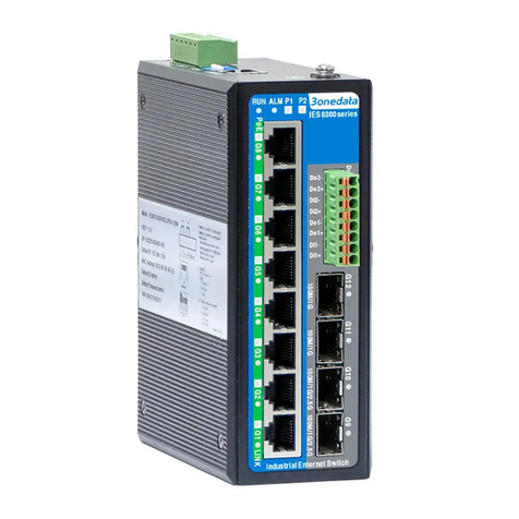
3One data IES6300 Series User manual

3One data

3One data IES6300 Series User manual
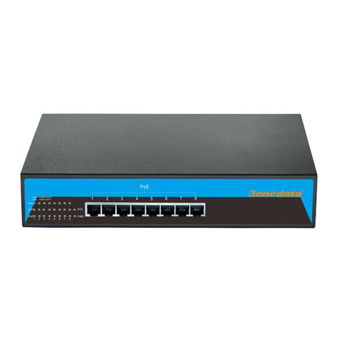
3One data ES1008G-8POE-150W-P User manual
3One data

3One data ES1008G-8POE-150W-P User manual

3One data ES5026 User manual

3One data

3One data ES5026 User manual

3One data IES2100SL Series User manual

3One data

3One data IES2100SL Series User manual

3One data ICS5530 Series User manual

3One data

3One data ICS5530 Series User manual

3One data IES205 Manual

3One data

3One data IES205 Manual

3One data SW4485I User manual

3One data

3One data SW4485I User manual

Popular Switch manuals by other brands
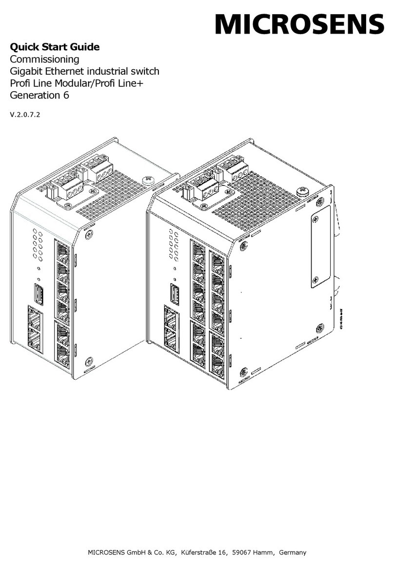
Microsens Profi Line Modular SERIES quick start guide
Microsens

Microsens Profi Line Modular SERIES quick start guide

PCB Piezotronics IMI SENSORS 685B1001A21 Installation and operating manual
PCB Piezotronics

PCB Piezotronics IMI SENSORS 685B1001A21 Installation and operating manual

esera automation 11220 V2 user guide

esera automation

esera automation 11220 V2 user guide
Panasonic PN28080K-TH installation guide
Panasonic

Panasonic PN28080K-TH installation guide

D-Link DGS-1016D - Switch Quick installation guide
D-Link

D-Link DGS-1016D - Switch Quick installation guide

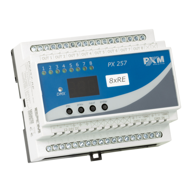
PXM PX257-OC user manual

PXM

PXM PX257-OC user manual

Huawei S5720I-6X-PWH-SI-AC quick start guide

Huawei

Huawei S5720I-6X-PWH-SI-AC quick start guide

Dell PowerConnect 3248 manual

Dell

Dell PowerConnect 3248 manual

Lantech IPES-5408T user manual

Lantech

Lantech IPES-5408T user manual

Omron A datasheet

Omron

Omron A datasheet

Compex SXP1224B datasheet

Compex

Compex SXP1224B datasheet

TRENDnet TEG-S4000 user guide

TRENDnet

TRENDnet TEG-S4000 user guide

Milnor KURSPK0025 Instruction

Milnor

Milnor KURSPK0025 Instruction

Fort ECSPHB quick start guide

Fort

Fort ECSPHB quick start guide

GoMax Electronics PS-5004V user manual
GoMax Electronics

GoMax Electronics PS-5004V user manual

D-Link DCH-G020 How-to

D-Link

D-Link DCH-G020 How-to

Brocade Communications Systems A7533A - Brocade 4Gb SAN Switch Base Command reference

Brocade Communications Systems

Brocade Communications Systems A7533A - Brocade 4Gb SAN Switch Base Command reference
Lantech mini Switch 800 user guide

Lantech

Lantech mini Switch 800 user guide

manuals.online logo
manuals.online logoBrands
  • About & Mission
  • Contact us
  • Privacy Policy
  • Terms and Conditions

Copyright 2025 Manuals.Online. All Rights Reserved.