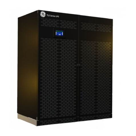
TLE Scalable Series 40 to 150 UL S1 UPS Installation Guide / REV-B
Table of content Page
1Safety rules..................................................................................................................................................................6
1.1 Safety symbols and warnings ......................................................................................................................................8
1.2 Cyber security ..................................................................................................................................................................8
2Layout ..........................................................................................................................................................................9
2.1 Layout TLE Scalable Series 40 to 150 .........................................................................................................................9
3Environment .............................................................................................................................................................. 11
3.1 Recycling instructions.................................................................................................................................................. 11
4Installation................................................................................................................................................................. 12
4.1 Transport ........................................................................................................................................................................ 12
4.1.1 Dimensions and weights TLE Scalable Series 40 to 150 .......................................................................... 13
4.2 Delivery ............................................................................................................................................................................15
4.3 Storage ............................................................................................................................................................................ 15
4.3.1 Storage of the UPS............................................................................................................................................15
4.3.2 Storage of Battery.............................................................................................................................................15
4.4 Place of installation ......................................................................................................................................................16
4.4.1 UPS location........................................................................................................................................................16
4.4.2 Battery location..................................................................................................................................................18
4.5 Ventilation and cooling................................................................................................................................................19
4.6 Unpacking ...................................................................................................................................................................... 20
4.7 Electrical wiring .............................................................................................................................................................22
4.7.1 Utility input connection ...................................................................................................................................22
4.7.2 Input/output over current protection and wire sizing.............................................................................23
4.7.3 Data for Input/output and Battery over current protection and wire sizing..................................... 24
4.7.4 Installation requirements ................................................................................................................................27
4.8 Wiring connection ........................................................................................................................................................ 30
4.8.1 TLE Scalable Series 40 to 150 - Power connection with Common Input Utility ..................................31
4.8.2 TLE Scalable Series 40 to 150 - Power connection with Dual Input Utility...........................................33
4.8.3 Battery cabinet connection to TLE Scalable Series 40 to 150.................................................................35
4.8.4 Use of TLE Scalable Series 40 to 150 in SEM Operation Mode (Super Eco Mode) .............................37
4.8.5 Use of TLE Scalable Series 40 to 150 as Frequency Converter .............................................................. 38
4.9 RPA Parallel System connection................................................................................................................................ 39
4.9.1 Power wiring of Parallel Units........................................................................................................................ 39
4.9.2 Parallel Control Bus connection .................................................................................................................... 40
4.9.3 Control bus cable location.............................................................................................................................. 42
4.10 “EPO - Emergency Power OFF” command connection........................................................................................ 44
5Connectivity interface..............................................................................................................................................45
5.1 Serial port J35µP - RS232 (Sub D, Female 9 pin).................................................................................................... 46
5.2 Customer interface board.......................................................................................................................................... 47
5.2.1 X1 terminal block - Output signals on voltage-free contacts................................................................. 48
5.2.2 X1 terminal block - Programmable input free contacts........................................................................... 48
5.2.3 X1 terminal block - Gen Set Signaling (GEN ON)........................................................................................ 49
5.2.4 X1 terminal block - AUX External Maintenance Bypass............................................................................ 49
5.2.5 X1 terminal block - SEM/IEMi control signal .............................................................................................. 49
5.3 “3-ph SNMP/WEB plug-in adapter” board.............................................................................................................. 50
5.4 “IM0305 - UVR control” board for CB3 Battery Breaker Box............................................................................... 50
6Options ...................................................................................................................................................................... 51
6.1 Top Cable Entry/Exit Sidecar (TCE) and Top Hat Fascia (THF)..........................................................................51
7Notes ..........................................................................................................................................................................53
7.1 Notes form......................................................................................................................................................................53
