11B
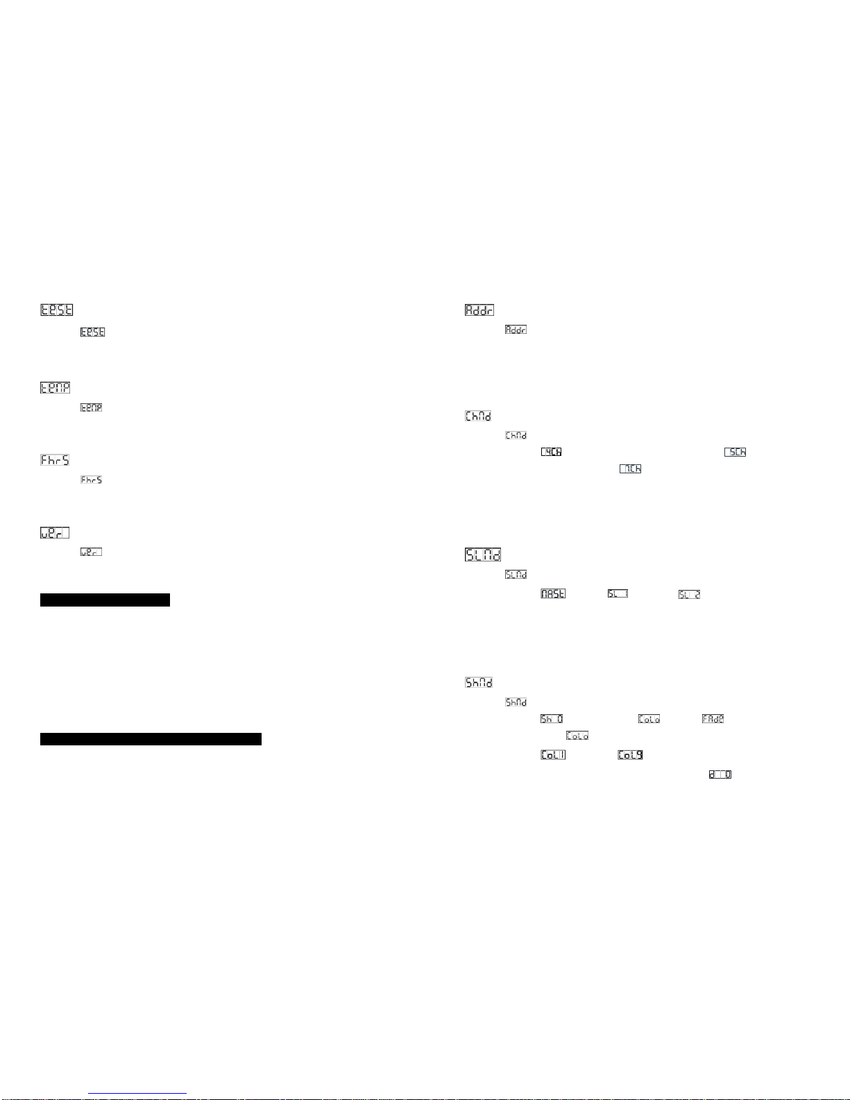
Auto Test
Select the , press the ENTER button and the unit will run the built-in programmer for
self-test. To go back to the functions press the MENU button.
Fixture Temperature
Select the , press the ENTER button and the display will show the temperature of the
unit. To go back to the functions press the MENU button again.
Fixture use time
Select the , press the ENTER button and the display will show the number of working
hours of the unit. To go back to the functions press the MENU button.
Software version
Select the , press the ENTER button and the display will show the version of software of
the unit. To go back to the functions press the MENU button again.
4. How to Control the Unit
You can operate the unit in three ways:
1. By master/slave built-in preprogram function
2. By easy controller
3. By DMX controller
No need to turn the unit off when you change the DMX address, as new DMX address setting
will be affected at once. s.
4.1 Master/Slave Built In Preprogrammed Function
The fixture will allow you to link 2 fixtures together and operate without a controller. In
Master/Slave mode, the first fixture whose DMX input jack has with nothing connect will be
master automatically, set other units to slave 1 or slave 2 via menu, then the first unit will
8B
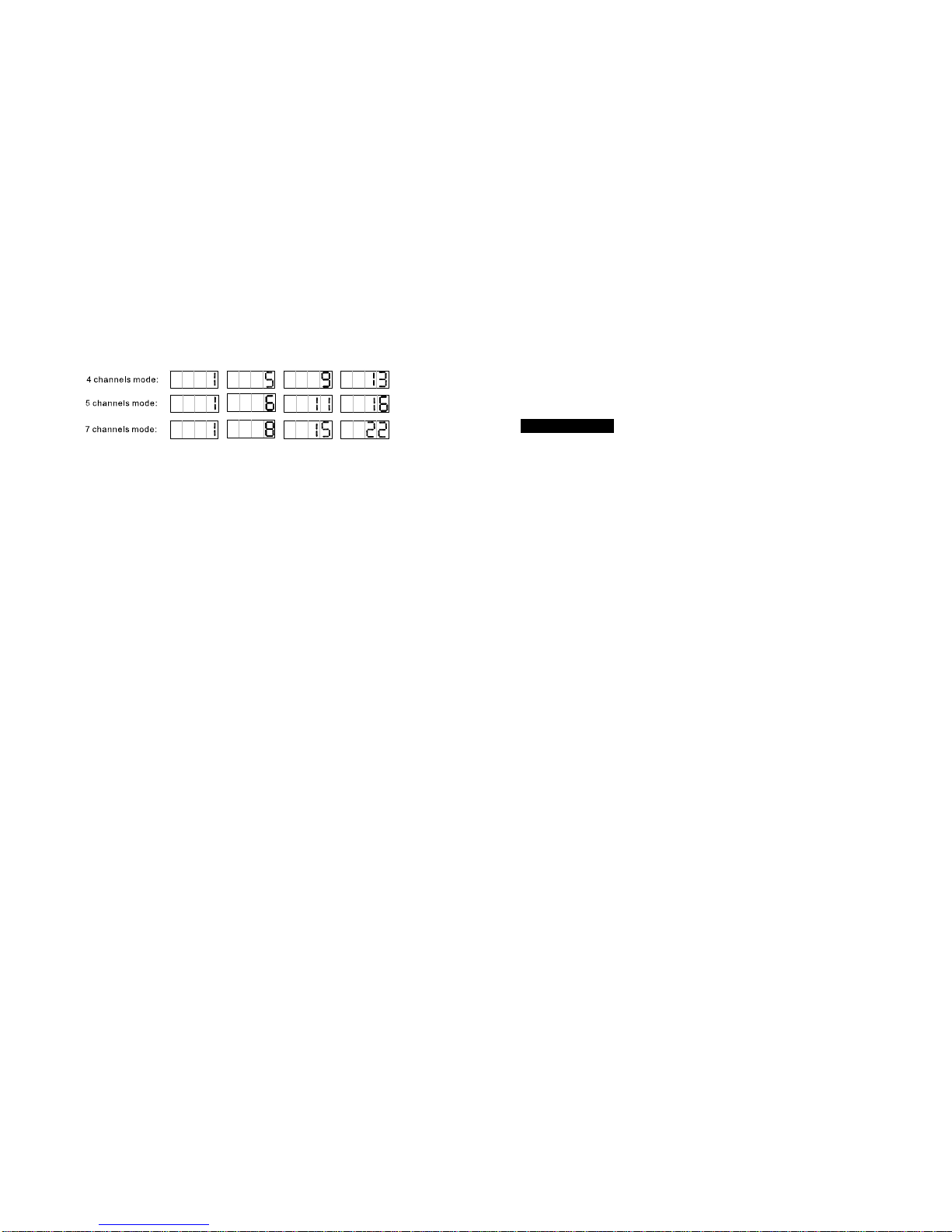
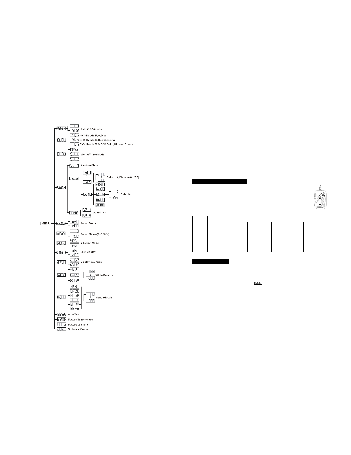
DMX 512 Address
Select the , press the ENTER button and the display will blink. Use the DOWN and UP
button to change the DMX 512 address. Once the address has been selected, press the
ENTER button to setup or automatically exit menu mode without any change after one minute.
Back to the previous functions without any change press the MENU button.
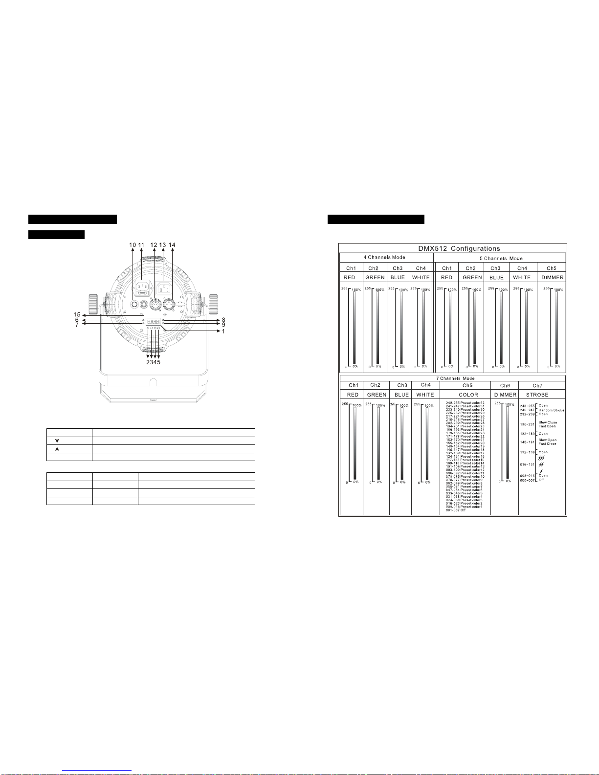
Channel Mode
Select the , press the ENTER button and the display will blink. Use the DOWN and UP
button to select the (4 channels: Red, Green, Blue and White), (5 channels:
Red, Green, Blue, White and Dimmer) or (7 channels: Red, Green, Blue, White, Color,
Dimmer and Strobe) mode. Once the mode has been selected, press the ENTER button to
setup or automatically exit menu mode without any change after one minute. To go back to
the functions without any change press the MENU button.
Slave Mode
Select the , press the ENTER button and the display will blink. Use the DOWN and UP
button to select the (Master), (Slave 1) or (Slave 2) mode. Once the
mode has been selected, press the ENTER button to setup or automatically return to the main
functions without any change after one minute. To go back to the functions without any
change press the MENU button again.
Show Mode
Select the , press the ENTER button and the display will blink. Use the DOWN and UP
button to select the (Random show) or (color) or (fade).
When you selected the , press the ENTER button, and then use the DOWN and UP
button to select the (Color 1) … (Color 9), press the ENTER button and use
the DOWN and UP button to adjust the brightness intensity from (Dimmer 0) to