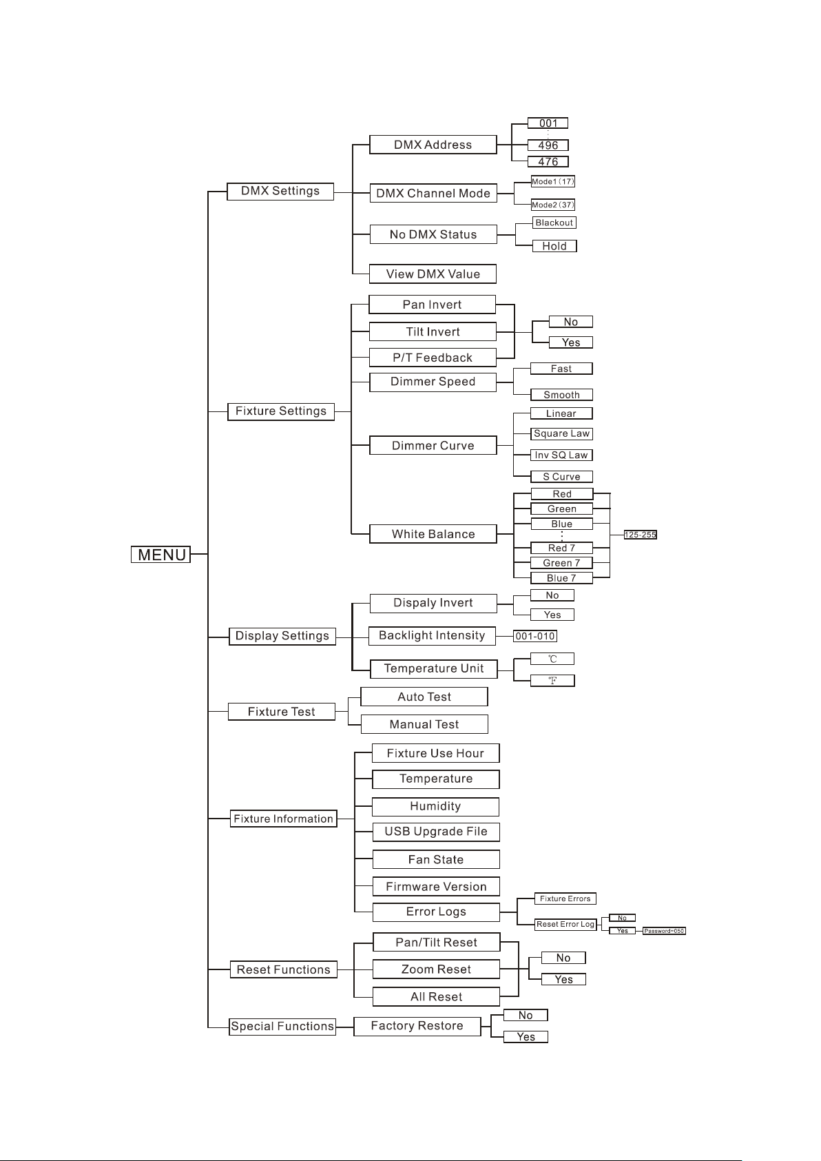
ACME Ozone 3 User manual


CONTENTS
1. Safety Instructions ......................................................................................... 2
2. Technical Specifications ................................................................................. 4
3. How To Set The Unit....................................................................................... 6
3.1 Control Panel ........................................................................................... 6
3.2 Main Function.......................................................................................... 6
3.3 Home Position Adjustment .................................................................... 13
4. Control By Universal DMX Controller ........................................................... 18
4.1 DMX512 Connection.............................................................................. 18
4.2 Address Setting ...................................................................................... 19
4.3 DMX512 Configuration........................................................................... 20
5. Error Information......................................................................................... 28
6. Troubleshooting........................................................................................... 29
7. Fixture Cleaning........................................................................................... 30
1E

1. Safety Instructions
WARNING
Please keep this User Guide for future consultation. If you sell the unit to another user, be sure that
they also receive this instruction manual.
Important:
Damages caused by the disregard of this user manual are not subject to warranty. The dealer will
not accept liability for any resulting defects or problems.
Unpack and check carefully that there is no transportation damage before using the unit.
This product is suitable for indoor use and wet locations. Do not immerse in water.
DO install and operate by qualified operator.
DO NOT allow children to operate the fixture.
Use safety chain when fixing the unit. Handle the unit by carrying its base instead of head only.
The unit must be installed in a location with adequate ventilation, at least 50cm from adjacent
surfaces.
Be sure that no ventilation slots are blocked, otherwise the unit will be overheated.
Before operating, ensure that the voltage and frequency of power supply match the power
requirements of the unit.
It’s important to ground the yellow/green conductor to earth in order to avoid electric shock.
Minimum ambient temperature TA: 0℃. Maximum ambient temperature TA: 40℃.
DO NOT connect the device to any dimmer pack.
During initial start-up some smoke or smell may arise. This is a normal process and does not
necessarily mean that the device is defective, and it will decrease gradually within 15 minutes.
Make sure there are no flammable materials close to the unit while operating to avoid fire
hazard.
Examine the power wires carefully; replace them immediately if there is any damage.
Unit’s surface temperature may reach up to 75℃. DO NOT touch the housing bare-handed
during its operation.
Avoid any inflammable liquids, water or metal objects entering the unit. Once it happens, cut
Please read the instruction carefully which includes important information about
the installation, usage and maintenance.
2E

off the mains power immediately.
DO NOT operate in dirty or dusty environment, do clean fixtures regularly.
DO NOT touch any wire during operation as there might be a hazard of electric shock.
Avoid power wires together twist other cables.
The minimum distance between light output and the illuminated surface must be more than
0.5 meters.
In the event of serious operating problem, stop using the unit immediately.
Never turn on and off the unit time after time.
The housing, the lenses, or the ultraviolet filter must be replaced if they are visibly damaged.
DO NOT open the unit as there are no user serviceable parts inside.
Never try to repair the unit by yourself. Repairs carried out by unskilled people can lead to
damage or malfunction. Please contact the nearest authorized technical assistance center if
needed.
Disconnect the mains power if the fixture is has not been used for a long time.
DO use the original packing materials before transporting it again.
DO NOT look directly at the light while the bulb is on.
DO NOT start on the unit without bulb enclosure or when housing is damaged.
Installation:
The fixture should be mounted via its Omega Quick Release Clamp bracket. Always ensure that the
unit is firmly fixed to avoid vibration and slipping while operating and make sure that the structure
to which you are attaching the unit is secure and is able to support a weight of 10 times of the
fixtures weight. Always use a safety cable that can hold 12 times of the weight of the fixture when
installing.
The equipment must be installed by professionals. It must be installed in a place where is out of the
reach of people and no one can pass by or under it.
3E

2. Technical Specifications
Power Voltage:
AC 100~240V, 50/60Hz
Power Consumption:
370W
Light Source:
7x40W RGBW LED
Zoom Range:
Beam Angle:6°~40°
Field Angle:10°~60°
Dimmer/Shutter:
Smooth dimming from 0-100%; outstanding strobe effect with variable speed
Movement:
Pan: 540°
Tilt: 250°
Pan/Tilt Resolution: 16bit
Control:
DMX Channel: 17/37 Channels
Control Mode: DMX512, RDM
Firmware Upgrade: via DMX link & USB disk
Construction:
Display: LCD Display
Data In/Out: 3-pin IP XLR
Power In/Out: Waterproof Power Connector in/out
Protection Rating: IP65
Features:
Variable CTO
Pixel control, outstanding color macro effect
Motorized liner zoom system
Fast and silent operation; Flicker-free management
Protection Rating: IP65, can be used outdoors all year round
4E

Dimension/Weight:
303x210x457mm, 15.8kgs
11.9"x8.3"x18"in, 34.8lbs
Photometric Diagram:
5E

3. How To Set The Unit
3.1 Control Panel
1. Display: To show the various menus and the selected function
2. Button:
MENU
To enter into move backward or leave the menu
UP
To go backward to move up in the menu
DOWN
To go forward to move down in the menu
ENTER
To perform the desired functions
3. DMX IN: DMX512 link, use 3-pin XLR cable to link the unit and DMX controller
4. DMX OUT: DMX512 link, use 3-pin XLR cable to link the next units
5. FIRMWARE UPGRADE
6. POWER IN: To connect to supply power
7. POWER OUT: To connect to the next fixture
3.2 Main Function
Turn on the unit, press the MENU button into menu mode, and press the UP/DOWN button until
the required function is shown on the monitor. Select the function by the ENTER button. Use the
UP/DOWN button to choose the submenu, press the ENTER button to store and automatically
return to the last menu. Press the MENU button or let the unit idle 30 seconds to exit menu mode.
The screen will be automatically locked if there is no operation for a long time, and can be unlocked
by long-pressing the MENU button.
The main functions are shown below:
6E

7E

DMX Settings
To select DMX Settings, press the ENTER button to confirm, use the UP/DOWN button to select
DMX Address, DMX Channel Mode, No DMX Status or View DMX Value.
DMX Address
To select DMX Address, press the ENTER button to confirm. Use the UP/DOWN button to adjust the
address from 001 to 496/4 7 6, press the ENTER button to store. Press the MENU button back to the
last menu or let the unit idle 30 seconds to exit menu mode.
DMX Channel Mode
To select DMX Channel Mode, press the ENTER button to confirm. Use the UP/DOWN button to
select Mode1 (17) or Mode2 (37), press the ENTER button to store. Press the MENU button back to
the last menu or let the unit idle 30 seconds to exit menu mode.
No DMX Status
To select No DMX Status, press the ENTER button to confirm. Use the UP/DOWN button to select
Blackout(fixture blacks out if DMX signal stops) or Hold(fixture continues to obey the last command
it received Via DMX if DMX signal stops), press the ENTER button to store. Press the MENU button
back to the last menu or let the unit idle 30 seconds to exit menu mode.
View DMX Value
To select View DMX Value, press the ENTER button to confirm. Use the UP/DOWN button to view
the DMX channel value. Press the MENU button back to the last menu or let the unit idle 30
seconds to exit menu mode.
Fixture Settings
To select Fixture Settings, press the ENTER button to confirm, use the UP/DOWN button to select
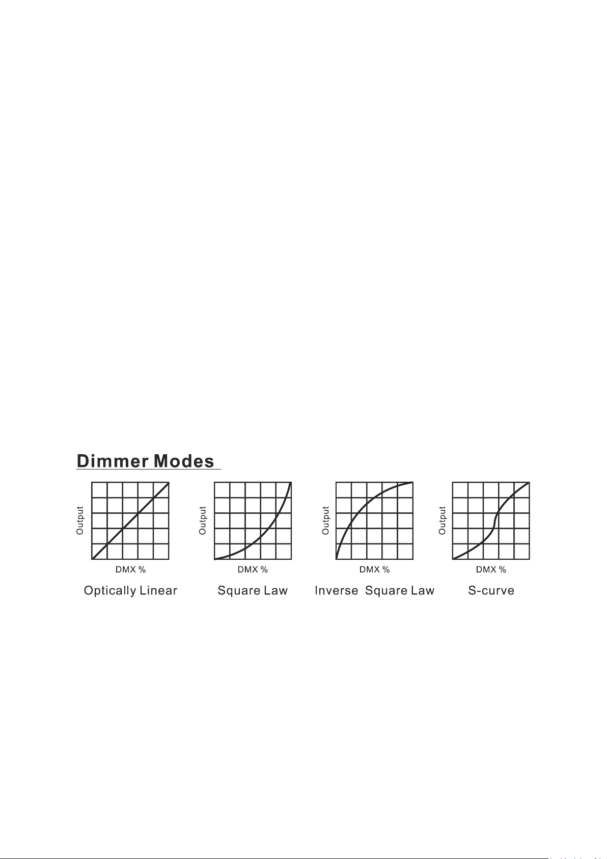
Pan Invert, Tile Invert, P/T Feedback, Dimmer Speed, Dimmer Curve or White Balance.
Pan Invert
To select Pan Invert, press the ENTER button to confirm. Use the UP/DOWN button to select
No(normal) or Yes(pan invert), press the ENTER button to store. Press the MENU button back to the
last menu or let the unit idle 30 seconds to exit menu mode.
8E

Tilt Invert
To select Tilt Invert, press the ENTER button to confirm. Use the UP/DOWN button to select
No(normal) or Yes(tilt invert), press the ENTER button to store. Press the MENU button back to the
last menu or let the unit idle 30 seconds to exit menu mode.
P/T Feedback
To select P/T Feedback, press the ENTER button to confirm. Use the UP/DOWN button to select
No(Pan or tilt’s position will not feedback while out of step) or Yes(Feedback while pan/tilt out of
step), press the ENTER button to store. Press the MENU button back to the last menu or let the unit
idle 30 seconds to exit menu mode.
Dimmer Speed
To select Dimmer Speed, press the ENTER button to confirm. Use the UP/DOWN button to select
Fast or Smooth, press the ENTER button to store. Press the MENU button back to the last menu or
let the unit idle 30 seconds to exit menu mode.
Dimmer Curve
To select Dimmer Curve, press the ENTER button to confirm. Use the UP/DOWN button to select
Linear, Square law, Inv SQ law or S Curve, press the ENTER button to store. Press the MENU button
back to the last menu or let the unit idle 30 seconds to exit menu mode.
Mode 1(Optically Linear):
The increase in light intensity appears to be linear as DMX value is increased.
Mode 2(Square Law):
Light intensity control is finer at low levels and coarser at high levels.
Mode 3(Inverse Square Law):
Light intensity control is coarser at low levels and finger at high levels.
Mode 4(S-Curve):
Light intensity control is finger at low levels and high levels and coarser at medium levels.
9E

White Balance
To select White Balance, press the ENTER button to confirm. Use the UP/DOWN button to select
Red, Green, Blue, Red1, Green1, Blue1,……Red7, Green7, Blue7, press the ENTER button to store.
Use the UP/DOWN button to adjust the value from 125 to 255, press the ENTER button to store.
Press the MENU button back to the last menu or let the unit idle 30 seconds to exit menu mode.
Display Settings
To select Display Settings, press the ENTER button to confirm, use the UP/DOWN button to select
Display Invert, Backlight Intensity or Temperature Unit.
Display Invert
Select Display Invert, press the ENTER button to confirm. Use the UP/DOWN button to select
No(normal display) or Yes(invert display), press the ENTER button to store. Press the MENU button
back to the last menu or let the unit idle 30 seconds to exit menu mode.
Backlight Intensity
Select Backlight Intensity, press the ENTER button to confirm. Use the UP/DOWN button to adjust
the value from 001 to 010, press the ENTER button to store. Press the MENU button back to the last
menu or let the unit idle 30 seconds to exit menu mode.
Temperature Unit
Select Temperature Unit, press the ENTER button to confirm. Use the UP/DOWN button to
select
℃
or
℉
, press the ENTER button to store. Press the MENU button back to the last menu or
let the unit idle 30 seconds to exit menu mode.
F ixture Test
To select Fixture Test, press the ENTER button to confirm, use the UP/DOWN button to select Auto
Test or Manual Test.
Auto Test
Select Auto Test, press the ENTER button to confirm, the unit will run built-in programs to
automatically test. Press the MENU button back to the last menu or exit menu mode after auto test.
10E

Manual Test
Select Manual Test, press the ENTER button to confirm. Use the UP/DOWN button to select channel
Pan, Pan Fine, Tilt, Tilt Fine, Zoom, Spe Func, Dimmer, Shutter, Red, Green, Blue, White, CTO, Color,
Pixel or Pixel Rotating, press the ENTER button to confirm, then use the UP/DOWN button to adjust
the value, press the ENTER button to store, the fixture will run as the channel value indicates. Press
the MENU button back to the last menu or exit menu mode idling 30 seconds.
(All channels value will become 0 after exiting Manual Test menu)
Fixture Information
To select Fixture Information, press the ENTER button to confirm, use the UP/DOWN button to
select Fixture Use Hour, Temperature, Humidity, USB Upgrade File, Fan State, Firmware Version
or Error Logs.
Fixture Use Hour
Select Fixture Use Hour, press the ENTER button to confirm, fixture use hour will show on the
display, press the MENU button to exit.
Temperature
Select Temperature, press the ENTER button to confirm, fixture temperature will show on the
display, press the MENU button to exit.
Humidity
Select Humidity,press the ENTER button to confirm, fixture humidity will show on the display, press
the MENU button to exit.
USB Upgrade File
Select USB Upgrade File, press the ENTER button to confirm, USB upgrade file will show on the
display, press the MENU button to exit.
Fan State
Select Fan State, press the ENTER button to confirm, fixture fan state will show on the display, press
the MENU button to exit.
Firmware Version
Select Firmware Version, press the ENTER button to confirm, firmware version will show on the
display, press the MENU button back to exit.
11E

Error Logs
To select Error Logs, press the ENTER button to confirm. Use the UP/DOWN button to select Fixture
Errors or Reset Error Log, press the ENTER button to store. To select Reset Error Log, press the
ENTER button to confirm, use the UP/DOWN button to select No or Yes, press the ENTER button to
store. To select Yes, press the ENTER button to confirm, use the UP/DOWN button to set the
password 050, press the ENTER button to reset error log. Press the MENU button back to the last
menu or let the unit idle 30 seconds to exit menu mode.
Reset Functions
To select Reset Functions, press the ENTER button to confirm, use the UP/DOWN button to select
Pan/Tilt Reset, Zoom Reset or All Reset.
Pan/Tilt Reset
Select Pan/Tilt Reset, press the ENTER button to confirm. Use the UP/DOWN button to select No or
Yes, press the ENTER button to store. Press the MENU button back to the last menu or let the unit
idle 30 seconds to exit menu mode.
Zoom Reset
Select Zoom Reset, press the ENTER button to confirm. Use the UP/DOWN button to select No or
Yes, press the ENTER button to store. Press the MENU button back to the last menu or let the unit
idle 30 seconds to exit menu mode.
All Reset
Select All Reset, press the ENTER button to confirm. Use the UP/DOWN button to select No or Yes,
press the ENTER button to store. Press the MENU button back to the last menu or let the unit idle
30 seconds to exit menu mode.
Special Functions
Factory Restore
Select Factory Restore,press the ENTER button to confirm. Use the UP/DOWN button to select
No(normal) or Yes(the fixture will reset to factory settings), press ENTER button to store. Press the
MENU button to exit.
12E

RDM FUNCTIONS
Select the MANUFACTURER menu to display the manufacturer of the fixture.
Select the SOFTWARE VERSION menu and the program version number of the fixture will be
displayed.
Select the DMX START ADDRESS menu to change the DMX 512 address (001-512).
Select the DEVICE MODEL DESCRIPTION menu to display the model of the fixture.
Select the DEVICE LABEL menu to change the model of the fixture.
Select the DMX PERSONALITY menu to set the channel mode of the fixture (17/3 7 channel).
Select the DMX PERSONALITY DESCRIPTION menu to display the current channel mode of the
fixture.
Select the DEVICE HOURS menu to display the running time of the fixture.
Select the PAN INVERT menu and the fixture will run the pan invert mode.
Select the TILT INVERT menu and the fixture will run the tilt invert mode.
Select the RESET DEVICE menu, the WARM RESET/COLD RESET option will be displayed. When
WARM RESET is selected, the fixture will start a warm reset, and exit when COLD RESET is selected.
3.3 Home Position Adjustment
Press the MENU button into menu mode, then press theENTER button for about 3 seconds into
offset mode to adjust the home position. Select the function by the ENTER button. Use the
UP/DOWN button to choose the submenu, press the ENTER button to store and automatically
return to the last menu. Press MENU button to exit.
13E

Pan
Enter offset mode, Select Pan, press the ENTER button to confirm, the present position will blink on
the display, use the UP/DOWN button to offset the value from -128 to 127, press the ENTER button
to store. Press the MENU button to exit.
Tilt
Enter offset mode, Select Tilt, press the ENTER button to confirm, the present position will blink on
the display, use the UP/DOWN button to offset the value from -128 to 127, press the ENTER button
to store. Press the MENU button to exit.
Zoom
Enter offset mode, Select Zoom, press the ENTER button to confirm, the present position will blink
on the display, use the UP/DOWN button to offset the value from -128 to 127, press the ENTER
button to store. Press the MENU button to exit.
14E

Red1
Enter offset mode, Select Red1, press the ENTER button to confirm, the present position will blink
on the display, use the UP/DOWN button to offset the value from 20 to 1000, press the ENTER
button to store. Press the MENU button to exit.
Red2
Enter offset mode, Select Red2, press the ENTER button to confirm, the present position will blink
on the display, use the UP/DOWN button to offset the value from 20 to 1000, press the ENTER
button to store. Press the MENU button to exit.
Red3
Enter offset mode, Select Red3, press the ENTER button to confirm, the present position will blink
on the display, use the UP/DOWN button to offset the value from 20 to 1000, press the ENTER
button to store. Press the MENU button to exit.
Red4
Enter offset mode, Select Red4, press the ENTER button to confirm, the present position will blink
on the display, use the UP/DOWN button to offset the value from 20 to 1000, press the ENTER
button to store. Press the MENU button to exit.
Red5
Enter offset mode, Select Red5, press the ENTER button to confirm, the present position will blink
on the display, use the UP/DOWN button to offset the value from 20 to 1000, press the ENTER
button to store. Press the MENU button to exit.
Red6
Enter offset mode, Select Red6, press the ENTER button to confirm, the present position will blink
on the display, use the UP/DOWN button to offset the value from 20 to 1000, press the ENTER
button to store. Press the MENU button to exit.
Red7
Enter offset mode, Select Red7, press the ENTER button to confirm, the present position will blink
on the display, use the UP/DOWN button to offset the value from 20 to 1000, press the ENTER
button to store. Press the MENU button to exit.
Green1
Enter offset mode, Select Green1, press the ENTER button to confirm, the present position will blink
on the display, use the UP/DOWN button to offset the value from 20 to 1000, press the ENTER
button to store. Press the MENU button to exit.
15E

Green2
Enter offset mode, Select Green2, press the ENTER button to confirm, the present position will blink
on the display, use the UP/DOWN button to offset the value from 20 to 1000, press the ENTER
button to store. Press the MENU button to exit.
Green3
Enter offset mode, Select Green3, press the ENTER button to confirm, the present position will blink
on the display, use the UP/DOWN button to offset the value from 20 to 1000, press the ENTER
button to store. Press the MENU button to exit.
Green4
Enter offset mode, Select Green4, press the ENTER button to confirm, the present position will blink
on the display, use the UP/DOWN button to offset the value from 20 to 1000, press the ENTER
button to store. Press the MENU button to exit.
Green5
Enter offset mode, Select Green5, press the ENTER button to confirm, the present position will blink
on the display, use the UP/DOWN button to offset the value from 20 to 1000, press the ENTER
button to store. Press the MENU button to exit.
Green6
Enter offset mode, Select Green6, press the ENTER button to confirm, the present position will blink
on the display, use the UP/DOWN button to offset the value from 20 to 1000, press the ENTER
button to store. Press the MENU button to exit.
Green7
Enter offset mode, Select Green7, press the ENTER button to confirm, the present position will blink
on the display, use the UP/DOWN button to offset the value from 20 to 1000, press the ENTER
button to store. Press the MENU button to exit.
Blue1
Enter offset mode, Select Blue1, press the ENTER button to confirm, the present position will blink
on the display, use the UP/DOWN button to offset the value from 20 to 1000, press the ENTER
button to store. Press the MENU button to exit.
Blue2
Enter offset mode, Select Blue2, press the ENTER button to confirm, the present position will blink
on the display, use the UP/DOWN button to offset the value from 20 to 1000, press the ENTER
button to store. Press the MENU button to exit.
16E

Blue3
Enter offset mode, Select Blue3, press the ENTER button to confirm, the present position will blink
on the display, use the UP/DOWN button to offset the value from 20 to 1000, press the ENTER
button to store. Press the MENU button to exit.
Blue4
Enter offset mode, Select Blue4, press the ENTER button to confirm, the present position will blink
on the display, use the UP/DOWN button to offset the value from 20 to 1000, press the ENTER
button to store. Press the MENU button to exit.
Blue5
Enter offset mode, Select Blue5, press the ENTER button to confirm, the present position will blink
on the display, use the UP/DOWN button to offset the value from 20 to 1000, press the ENTER
button to store. Press the MENU button to exit.
Blue6
Enter offset mode, Select Blue6, press the ENTER button to confirm, the present position will blink
on the display, use the UP/DOWN button to offset the value from 20 to 1000, press the ENTER
button to store. Press the MENU button to exit.
Blue7
Enter offset mode, Select Blue7, press the ENTER button to confirm, the present position will blink
on the display, use the UP/DOWN button to offset the value from 20 to 1000, press the ENTER
button to store. Press the MENU button to exit.
White1
Enter offset mode, Select White1, press the ENTER button to confirm, the present position will blink
on the display, use the UP/DOWN button to offset the value from 20 to 1000, press the ENTER
button to store. Press the MENU button to exit.
White2
Enter offset mode, Select White2, press the ENTER button to confirm, the present position will blink
on the display, use the UP/DOWN button to offset the value from 20 to 1000, press the ENTER
button to store. Press the MENU button to exit.
White3
Enter offset mode, Select White3, press the ENTER button to confirm, the present position will blink
on the display, use the UP/DOWN button to offset the value from 20 to 1000, press the ENTER
button to store. Press the MENU button to exit.
17E

White4
Enter offset mode, Select White4, press the ENTER button to confirm, the present position will blink
on the display, use the UP/DOWN button to offset the value from 20 to 1000, press the ENTER
button to store. Press the MENU button to exit.
White5
Enter offset mode, Select White5, press the ENTER button to confirm, the present position will blink
on the display, use the UP/DOWN button to offset the value from 20 to 1000, press the ENTER
button to store. Press the MENU button to exit.
White6
Enter offset mode, Select White6, press the ENTER button to confirm, the present position will blink
on the display, use the UP/DOWN button to offset the value from 20 to 1000, press the ENTER
button to store. Press the MENU button to exit.
White7
Enter offset mode, Select White7, press the ENTER button to confirm, the present position will blink
on the display, use the UP/DOWN button to offset the value from 20 to 1000, press the ENTER
button to store. Press the MENU button to exit.
4. Control By Universal DMX Controller
4.1 DMX512 Connection
18E

1. At last unit, the DMX cable has to be terminated with a terminator. Solder a 120-o h m 1/4 W
resistor between pin 2(DMX-) and pin 3(DMX+) into a 3-pin XLR-plug and plug it in the DMX-output
of the last unit.
2. Connect the unit together in a “daisy chain” by XLR plug cable from the output of the unit to
the input of the next unit. The cable cannot be branched or split to a “Y” cable. DMX 512 is a very
high-speed signal. Inadequate or damaged cables, soldered joints or corroded connectors can easily
distort the signal and shut down the system.
3. The DMX output and input connectors are pass-through to maintain the DMX circuit, when one
of the units’ power is disconnected.
4. Each lighting unit needs to have a DMX address to receive the data by the controller. The
address number is between 1-512.
5. The end of the DMX 512 system should be terminated to reduce signal errors.
6. 3 pin XLR connectors are more popular than 5 pins XLR.
3 pin XLR: Pin 1: GND, Pin 2: Negative signal (-), Pin 3: Positive signal (+)
5 pin XLR: Pin 1: GND, Pin 2: Negative signal (-), Pin 3: Positive signal (+), Pin4, Pin5 not used.
4.2 Address Setting
If you use a universal DMX controller to control the units, you have to set DMX address from 1 to
512 so that the units can receive DMX signal.
Press the MENU button to enter menu mode, select DMX Settings, press the ENTER button to
confirm, use the UP/DOWN button to select DMX Address, press the ENTER button to confirm, the
present address will blinking the display, use the UP/DOWN button to adjust the address from 001
to 512, press the ENTER button to store. Press the MENU button back to the last menu or idling let
the unit idle 30 seconds to exit menu mode.
Please refer to the following diagram to address your DMX512 channel for the first 4 units.
Channel mode
Unit 1
Address
Unit 2
Address
Unit 3
Address
Unit 4
Address
17 channels 1 18 35 52
37 channels 1 38 75 112
19E
This manual suits for next models
1
Table of contents
Other ACME Lighting Equipment manuals

ACME
ACME Colortec 250 User manual

ACME
ACME Stag Par MP-200 User manual

ACME
ACME Xperior 700SZ Spot User manual

ACME
ACME Theatre Spot 150m User manual

ACME
ACME Thunderroar User manual

ACME
ACME RAYZOR HYBRID User manual

ACME
ACME Thunder User manual

ACME
ACME BOOTES User manual

ACME
ACME Inferno User manual

ACME
ACME BRIGHT User manual

ACME
ACME LED-212RGB User manual

ACME
ACME LED-SC25 User manual

ACME
ACME LED-PS10D RGBW User manual

ACME
ACME Energy Spot PRO User manual

ACME
ACME LIGHT PANEL 1000 User manual

ACME
ACME PEXEL 100 User manual

ACME
ACME Spartan Hybrid C User manual

ACME
ACME FLANDINA 22 IP User manual

ACME
ACME Solaris User manual

ACME
ACME SABER HYBRID PRO User manual