AFL FOCIS WiFi2 User manual

FOCIS WiFi2
Fiber Optic Connector Inspection System
User Guide
www.AFLglobal.com or (800) 321-5298, (603) 528-7780
Test & Inspection

2
Safety Information. . . . . . . . . . . . . . . . . . . . . . . . . . . . . . . . . . . . . . . . . . 4
Standards Compliance Information. . . . . . . . . . . . . . . . . . . . . . . . . . . . . 5
General Information
FOCIS WiFi2 Probe and FOCIS WiFi2 App Solution Overview . . . . . . . . . . . . . . 6
FOCIS WiFi2 Fiber Optic Connector Inspection System . . . . . . . . . . . . . . . . . . . 6
FOCIS WiFi2 App. . . . . . . . . . . . . . . . . . . . . . . . . . . . . . . . . . . . . . . . . . . . . . . 6
Warranty Terms and Conditions. . . . . . . . . . . . . . . . . . . . . . . . . . . . . . . . . . . . 6
Repair Services . . . . . . . . . . . . . . . . . . . . . . . . . . . . . . . . . . . . . . . . . . . . . . . . 6
FOCIS WiFi2 Probe Overview
FOCIS WiFi2 Controls and Interfaces . . . . . . . . . . . . . . . . . . . . . . . . . . . . . . . . 7
Powering Up/Down . . . . . . . . . . . . . . . . . . . . . . . . . . . . . . . . . . . . . . . . . . . . . 7
Multifunctional Button Operation . . . . . . . . . . . . . . . . . . . . . . . . . . . . . . . . . . 8
Multifunctional LED Indicator States . . . . . . . . . . . . . . . . . . . . . . . . . . . . . . . . 8
Battery Charging and Operation . . . . . . . . . . . . . . . . . . . . . . . . . . . . . . . . . . . 9
Configuring FOCIS WiFi2 Probe to Auto-Off . . . . . . . . . . . . . . . . . . . . . . . . . . 9
Properly Installing and Removing Adapter Tips . . . . . . . . . . . . . . . . . . . . . . . . 10
FOCIS WiFi2 App Overview
Downloading FOCIS WiFi2 App . . . . . . . . . . . . . . . . . . . . . . . . . . . . . . . . . . . . 11
Connecting the FOCIS WiFi2 to a Smart Device . . . . . . . . . . . . . . . . . . . . . . . . 11
Mobile Device Screen Format. . . . . . . . . . . . . . . . . . . . . . . . . . . . . . . . . . . . . . 12
Supported Touch Screen Gestures . . . . . . . . . . . . . . . . . . . . . . . . . . . . . . . . . . 12
Live Image Mode . . . . . . . . . . . . . . . . . . . . . . . . . . . . . . . . . . . . . . . . . . . 13
Live Image Screen Features . . . . . . . . . . . . . . . . . . . . . . . . . . . . . . . . . . . . . . . 13
Main Menu . . . . . . . . . . . . . . . . . . . . . . . . . . . . . . . . . . . . . . . . . . . . . . . . 14
Main Menu Overview . . . . . . . . . . . . . . . . . . . . . . . . . . . . . . . . . . . . . . . . . . . 14
Auto Focus . . . . . . . . . . . . . . . . . . . . . . . . . . . . . . . . . . . . . . . . . . . . . . . . . 14
Auto Save . . . . . . . . . . . . . . . . . . . . . . . . . . . . . . . . . . . . . . . . . . . . . . . . . . 14
Pass/Fail . . . . . . . . . . . . . . . . . . . . . . . . . . . . . . . . . . . . . . . . . . . . . . . . . . . 15
Beeper . . . . . . . . . . . . . . . . . . . . . . . . . . . . . . . . . . . . . . . . . . . . . . . . . . . . 15
Auto-Power Off. . . . . . . . . . . . . . . . . . . . . . . . . . . . . . . . . . . . . . . . . . . . . . 15
Language . . . . . . . . . . . . . . . . . . . . . . . . . . . . . . . . . . . . . . . . . . . . . . . . . . 15
Report Settings . . . . . . . . . . . . . . . . . . . . . . . . . . . . . . . . . . . . . . . . . . . . . . 16
Result Manager. . . . . . . . . . . . . . . . . . . . . . . . . . . . . . . . . . . . . . . . . . . . . . 16
Last Image . . . . . . . . . . . . . . . . . . . . . . . . . . . . . . . . . . . . . . . . . . . . . . . . . 16
Import. . . . . . . . . . . . . . . . . . . . . . . . . . . . . . . . . . . . . . . . . . . . . . . . . . . . . 16
Device Info . . . . . . . . . . . . . . . . . . . . . . . . . . . . . . . . . . . . . . . . . . . . . . . . . 16
©2017 AFL , all rights reserved. FWF2-00-1000 Revision AA, 2017-12-20
Table of Contents

3
Captured Image Mode . . . . . . . . . . . . . . . . . . . . . . . . . . . . . . . . . . . . . . . 17
Captured Image Views . . . . . . . . . . . . . . . . . . . . . . . . . . . . . . . . . . . . . . . . . . 17
Fiber Image View . . . . . . . . . . . . . . . . . . . . . . . . . . . . . . . . . . . . . . . . . . . . 18
Pass/Fail Results Table View . . . . . . . . . . . . . . . . . . . . . . . . . . . . . . . . . . . . 19
Image Information View . . . . . . . . . . . . . . . . . . . . . . . . . . . . . . . . . . . . . . . 20
Pass/Fail Criteria . . . . . . . . . . . . . . . . . . . . . . . . . . . . . . . . . . . . . . . . . . . 21
Pass/Fail Screen Features. . . . . . . . . . . . . . . . . . . . . . . . . . . . . . . . . . . . . . . . . 21
IEC, IPC, AT&T Pass/Fail Analysis . . . . . . . . . . . . . . . . . . . . . . . . . . . . . . . . . . . 22
Example IEC Rule . . . . . . . . . . . . . . . . . . . . . . . . . . . . . . . . . . . . . . . . . . . . 22
Configuring Pass/Fail Criteria. . . . . . . . . . . . . . . . . . . . . . . . . . . . . . . . . . . . . . 23
Enable/Disable Pass/Fail Analysis. . . . . . . . . . . . . . . . . . . . . . . . . . . . . . . . . 23
Select Rule . . . . . . . . . . . . . . . . . . . . . . . . . . . . . . . . . . . . . . . . . . . . . . . . . 23
View Rule . . . . . . . . . . . . . . . . . . . . . . . . . . . . . . . . . . . . . . . . . . . . . . . . . . 23
Edit User Rule:. . . . . . . . . . . . . . . . . . . . . . . . . . . . . . . . . . . . . . . . . . . . . . . 24
Result Manager . . . . . . . . . . . . . . . . . . . . . . . . . . . . . . . . . . . . . . . . . . . . 26
Result Manager Screen . . . . . . . . . . . . . . . . . . . . . . . . . . . . . . . . . . . . . . . . . . 26
To access the Result Manager . . . . . . . . . . . . . . . . . . . . . . . . . . . . . . . . . . . 26
Screen Features. . . . . . . . . . . . . . . . . . . . . . . . . . . . . . . . . . . . . . . . . . . . . . 26
Creating a New Job/Cable Folder. . . . . . . . . . . . . . . . . . . . . . . . . . . . . . . . . . . 27
Renaming a Job/Cable/Fiber . . . . . . . . . . . . . . . . . . . . . . . . . . . . . . . . . . . . . . 28
Saving Test Results . . . . . . . . . . . . . . . . . . . . . . . . . . . . . . . . . . . . . . . . . . . . . 29
Saving Test Results for the First Time. . . . . . . . . . . . . . . . . . . . . . . . . . . . . . 29
Saving Test Results to a New Job/Cable Folder . . . . . . . . . . . . . . . . . . . . . . 30
Saving Test Results to an Existing Job/Cable Folder . . . . . . . . . . . . . . . . . . . 31
Result Manager Functionality . . . . . . . . . . . . . . . . . . . . . . . . . . . . . . . . . . . . . 32
To Select a Single Item - Job/Cable/Fiber . . . . . . . . . . . . . . . . . . . . . . . . . . 32
To View Saved Test Result . . . . . . . . . . . . . . . . . . . . . . . . . . . . . . . . . . . . . . 32
To Select Multiple Items - Jobs, Cables, Fibers . . . . . . . . . . . . . . . . . . . . . . . 32
To Delete Saved Test Results . . . . . . . . . . . . . . . . . . . . . . . . . . . . . . . . . . . . 33
Sharing Captured Test Results . . . . . . . . . . . . . . . . . . . . . . . . . . . . . . . . . . . 34
Inspecting Fibers with FOCIS WiFi2 Solution . . . . . . . . . . . . . . . . . . . . . 35
Table of Contents

4
Safety Information
IMPORTANT! Proper care in handling should be taken when using any precision optical test
equipment. Scratched or contaminated optical connectors can impact the performance of the instrument.
NOTE! FOCIS WiFi2 contains no user serviceable parts. This instrument must be returned to AFL or
authorized agents for repair.
IMPORTANT! It is important to keep connector end-faces on the launch and receive cables and those
on the Fiber Under Test (FUT) clean, to ensure accurate measurements and operation.
CAUTION! Never view a live ber. Never look directly into the optical outputs of ber optic network
equipment, test equipment, patch cords and jumpers. Laser radiation is harmful to eyes.
WARNING! Use only the specied AC adapter. Use of another type of AC adapter can damage the
instrument and create the danger of re and electrical shock.
WARNING! To avoid the danger of re and electrical shock:
• Never use a voltage that is different from that for which the AC adapter is rated.
• Do not plug the unit into a power outlet that is shared by other devices.
• Never modify the power cord or excessively bend, twist, or pull it.
• Do not allow the power cord to become damaged. Do not place heavy objects on the power cord or
expose it to heat.
• Never touch the AC adapter while your hands are wet.
• Should the power cord become seriously damaged (internal wiring exposed or shorted), contact the
manufacturer to request servicing.
NOTE! Refer to your company’s safety procedures when working with optical systems.
NOTE! Follow your company’s approved cleaning procedures.

5
AFL Test & Inspection FOCIS WiFi2 contains a WiFi transceiver.
FCC ID: 2ANTH-FWF2R1-2F
IC ID: 23261-FWF2R12F
NOTE: This equipment has been tested and found to comply with the limits of Part 15 of the FCC Rules.
These limits are designed to provide reasonable protection against harmful interference in a residential
installation. This equipment generates, uses and can radiate radio frequency energy and, if not installed
and used in accordance with the instructions, may cause harmful interference to radio communications.
However, there is no guarantee that interference will not occur in a particular installation. If this
equipment does cause harmful interference to radio or television reception, which can be determined
by turning the equipment off and on, the user is encouraged to try to correct the interference by one or
more of the following measures:
• Reorient or relocate the receiving antenna.
• Increase the separation between the equipment and receiver.
• Connect the equipment into an outlet on a circuit different from that to which the receiver is
connected.
• Consult the dealer or an experienced radio/TV technician for help.
ISED RF Exposure Guidance Statement:
• In order to comply with FCC/ISED RF Exposure requirements, this device must be installed to provide
at least 20 cm separation from the human body at all times.
• An de se conformer aux exigences d’exposition RF FCC / ISED, cet appareil doit être installé pour
fournir au moins 20 cm de séparation du corps humain en tout temps.
NOTE: The AFL FOCIS WiFi2 complies with Industry Canada RSS 247 standard. See RSS GEN 7.1.5. The
term “IC:” before the certication/registration number only signies that registration was performed
based on a Declaration of Conformity indicating that Industry Canada technical specications were
met. The term “IC:” before the certication/registration number does not imply that Industry Canada
approved the equipment.
Le FOCIS WiFi2 d’AFL est conforme à la norme d’Industrie Canada RSS 247. Voir RSS GEN 7.1.5. Le
terme “IC:” avant le numéro de certication/enregistrement signie seulement que l’enregistrement
a été effectué sur la base d’une déclaration de conformité indiquant que les spécications techniques
d’Industrie Canada ont été rencontrées. Le terme “IC:” avant le numéro de certication/enregistrement
n’implique pas qu’Industrie Canada a approuvé l’équipement.
ISED RSS Notice:
This device complies with Industry Canada’s licence-exempt RSSs. Operation is subject to the following
two conditions:
1. This device may not cause interference;
2. This device must accept any interference, including interference that may cause undesired operation
of the device.
Le présent appareil est conforme aux CNR d’Industrie Canada applicables aux appareils radio exempts
de licence. L’exploitation est autorisée aux deux conditions suivantes:
1. l’appareil ne doit pas produire de brouillage;
2. l’appareil doit accepter tout brouillage radioélectrique subi, même si le brouillage est susceptible
d’en compromettre le fonctionnement.
Standards Compliance Information

6
FOCIS WiFi2 Probe and FOCIS WiFi2 App Solution Overview
Warranty Terms and Conditions
Paired with AFL's FOCIS WiFi2 Fiber Optic Connector Inspection System, FOCIS WiFi2 App features a
complete ber optic connector inspection and data management solution.
FOCIS WiFi2 Fiber Optic Connector Inspection System
FOCIS WiFi2 is an ergonomic Fiber Optic Connector Inspection System that, when paired with an iOS
or Android smart device, provides fast and accurate IEC/IPC/AT&T compliant and user-dened Pass/Fail
end-face cleanliness analysis. Free of charge iOS and Android companion Apps support a comprehensive
and user-friendly feature set.
Pass/fail results in seconds: With the press of a single button, FOCIS WiFi2 auto-focuses, captures,
centers and analyzes the end-face image to industry standard IEC 61300-3-35 (2015), IPC-8497-1,
AT&T TP-76461 and user-dened criteria.
Untethered operation: App-based report generator with results/reports transferable to the aeRos
cloud. With rechargeable battery and convenient Pass/Fail LED feedback, FOCIS WiFi2 can be used
autonomously.
Wide range of adapter tips: Interchangeable adapter tips support single and multi-ber connector
inspection for a wide range of patch cords and bulkhead-mounted connectors having either PC/UPC or
APC polished end-faces.
FOCIS WiFi2 App
By pairing the FOCIS WiFi2 inspection probe with the FOCIS WiFi2 App, users are enabled to control their
test hardware directly from their Android or iOS smart devices.
FOCIS WiFi2 App is available via Google play store or Apple Store.
General Information
USA Repair and Calibration services
AFL Test & Inspection Division
16 Eastgate Park Road
Belmont, NH 03220
603-528-7780
800-321-5298
AFL Test and Inspection products are warranted against defective material and workmanship for a period
of (1) one year from the date of delivery to the end user. Optional Extended Warranty starts at the end
of the standard (1) one year warranty period. Any product that is found defective within the warranty
period, will (at the discretion of AFL) be repaired or replaced. Warranty will be voided if the product has
been repaired or altered by other than an authorized AFL repair facility or when it has been subjected to
misuse, negligence, or accident.
In no case shall AFL liabilities exceed the original purchase price.
Repair Services
Please contact customer service for a return authorization number prior to sending your AFL test
equipment in for repair or calibration.
7
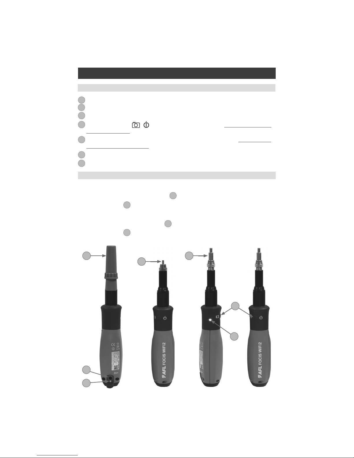
FOCIS WiFi2 Probe Overview
1. Dust cover.
2. Optical inspection port.
3. Adapter tip.
4. Multifunctional button / has several multiplexed functions. See “Multifunctional Button
Operation” on page 8.
5. Multifunctional LED indicator represents various states of the FOCIS WiFi2. See “Multifunctional
LED Indicator States” on page 8.
6. 5 VDC input jack.
7. Charging indicator.
1
2
3
4
5
6
7
FOCIS WiFi2 Controls and Interfaces
Powering Up/Down
2
31
6
7
4
5
Power-Up
• Press and release the Multifunctional button
4
to turn the FOCIS WiFi2 probe On.
• LED status indicator
5
will display Flashing Blue light.
Power-Down
• Press and hold the Multifunctional button
3
for over 3 seconds to turn the probe Off.
• LED status indicator
4
will turn off.
8
FOCIS WiFi2 Probe Overview
Multifunctional LED indicator
B
represents various states of the FOCIS WiFi2 as follows:
# Action State LED Color/Behavior
1 FOCIS WiFi2 power On Firmware loading Blue blinks 3 times:
1 s On/1 s Off
2 Press FOCIS WiFi2 button
3-5 times
Upgrade mode, loading Firmware Blue blinks:
0.5 s On/0.5 s Off
3 Firmware ashing Firmware Flashing. After ashing
FOCIS WiFi2 enter to Firmware
loaded.
Blue blinks
0.2 s On/0.2 s Off
4 FOCIS WiFi2 power On Firmware loaded. WiFi SSID beacon,
not connected.
Blue blinks:
2 s On/1 s Off
5 Smart device WiFi connect WiFi connected, Apps not active White lit steadily
6 Smart device WiFi
disconnect
WiFi disconnected, WiFi SSID beacon Blue blinks:
2 s On/1 s Off
7 Apps start Live mode Blue lit steadily
8 Apps closed/standby WiFi connected, Apps not active White lit steadily
9 Image capture and Analysis Pass Green lit steadily
10 Image capture and Analysis Fail Red lit steadily
11 Image capture and Analysis No Fiber Cyan lit steadily
12 Image capture without
Analysis, Menu
Not Analyzed, Menu Purple lit steadily
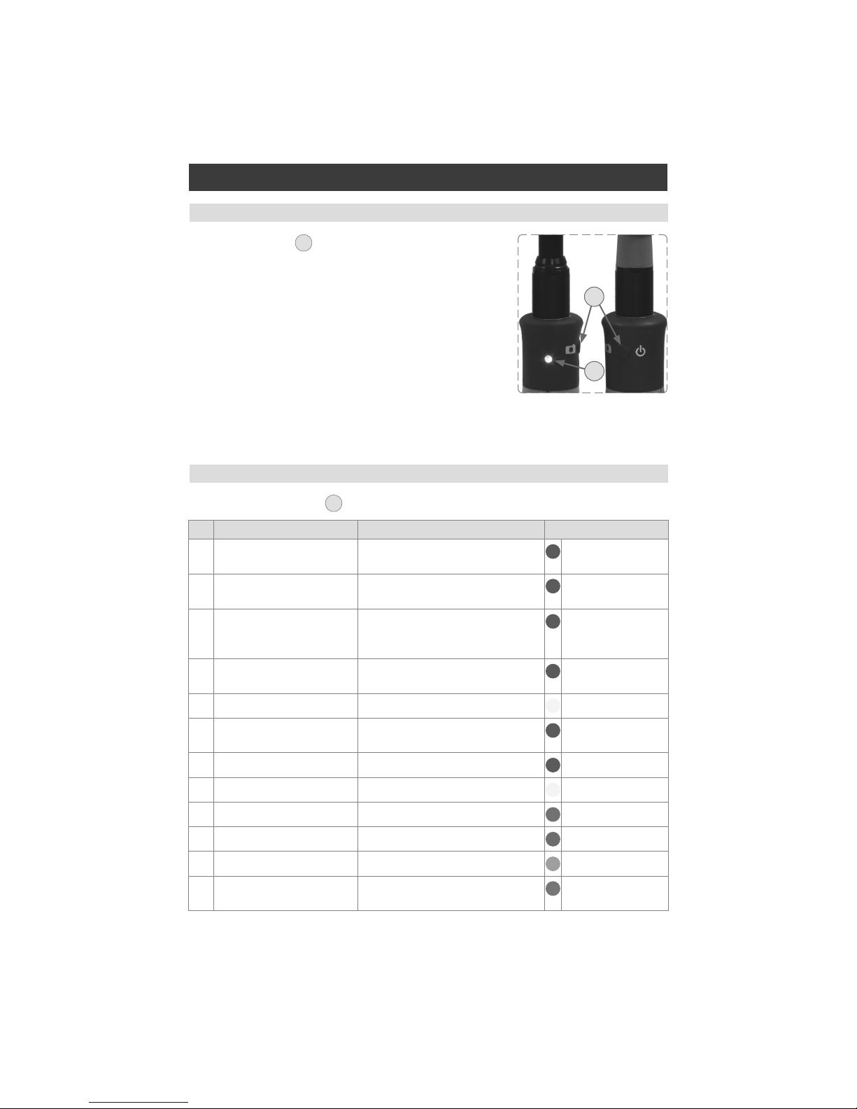
Multifunctional Button Operation
Multifunctional LED Indicator States
Multifunctional button
A
has several multiplexed functions:
• Powers FOCIS WiFi2 On/Off.
• In the Live Image mode, press the Multifunctional button to
perform the following:
–Auto Focus image (if the Auto Focus option is enabled)
–Capture the displayed image and enter the Captured
Image mode
–Analyze image (if the Pass/Fail option is enabled)
–Save results and in the memory of WiFi connected Smart
Device (if Auto Save is enabled)
• In the Captured Image mode, press the Multifunctional
button to return to the Live Image mode.
B
A

9
FOCIS WiFi2 Probe Overview
To charge battery of the FOCIS WiFi2 probe:
1. Plug the included AC Charger into AC outlet.
2. Connect charger plug into 5 VDC jack
A
on the FOCIS WiFi2 probe.
3. Charging indicator
B
displays the battery charging status as follows:
LED Color/Behavior Battery Charging Status
Off AC is not connected
Red Battery is charging
Green Battery is fully charged
Red/Green flashing Charging error:
• Verify that correct 5VDC 2A charger is used.
• Allow the FOCIS WiFi2 probe to cool before charging.
4. FOCIS WiFi2 probe charges while operating.
Battery Charging and Operation
B
Configuring FOCIS WiFi2 Probe to Auto-Off
FOCIS WiFi2 probe Power Save options are controlled by iOS & Android Apps.
The following instructions assume that FOCIS WiFi2 probe is connected to a smart device, which
operates in the FOCIS WiFi2 App.
On your Smart Device:
1. From the Live Mode screen, tap on the Menu on-screen button to display the Main Menu.
2. From the Main Menu, tap Auto-Power Off.
3. Select the desired power save option: 1 min, 5 min, 30 min, Never.
1
2
3
2
A
3
1
10
FOCIS WiFi2 Probe Overview
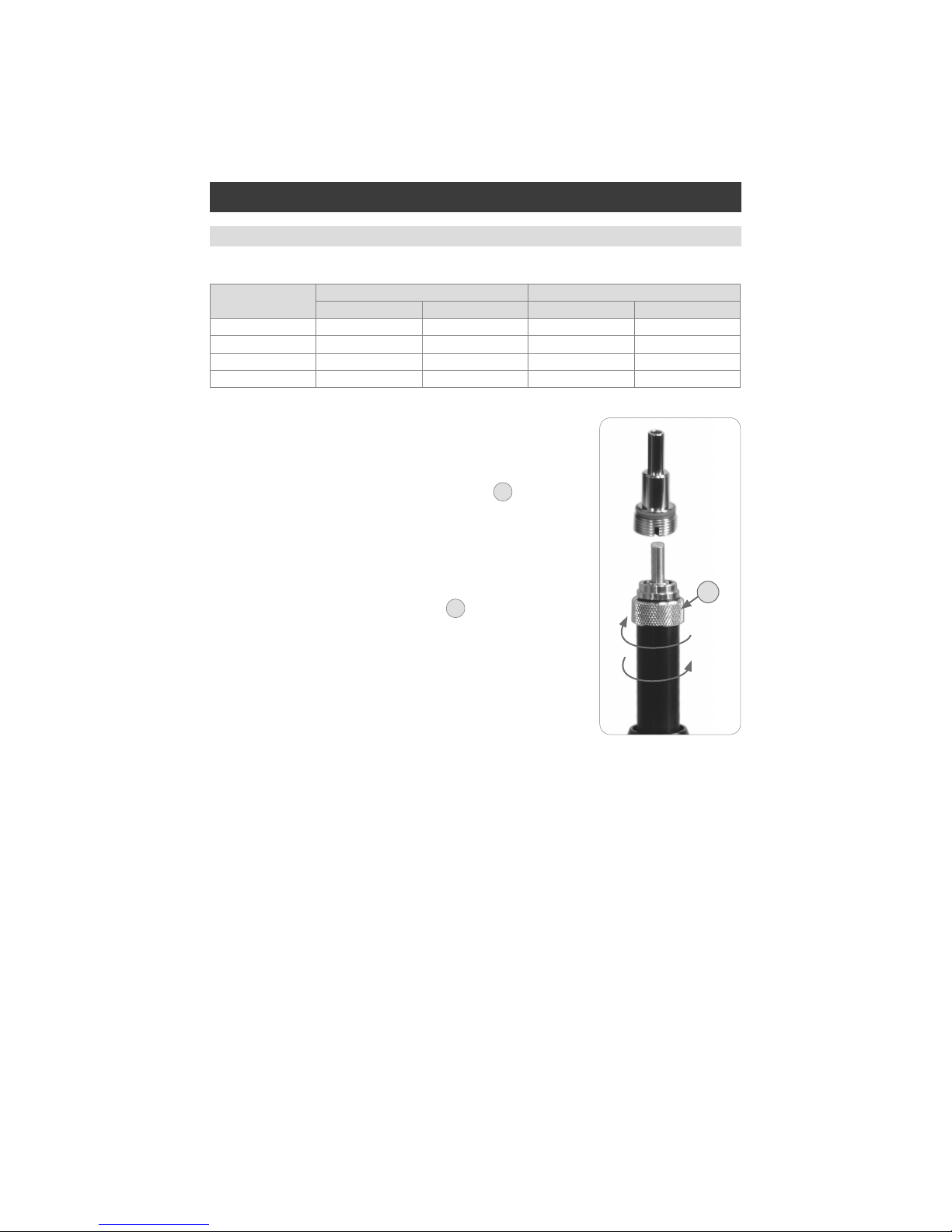
Properly Installing and Removing Adapter Tips
Note: Contact AFL Sales Representative or Tech Support for additional
connector adapter tips
Installing Adapter Tips
• While holding adapter tip in place, raise captive nut
A
until it
engages with adapter tip threads.
• Turn captive nut counter-clockwise (viewed from front/top).
• Hand-tighten (do not over-tighten).
Removing Adapter Tips
Probe tips are held in place with a captive nut
A
.
• Turn captive nut clockwise (viewed from front/top).
• Continue until captive nut is free of adapter tip.
• Remove adapter tip by pulling it gently straight off the probe base.
FOCIS WiFi2 is available with the following adapter tips:
Connector UPC Connectors APC Connectors
Ferrule Bulkhead Ferrule Bulkhead
SC FFLX-01-U25 FFLX-01-SC FFLX-01-A25 FFLX-01-ASC
FC FFLX-01-U25 FFLX-01-FC FFLX-01-A25 FFLX-01-AFC
LC FFLX-01-U125 FFLX-01-LC FFLX-01-A125 FFLX-01-ALC2
ST FFLX-01-U25 FFLX-01-ST Not applicable Not applicable
A
Tighten
Loosen

11
Downloading FOCIS WiFi2 App
FOCIS WiFi2 App Overview
Download FOCIS WiFi2 App from Google Play or Apple Store.
Connecting the FOCIS WiFi2 to a Smart Device
On FOCIS WiFi2 probe:
• Press and release the / button to power On.
• LED status indicator will display Flashing Blue light indicating that FOCIS WiFi2 is in “WiFi Beacon
Mode” – ready to connect to your smart device.
On your Smart Device:
• Navigate to Settings.
• Tap Wi-Fi
A
. Make sure Wi-Fi is turned on
B
.
• Locate your FOCIS WiFi2 device (as in example screen below -
C
); tap.
• Enter password: 12345678
D
.
• Tap Connect
E
.
• Note the ‘Connected’ status
F
.
• Your FOCIS WiFi2 probe is now connected to your smart device.
D
E
C
On FOCIS WiFi2 probe:
• Note that LED status indicator changes to White indicating that FOCIS WiFi2 is connected; FOCIS
WiFi2 App is not active.
• Launch the FOCIS WiFi2 App on your smart device.
• Note that LED status indicator changes to Blue indicating that FOCIS WiFi2 is connected and FOCIS
WiFi2 App is active in Live Mode.
F
B
A

12
Mobile Device Screen Format
FOCIS WiFi2 App supports vertical and horizontal screen formats. Switching from vertical format to
horizontal is performed by turning the mobile device vertically/horizontally.
Note: ‘Screen Rotation’ feature needs to be enabled in the mobile device Settings menu.
FOCIS WiFi2 App User Interface Overview
The FOCIS WiFi2 App display is controlled from the touch screen of the mobile device using a supported
set of gestures
Touch Gesture Description Function Screens
Tap
Briey touch surface with ngertip
Select All screens
Double tap
Rapidly touch surface twice with
ngertip
Enter edit mode Captured Image,
Drag
Move ngertip over surface
without losing contact
Pan, scroll Live Image,
Captured Image
Flick/Swipe
Quickly brush surface with
ngertip
Switching modes Captured Image
Pinch
Touch surface with two ngers
and bring them closer together
Zoom out Live Image,
Captured Image
Spread
Touch surface with two ngers
and move them apart
Zoom in Live Image,
Captured Image
Supported Touch Screen Gestures
13
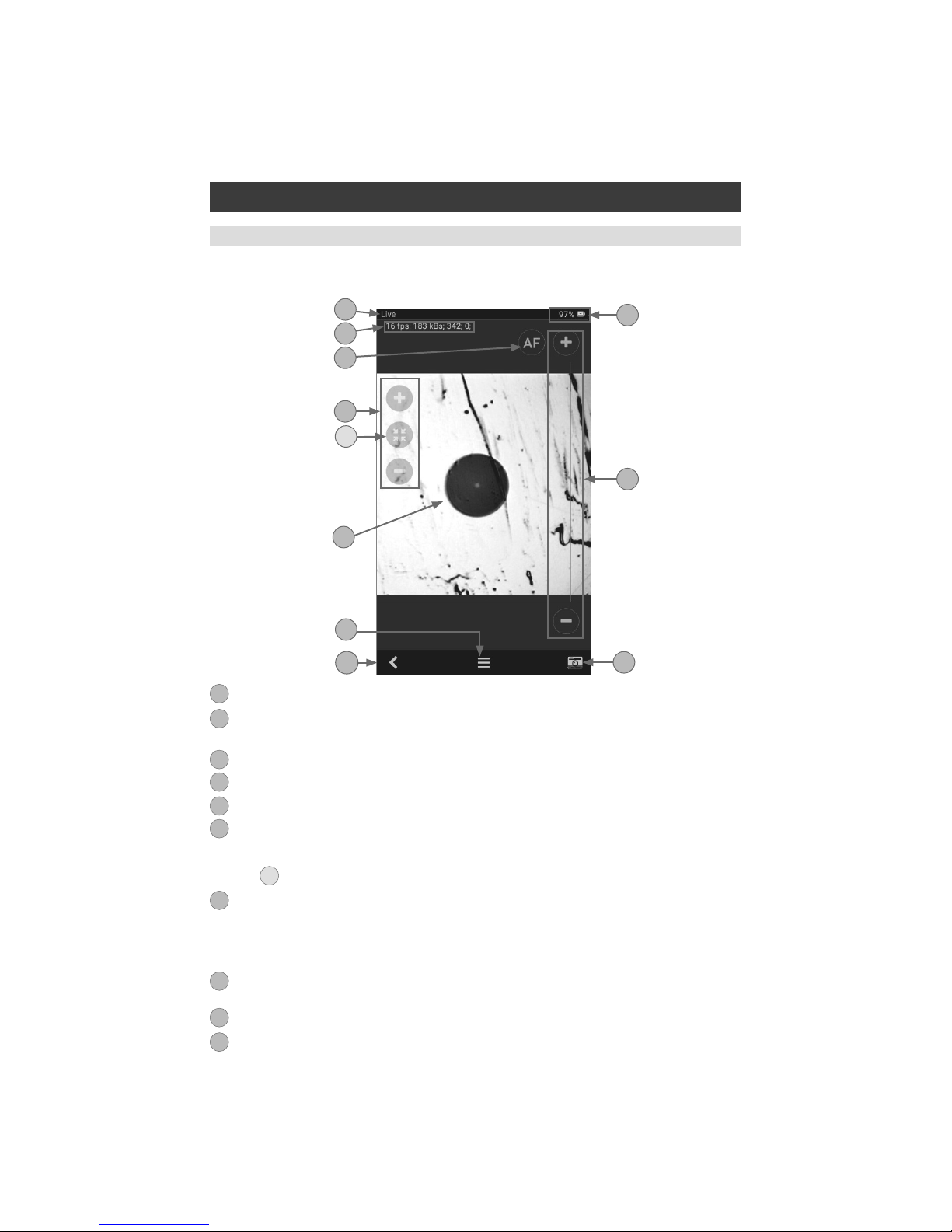
FOCIS WiFi2 App starts in the Live Image mode, which enables the user to view live images of a ber
end-face and perform visual inspection of the displayed ber end-face image on a mobile device.
Live Image Screen Features
1
2
10
4
3
9
6
7
5
8
1. Screen title: Indicates that FOCIS WiFi2 operates are in the Live image mode.
2. Live video streaming status: This row indicates frame per second data and kB/s transfer rate,
focus position and signature for auto focusing.
3. Battery status field: indicates percentage of battery charge.
4. AF (auto-focus) control: Tap to initiate auto-focus.
5. Focus control slider: Drag Focus slider or tap ( + ) / ( – ) to increase/decrease focal length.
6. Zoom controls:
• Tap ( + ) / ( – ) for increasing/decreasing the scale of the live ber-end image.
• Tap
A
to reset the nominal Zoom.
7. Live image of the ber that is being inspected.
• The ber image can be scaled and positioned on the screen by pinching/spreading/dragging the
displayed ber image.
• Tapping on the ber image will turn ON/Off the Focus and Zoom control buttons.
8. Menu on-screen button: Tapping Menu displays the Main Menu that allows the user to set
preferences, manage saved test results and perform other non-test functions.
9. Capture on-screen button: Tap to initiate Image capture and enter the Capture screen.
10. Back on-screen button: Tap to return to the previous screen.
1
2
3
4
5
6
7
8
9
10
A
Live Image Mode

14
1
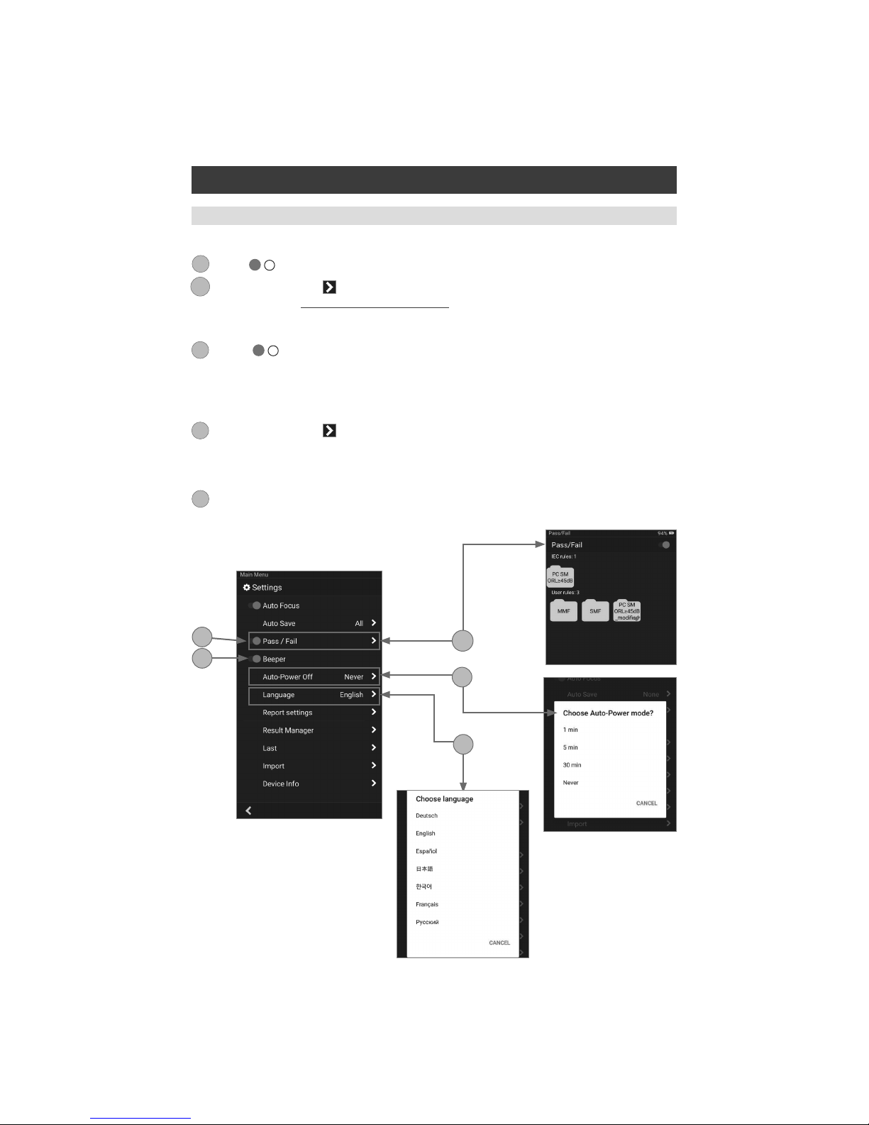
The Main Menu is accessed from Live Image mode by tapping the Menu on-screen button. Main
Menu contains various Settings that are used to select user preferences, perform general settings,
manage saved test results, and perform other non-test functions.
The Main Menu screen contains the following controls:
• / (On/Off) -Tapping this control enables/disables the selected Setting.
• Right arrow - Tapping this control will either display a pop-up menu or a sub-screen allowing to
congure the selected Setting.
• Back on-screen button - Tap this control to return to the previous screen - Live Image mode.
The Main Menu allows conguring Settings as follows:
Auto Focus
1. Tap the / control to enable/disable auto focus.
• If set to On, then pressing the Capture button will automatically focus before capturing an image.
• When set to Off, the ber image will be captured at the current focus position.
Auto Save
2. Tap on the Right arrow to display a pop-up menu
• Choose from the available Auto Save options: All, Pass only, None.
• When Auto Save is enabled, then tapping Capture button from Live Image mode will cause FOCIS
WiFi2 to perform the following:
–Auto Focus (if enabled)
–Capture image
–Perform Pass/Fail Analysis (if enabled)
–Save image and pass/fail results to the congured Job/Cable folder
1
2
Main Menu Overview
Main Menu
2
15
3
4
Main Menu
FOCIS WiFi2 App User Interface Overview
Pass/Fail
1. Tap the / control to enable/disable Pass/Fail Analysis.
2. Tap on the Right arrow to display a sub-screen that allows conguring Pass/Fail Criteria. For
details see section “Pass/Fail Criteria” on page 21.
Beeper
3. Tap the / control to enable/disable a sound signal that indicates Pass/Fail Analysis results.
When enabled, FOCIS WiFi2 will produce High tone beep for Passed results and Low tone beep for
Failed or No Fiber results.
Auto-Power Off
4. Tap on the Right arrow to display a pop-up menu.
• Choose from the available Auto-Power options:1 min, 5 min, 30 min, Never.
Language
5. Select the desired Language option from the list of available options.
3
3A
4
5
6
3A
6
5
16
Main Menu
FOCIS WiFi2 App User Interface Overview
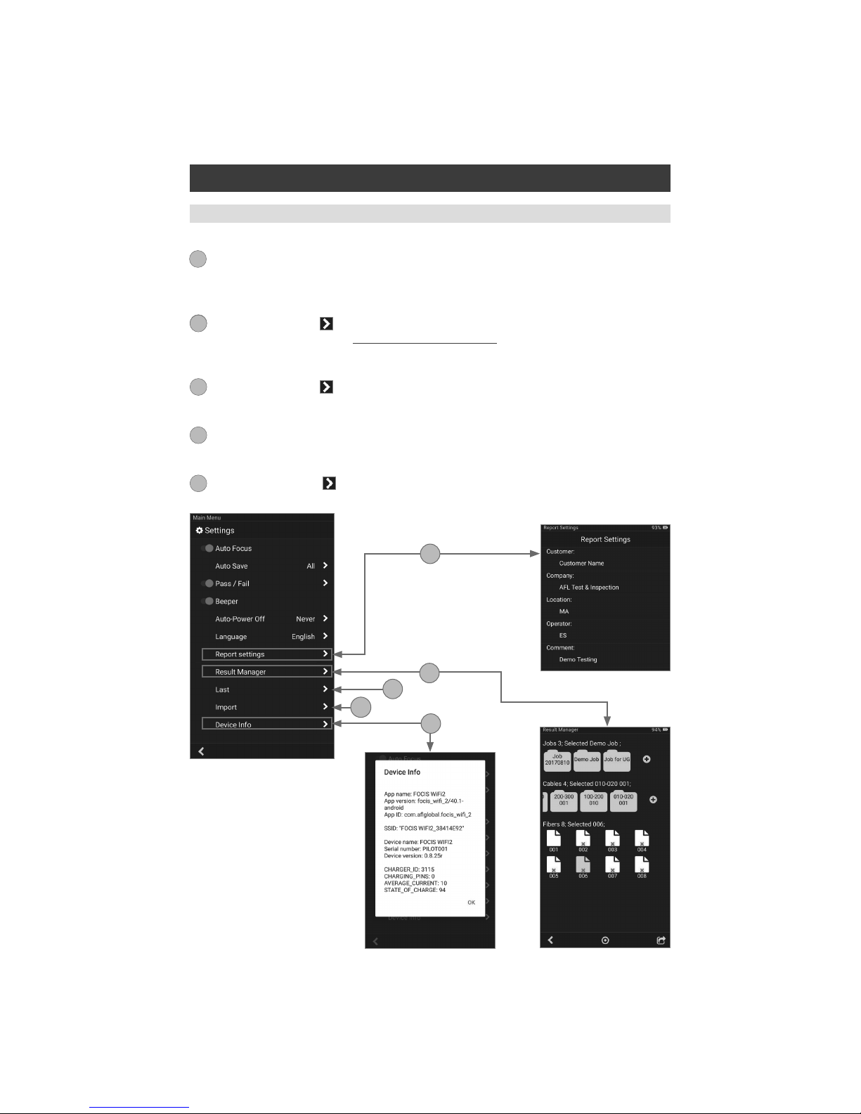
Report Settings
1. Congure reports by adding various data: Customer, Company, Location, Operator, and
Comments. These report settings will be applied to all saved result.
Result Manager
2. Tap on the Right arrow
to display the Result Manager, which allows the user to manage stored
results. For details see section “Result Manager” on page 26.
Last Image
3. Tap on the Right arrow to recall the most recently viewed ber end-face image.
Import
4. Allows the user to import saved ber images from the Photo Gallery.
Device Info
5. Tap on the Right arrow to view Application, WiFi SSID and Device information.
7
8
8
9
10
11
8
7
9
10
11

17
Captured Image Views
Captured Image Mode
AB
Captured Image screen features three Display Views Identied by View Tabs:
1. Fiber Image View identied by Fiber Image Tab - .
2. Pass/Fail Results Table View identied by Pass/Fail Results Table Tab - .
3. Image Information View identied by Image Information Tab - .
Switching between Display Views is done by tapping on the View Tab icon or by swiping the screen to
the left or right. The active Tab icon is displayed on a highlighted in Orange color background - .
1
2
3
Once a ber end-face image has been captured and analyzed (if enabled), inspection test results will be
displayed in the Captured Image screen. Tapping on the displayed ber end-face image allows the user
to switch the display modes sequentially, as follows:
1. Image of the inspected ber end-face with Pass/Fail Analysis overlay (default display mode)
2. Pass/Fail Analysis results only
3. Image of a ber end-face only
A
B
C
C
1 2 3
18
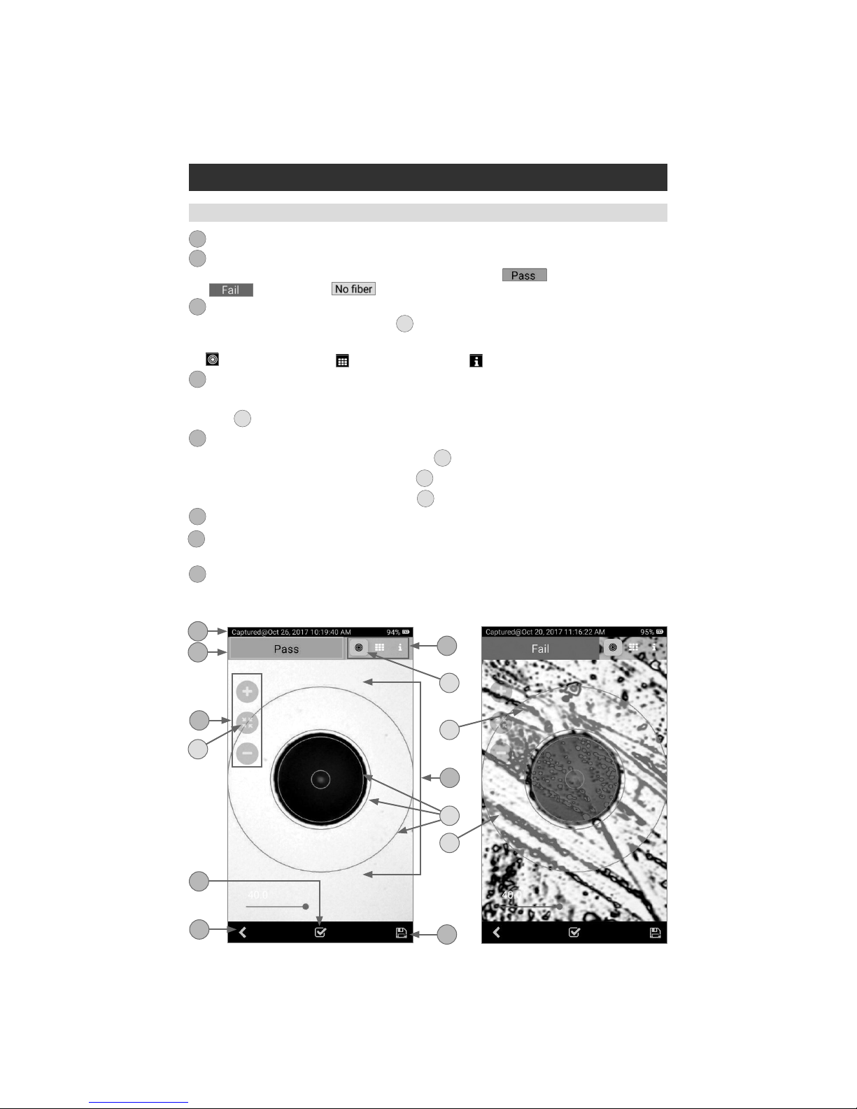
Fiber Image View
Captured Image Mode
1. Screen title: Indicates date and time of the test - [Captured @ hh:mm:ss].
2. Pass/Fail Analysis indication: Shown only if Pass/Fail Analysis option is enabled in the Main
Menu. Depending on performed analysis, this eld will display: for Passing ber,
for Failing ber, if No Fiber detected during Pass/Fail Analysis.
3. Display Tabs icons with the Image tab selected (the active tab icon will is displayed on a
highlighted in Orange color background
A
). Switching between views is done by swiping the
screen to the left or right or by directly taping on the tab icon.
– Fiber End-face Image; – Pass/Fail Results Table; – Image Information
4. Zoom controls:
• Tap ( + ) / ( – ) for increasing/decreasing the scale of the live ber-end image.
• Tap
B
to reset the nominal Zoom.
5. End-face image: displays end-face image with Pass/Fail overlay (if enabled).
• Passing scratches/defects highlighted in GREEN
C
.
• Failing scratches/defects highlighted in RED
D
.
• Analyzed zones represented by BLUE circles
E
.
6. Analyze on-screen button: Tap to perform analysis of defects / scratches.
7. Save on-screen button: Only displayed is Auto Save is disabled in Main Menu. Tap to manually
save captured image and Pass/Fail results (if performed).
8. Back on-screen button: Tap to return to the Live Image mode.
1
2
3
4
5
6
7
8
1
4
87
5
23
B
D
E
C
A
6

19
Pass/Fail Results Table View
1. Screen title: Indicates date and time of the test - [Captured @ hh:mm:ss].
2. Pass/Fail Analysis indication: Shown only if Pass/Fail Analysis option is enabled in the Main
Menu. Depending on performed analysis, this eld will display:
for Passing ber,
for Failing ber, if No Fiber detected during Pass/Fail Analysis.
3. Display Tabs icons with the Pass/Fail display tab selected (the active tab icon will is displayed on
a highlighted in Orange color background
A
). Switching between views is done by swiping the
screen to the left or right or by directly taping on the tab icon.
– Fiber End-face Image; – Pass/Fail Results Table; – Image Information
4. Analysis Rule applied to determine Pass/Fail.
5. Analysis Zones (if enabled): A - core, B - cladding, C - adhesive, D - contact area.
6. Scratch analysis results for each zone:
• Reports the number of detected scratches exceeding limit for each region.
• Highlights failed rules in RED.
7. Defect analysis results for each zone:
• Reports the number of detected defects exceeding limit for each region.
• Highlights failed rules in RED.
8. Analyze on-screen button: Tap to perform analysis of defects/scratches.
9. Save on-screen button: Only displayed is Auto Save is disabled in Main Menu. Tap to manually
save captured image and Pass/Fail results (if performed).
10. Back on-screen button: Tap to return to the Live Image mode.
1
2
3
4
5
6
7
8
9
10
Captured Image Mode
5
10 9
7
1
2
4
3
A
8
6

20
Image Information View
1. Screen title: Indicates date and time of the test - [Captured @ hh:mm:ss].
2. Pass/Fail Analysis indication: shown only if Pass/Fail Analysis option is enabled in the Main
Menu. Depending on performed analysis, this eld will display:
for Passing ber,
for Failing ber, if No Fiber detected during Pass/Fail Analysis.
3. Display Tabs icons with the Image Information display tab selected (the active tab icon will is
displayed on a highlighted in Orange color background
A
). Switching between views is done by
swiping the screen to the left or right or by directly taping on the tab icon.
• – Fiber End-face Image
• – Pass/Fail Results Table
• – Image Information
4. Results ID field: Parameters displayed in this eld Job, Scope End, Far End, Cable, Fiber
identify the directory (Job/Cable/Fiber) into which the inspected ber end-face image and Pass/Fail
Analysis results will be saved.
• Tapping on icon of any parameter in this eld will display the Result Manager screen, which
allows the user to view/change/edit details as needed.
• Tapping on Swap Ends
B
will swap test ends.
5. Time & Date field: indicates Time & Date of the displayed captured image.
6. Rule field: indicates the applied Pass/Fail Analysis rule. Tapping on icon displays the Pass/Fail
Rules screen, which allows the user to view/change/edit Rules.
1
2
3
4
5
6
7. Report Settings: Tap on icon
to customize reports by adding
Customer/Company/Location/Operator
information. Customized report
information will be applied to the
currently captured image only. For
next captured image, will be used
report information dened in the
Menu > Report settings.
8. Analyze on-screen button: Tap to
perform analysis of defects/scratches.
9. Save on-screen button: Only
displayed is Auto Save is disabled in
Main Menu. Tap to manually save
captured image and Pass/Fail results
(if performed).
10. Back on-screen button: Tap to
return to the Live Image mode.
7
8
9
10
Captured Image Mode
5
6
7
10 9
1
2
4
3
A
8
B
Table of contents
Other AFL Test Equipment manuals

AFL
AFL FlexScan FS200 OTDR User manual

AFL
AFL FOCIS Duel User manual

AFL
AFL OPM5 User manual

AFL
AFL M710 Series Installation instructions

AFL
AFL Noyes OPM4-3D User manual

AFL
AFL NOYES OLS Series User manual

AFL
AFL FOCIS Lightning 2 User manual

AFL
AFL FlexScan FS300 User manual

AFL
AFL WDM900 User manual

AFL
AFL OPM Series User manual


Popular Test Equipment manuals by other brands


Infinite
Infinite PE PASTERNACK PE5CK1015 user manual

Keysight Technologies
Keysight Technologies M8000 Series Getting started guide

VOLTCRAFT
VOLTCRAFT 6300SVC operating instructions

Keysight Technologies
Keysight Technologies 85059A Operating and service manual

Spirent
Spirent A1-400-QD-16-T1P installation instructions

Veryx
Veryx PktBlaster installation guide