AFL FOCIS User manual

FOCIS Lightning
Fiber Optic Connector Inspection System
User Guide
www.AFLglobal.com or (800) 321-5298, (603) 528-7780
Test & Inspection

2
Safety Information..........................................4
Standards Compliance Information.............................5
General Information ........................................6
FOCIS Lightning | aeRos®Solution Overview . . . . . . . . . . . . . . . . . . . . . . . . . . 6
FOCIS Lightning Fiber Optic Connector Inspection System ..............6
aeRos .....................................................6
FOCIS Flex App ..............................................6
Made for iPad mini 3 - Legal Notice...............................6
How to View Device Information Menu ..............................7
Warranty Terms and Conditions....................................7
Repair Services ................................................7
Standards Compliance Information .................................7
FOCIS Lightning Overview ....................................8
Controls, Display, Interfaces ......................................8
Getting Started ............................................9
Powering Up/Down .............................................9
Battery Charging and Operation ...................................9
MPO Live Image Mode Overview...................................10
On-screen Indicators ..........................................10
Buttons Functionality .........................................11
Understanding MPO Connector Key Orientation Settings...............12
Understanding Fiber Numbering After The Image Capture..............12
Capture Button Operation ........................................13
Inspecting MPO Connectors ......................................13
Captured MPO Image - Overview Page ..............................14
Detailed View of the Currently Selected Fiber .......................15
Pass/Fail Analysis Details Page ..................................16
Image Information Page .......................................17
Main Menu and Settings .....................................18
Main Menu Overview ...........................................18
Settings Menu Overview . . . . . . . . . . . . . . . . . . . . . . . . . . . . . . . . . . . . . . . . . 18
Capture Settings . . . . . . . . . . . . . . . . . . . . . . . . . . . . . . . . . . . . . . . . . . . . . . . 19
To Enable Auto Focus .........................................19
To Configure Auto-Save and Auto-Send............................19
To Configure ‘Save to’ Destination................................19
Pass/Fail Analysis ..............................................20
IEC Pass/Fail Analysis .........................................20
Example IEC Rule ............................................20
Setting Pass/Fail Criteria .......................................21
Connector Settings .............................................23
©2019 AFL , all rights reserved. FOCIS-LTNG-1000 Revision AA, 2019-04-05
Table of Contents

3
MPO Connector Fiber Configurations Support .......................23
To Configure MPO Connector ...................................24
Configuring Bluetooth ...........................................25
Display & Power Save Settings.....................................25
Set Time and Date..............................................25
Saving Captured Images .....................................26
Saving to the Current Folder ......................................26
Saving to a Newly Created Folder ..................................26
Saving to an Existing Folder.......................................26
Viewing Saved Results (Results Manager) .......................27
Opening Image Files - Reviewing Saved Results........................27
Creating New Jobs/Cables/Files ....................................27
Deleting Jobs/Cables/Files ........................................27
Using FOCIS Lightning with FOCIS Flex App ......................28
Sharing Captured Test Results.................................29
Sending Captured Results to FlexScan ..............................29
Configuring Bluetooth.........................................29
Manually Send Results to FlexScan .................................29
WiFi-based Inspection File Access on FOCIS Lightning..............30
Table of Contents

4
Safety Information
IMPORTANT! Proper care in handling should be taken when using any precision optical test
equipment. Scratched or contaminated optical connectors can impact the performance of the instrument.
NOTE! FOCIS Lightning contains no user serviceable parts. This instrument must be returned to AFL or
authorized agents for repair.
IMPORTANT! To ensure accurate measurements and operation, it is important to keep connector end-
faces on the ber under test clean.
CAUTION! Never view a live ber. Never look directly into the optical outputs of ber optic network
equipment, test equipment, patch cords and jumpers. Laser radiation is harmful to eyes.
WARNING! Use only the specied AC adapter. Use of another type of AC adapter can damage the
instrument and create the danger of re and electrical shock.
WARNING! To avoid the danger of re and electrical shock:
• Never use a voltage that is different from that for which the AC adapter is rated.
• Do not plug the unit into a power outlet that is shared by other devices.
• Never modify the power cord or excessively bend, twist, or pull it.
• Do not allow the power cord to become damaged. Do not place heavy objects on the power cord or
expose it to heat.
• Never touch the AC adapter while your hands are wet.
• Should the power cord become seriously damaged (internal wiring exposed or shorted), contact the
manufacturer to request servicing.
NOTE! Refer to your company’s safety procedures when working with optical systems.
NOTE! Follow your company’s approved cleaning procedures.

5
AFL Test & Inspection FOCIS Lightning contains a WiFi transceiver.
FCC ID: 2ANTH-FLGHTN18
IC: 23261-FLGHTN18
NOTE: This equipment has been tested and found to comply with the limits of Part 15 of the FCC Rules.
These limits are designed to provide reasonable protection against harmful interference in a residential
installation. This equipment generates, uses and can radiate radio frequency energy and, if not installed
and used in accordance with the instructions, may cause harmful interference to radio communications.
However, there is no guarantee that interference will not occur in a particular installation. If this equipment
does cause harmful interference to radio or television reception, which can be determined by turning the
equipment off and on, the user is encouraged to try to correct the interference by one or more of the
following measures:
• Reorient or relocate the receiving antenna.
• Increase the separation between the equipment and receiver.
• Connect the equipment into an outlet on a circuit different from that to which the receiver is connected.
• Consult the dealer or an experienced radio/TV technician for help.
FCC Part 15 Clause 15.21
Changes or modications not expressly approved by the party responsible for compliance could void the
user’s authority to operate the equipment.
ISED RF Exposure Guidance Statement:
• In order to comply with FCC/ISED RF Exposure requirements, this device must be installed to provide at
least 20 cm separation from the human body at all times.
• An de se conformer aux exigences d’exposition RF FCC / ISED, cet appareil doit être installé pour
fournir au moins 20 cm de séparation du corps humain en tout temps.
NOTE: The AFL FOCIS Lightning complies with Industry Canada RSS 247 standard. See RSS GEN 7.1.5.
The term “IC:” before the certication/registration number only signies that registration was performed
based on a Declaration of Conformity indicating that Industry Canada technical specications were met.
The term “IC:” before the certication/registration number does not imply that Industry Canada approved
the equipment.
Le FOCIS Lightning d’AFL est conforme à la norme d’Industrie Canada RSS 247.Voir RSS GEN 7.1.5. Le
terme “IC:” avant le numéro de certication/enregistrement signie seulement que l’enregistrement a été
effectué sur la base d’une déclaration de conformité indiquant que les spécications techniques d’Industrie
Canada ont été rencontrées. Le terme “IC:” avant le numéro de certication/enregistrement n’implique pas
qu’Industrie Canada a approuvé l’équipement.
ISED RSS Notice:
This device complies with Industry Canada’s licence-exempt RSSs. Operation is subject to the following two
conditions:
1. This device may not cause interference;
2. This device must accept any interference, including interference that may cause undesired operation of
the device.
Le présent appareil est conforme aux CNR d’Industrie Canada applicables aux appareils radio exempts de
licence. L’exploitation est autorisée aux deux conditions suivantes:
1. l’appareil ne doit pas produire de brouillage;
2. l’appareil doit accepter tout brouillage radioélectrique subi, même si le brouillage est susceptible d’en
compromettre le fonctionnement.
Standards Compliance Information

6
‘Made for iPad’ means that an electronic accessory has been designed to connect specically to iPod,
iPhone, or iPad, respectively, and has been certied by the developer to meet Apple performance standards.
Apple is not responsible for the operation of this device or its compliance with safety and regulatory standards. Please
note that the use of this accessory with iPod, iPhone, or iPad may affect wireless performance.
–iPad, and Retina are trademarks of Apple Inc., registered in the U.S. and other countries.
–iPad mini is a trademark of Apple Inc., registered in the U.S. and other countries.
–Android is a trademark of Google Inc.
Made for iPad mini 3 - Legal Notice
FOCIS Lightning | aeRos®Solution Overview
AFL’s FOCIS Lightning Fiber Optic Connector Inspection System, paired with AFL’s aeRos cloud
with FOCIS Flex app comprise a complete ber optic connector inspection and workow and data
management solution.
FOCIS Lightning Fiber Optic Connector Inspection System
FOCIS Lightning is a self-contained, compact, and hand-held inspection probe that can be used
independently or paired with AFL's FOCIS Flex app and aeRos cloud. FOCIS Lightning is a self-contained
multi-ber connector inspection probe with integrated screen. It is intended specically for the inspection
of multi-ber connectors and bulkheads such MPO and MTP®including multi-row varieties. The FOCIS
Lightning can perform industry standard and user-dened end-face cleanliness analysis at a rate of
about 1 second per ber. Lightning stores connector level and individual ber images, analysis, overlays,
and zones tables locally and provides both WiFi and Bluetooth wireless links. The AFL FOCIS app (iOS
and Android) provides a comprehensive and user-friendly feature set as well as connectivity with AFL’s
cloud-based aeRos®workow automation platform.
aeRos
aeRos is an open, cloud-based, workow management platform that facilitates two-way communication
and data exchange from engineering to project management to your technician in the eld. Now
everyone has access to test results and can address challenges in real-time. aeRos allows project
managers to send jobs directly to technicians, dening tests and congurations as needed. Throughout
the job, managers can monitor technicians' progress and help to solve problems as they arise. aeRos
solution is available in two options: aeRos BASIC and aeRos PRO:
aeRos®BASIC account — Data Management solution that allows users to save their test data in the
aeRos Cloud and then retrieve it from anywhere at any time with a standard Internet browser. aeRos
BASIC is free to all owners of AFL’s aeRos enable test equipment.
aeRos®PRO account — Workow Management solution that allows users to manage their entire
testing workow and enables seamless and efcient communications and data management. aeRos
PRO is available in annual and lifetime License congurations.
FOCIS Flex App
By pairing the FOCIS Lightning inspection probe with the FOCIS Flex app and aeRos PRO, users are
enabled to control their test hardware directly from their Android or iOS smart devices. With aeRos PRO
account, test projects and setups can be created and predened in aeRos cloud, and then pushed to the
smart device app to simplify the test process for technicians. Technicians receive a notication on their
smart device and can work on scheduled projects. As the project is completed, inspection results are
automatically synchronized with the cloud for instant access, analysis, and reporting.
FOCIS Flex app is available via Google play store or App Store.
General Information
7
Standards Compliance Information
FOCIS Lightning has been designed and tested to comply with the relevant sections of any applicable
specications including full compliance with all essential requirements of the applicable EU Directives.
USA Repair and Calibration services
AFL Test & Inspection Division
16 Eastgate Park Road
Belmont, NH 03220
(603)528-7780
(800)321-5298
ServiceRepair@aglobal.com
https://www.aglobal.com
Warranty Terms and Conditions
AFL Test and Inspection products are warranted against defective material and workmanship for a period
of (1) one year from the date of delivery to the end user. Optional Extended Warranty starts at the end
of the standard (1) one year warranty period. Any product that is found defective within the warranty
period, will (at the discretion of AFL) be repaired or replaced. Warranty will be voided if the product has
been repaired or altered by other than an authorized AFL repair facility or when it has been subjected to
misuse, negligence, or accident.
In no case shall AFL liabilities exceed the original purchase price.
Repair Services
Please contact customer service for a return authorization number prior to sending your AFL test
equipment in for repair or calibration.
General Information
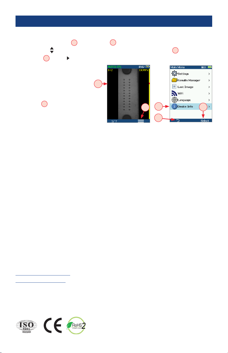
How to View Device Information Menu
• From the Live Image mode A, press the Menu Bbutton to access the Main Menu screen.
• Press Up/Down arrow buttons to navigate and highlight the Device Info menu C.
• Press Select Dor Right arrow button to display a sub-screen of the Device Info menu, which will
display the following Info:
–Device name
–Serial number
–Controller version number
–User Interface version number
• Press Back Ebutton to return to
Live Image mode.
Note: It is helpful to have your FOCIS
Lightning Device Information available if
you need to contact AFL Test & Inspection Customer Service or Technical Support.
A
F
L
T
e
s
t
&
I
n
s
p
e
c
t
i
o
n
B
A
D
C
E
8
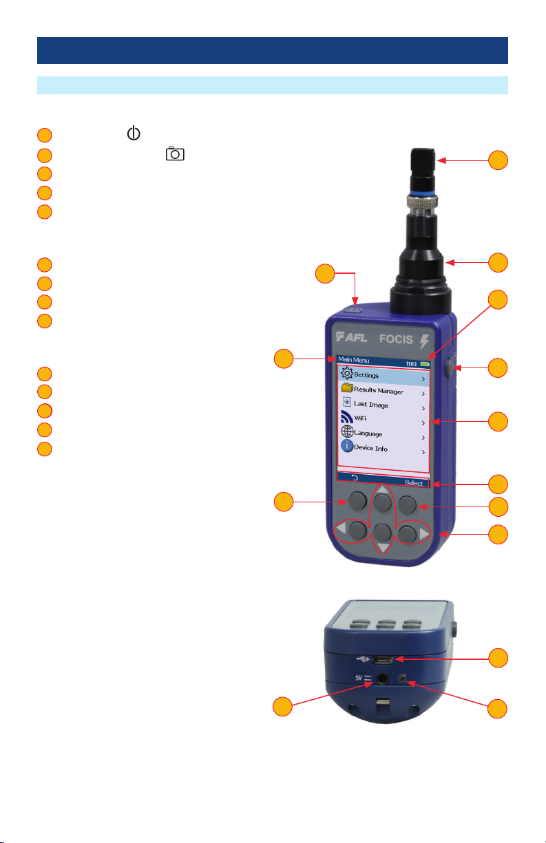
Controls, Display, Interfaces
FOCIS Lightning Overview
Controls
1 Power button -
2 Image Capture button -
3 F1 soft button (typically Back function)
4 F2 soft button (typically Select function)
5 Navigation and Edit functional buttons
Display (2-inch Color LCD [320 x 240])
6 Screen title
7 Battery status icon
8 Image and information display area
9 F1 and F2 soft button labels area
Interfaces
10 Optical inspection port
11 Adapter tip
12 Micro-USB port
13 5 VDC input jack
14 Charging indicator
1
2
3
4
5
6
7
8
9
10
11
12
12
13
14
13
12
14
1
3
62
8
9
7
10
11
4
5

9
Powering Up/Down
Battery Charging and Operation
Getting Started
Power-Up
• Press and release the Power button A.
Power-Down
• Press and hold the Power button Auntil display turns off.
Congure FOCIS Lightning to Auto-Off
• From the Main Menu -> Settings, select
Display & Power Save option.
• Select desired power save option: 2 min, 5 min, 10 min, Never.
A
• Plug the included AC Charger into AC outlet.
• Connect charger plug into 5 VDC jack Bon FOCIS Lightning.
• LED Cindicates charging status as follows:
–OFF - AC not connected
–RED - Charging battery
–GREEN - Fully charged
–RED/GREEN ashing - Charging error. Verify correct
5VDC 2A charger is used. Allow to cool before charging.
• FOCIS Lightning charges while operating.
• Battery icon Dindicates battery state as follows:
- AC connected; charging, not fully charged
- AC connected; charging, fully charged
- Battery operation, fully charged
- Battery operation, partially charged
- <15 min Battery operating time remaining
BC
D

10
MPO Live Image Mode Overview
Getting Started
2 23 3
FOCIS Lightning powers-up in the Live Image mode screen.
Note: Users can always display the Live Image screen (from any other mode/screen) by pressing the
Capture button once or by pressing the Back button enough times.
On-screen Indicators
1 AUTO: ON or AUTO: OFFlabel indicates Auto Focus functionality as set in
Main Menu > Settings > Capture screen A:
–AUTO: ON label is displayed when Auto Focus is enabled –
–AUTO: OFF label is displayed when Auto Focus is disabled –
1
A A
2 Time of day - as set in Main Menu > Settings > Time & Date screen.
3 Battery charge icon indicates battery state, see “Battery Charging and Operation” on page 9.
4 Current Zoom level ID ‘1+2’, ‘1’ or ‘2’ - selected by pressing the 1/? Zoom/Help button B.
5 Up’ or ‘Down’ - Indicate ‘Up’ or ‘Down’ MPO bulkhead alignment sleeve key position. ‘Up’ or
‘Down’ is toggled by pressing the Left arrow button.
6 Zoom/Help button label - numeric value ‘1+2’, ‘1’ or ‘2’ indicates the “next zoom level” settings
7 Menu button label.
2
3
4
5
6
7
5
7 7
44
6 6
5
11
B
11
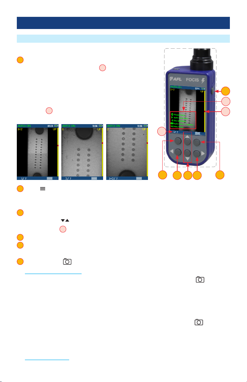
Buttons Functionality
1 1/? Zoom/Help soft button provides several functions:
• Press and hold to display help tips Aabout buttons usage.
• Short press to toggle ‘1+2’ > ‘1’ > ‘2’ zoom levels, where:
–‘1+2’ displays the entire end-face image
–‘1’ displays the upper half of the full end-face image
–‘2’ displays the bottom half of the full end-face image
–Label Babove button indicates the “next zoom” settings
1
MPO Live Image Mode Features
Getting Started
2 Menu Button
• Press to display the Main menu that allows the user to set preferences, manage saved test results
and perform other non-test functions.
3 Up and Down Arrow buttons:
• Press Up/Down arrow buttons to manually adjust focus.
• Vertical ‘slider’ Cindicates the current focus level relative to focus range.
4 Right Arrow button: Press to auto focus once.
5 Left Arrow button: Press to toggle the MPO bulkhead alignment sleeve key position between Up
and Down.
6 Capture Button
In the Live Image mode: Capture button initiates live image capture.
• When the Auto Focus option is enabled in the Capture screen and Capture button is pressed:
–Auto focus is initiated
–Image is captured when auto focus completes
–Image is analyzed if Pass/Fail set to On
–FOCIS Lightning transitions to Captured Image mode
• When the Auto Focus option is disabled in the Setting screen and Capture button is pressed:
–Image is captured (without adjusting focus)
–Image is analyzed if Pass/Fail set to On
–FOCIS Lightning transitions to Captured Image mode
In all other modes: Capture button is used to return to the Live Image mode.
2
3
4
5
6
1+2 Zoom 1 Zoom 2 Zoom
35 4
6
1 2
C
B
A

12
Understanding MPO Connector Key Orientation Settings
Understanding Fiber Numbering After The Image Capture
The goal of the MPO Key Up/Down settings is to provide users with
the correct information about ber numbering (pinout) after the
image capture.
When inspecting MPO connector using bulkheads with opposed
keys, it is important to dene the MPO key orientation in the
in Live Image mode prior to the Image Capture.
• The MPO bulkhead key position indication (UP or DOWN) is
provided in the upper right corner of the display A.
• At power-up, FOCIS Lightning defaults to key Up orientation.
• If needed, press the Left Arrow key Bto toggle the MPO
connector key orientation to DOWN.
• This setting should be dened in the in Live Image mode prior to
the Image Capture.
Getting Started
After the ber end-face image is captured, FOCIS Lightning transitions to the Captured Image mode
displaying inspection results.
• Default display:
–Fiber #1 location is indicated by Blue box -
–Passing ber is indicated by Green circle -
–Failing ber is indicated by Red circle -
• When the MPO key orientation is set to Up Cin the Live mode, ber #1 is located at top-right Das
indicated by Blue box.
• When the MPO key orientation is set to Down E,in the Live mode, after image capture, ber #1 is
located at bottom-left Fas indicated by Blue box.
A
B
Live Image Captured Image
C
D
Key UP
Fiber #1
Live Image Captured Image
E
Key DOWN
Fiber #1
F

13
Capture Button Operation
Inspecting MPO Connectors
• In the Live Image mode, press the Capture button to perform the following:
–Auto Focus image (if the Auto Focus option is enabled)
–Capture the displayed image and enter the Captured Image mode
–Analyze image (if the Pass/Fail option is enabled)
–Save results and send image to Bluetooth-paired device (if auto-save and auto-send enabled on
‘1st Capture Key’, see “To Congure Auto-Save and Auto-Send” on page 19 for details)
–If auto-save or auto-send enabled on ‘2nd Capture Key’ (see “To Congure Auto-Save and Auto-
Send” on page 19), press the Capture button again to save and/or send
• In Captured Image mode, press the Capture button to return to Live Image mode.
• In the Main Menu or Settings modes, press the Capture button to return to the most recent Live or
Captured Image mode.
Getting Started
1. Plug male (pins) or female (holes) MPO cable into appropriate MPO alignment sleeve (“bulkhead”),
with adapter tip appropriate for the cable type.
2. Plug FOCIS Lightning adapter tip into the MPO alignment sleeve.
3. Turn on FOCIS Lightning (press the Power button on top).
4. The full MPO end-face in “1+2” view mode will be displayed on the FOCIS Lightning display In less
than two seconds.
5. Press the Capture button to initiate ber inspection and analysis.
14
Captured MPO Image - Overview Page
Getting Started
Once an end-face image has been captured and analyzed, the full MPO end-face image with Pass/Fail
overlay (if enabled) will be displayed in the Captured Image mode.
# Description
1 Screen title: displays le name (e.g. COO1-003) if saved image is shown or ‘Captured @ hh:mm:ss’
if unsaved image is shown.
2 Connector Analysis status (Pass or Fail): shown only if the Pass/Fail option is enabled in Settings.
3 Number of the currently selected ber.
4 MPO Image Overview/Image Information page indicator: blue highlight ( ) indicates current
view/page.
5 Selected ber indicator: ber that is the currently selected for detailed views is indicated by blue box.
6 Up arrow: press to toggle display between the MPO Image Overview and Information pages.
7 Left and Right arrow buttons: press to navigate through bers. Direction of navigation through
bers with Left/Right arrows depends on Key Up/Down settings.
8 Down arrow button: press to display Detailed View of the currently selected ber. See section
“Detailed View of the Currently Selected Fiber” on page 15.
9 Menu button: press to display the Save/Send/Existing Folders menu.
10 Back button: press to return to the Live Image mode.
1
2
3
4
5
6
7
8
9
10
1
2
7
10
5
4
9
7
Failing ber is indicated by
RED circle
Passing ber is indicated by
GREEN circle
6
- Image Overview Page
- Image Information Page
Note: Fibers without GREEN
or RED circles have not been
analyzed.
8
3

15
Detailed View of the Currently Selected Fiber
Getting Started
A
Passing scratches/
defects indicated in
GREEN
Blue circles indicate
Analysis zones
3
2
# Description
1 Screen title: displays le name (e.g. COO1-003) if saved image is shown or ‘Captured @ hh:mm:ss’
if unsaved image is shown.
2 Fiber Analysis status (Pass or Fail) and Number of the currently displayed ber.
3 Image Details/Analysis Details page indicator: blue highlight ( ) indicates the currently displayed
view/page.
4 Up or Down arrow button: press to navigate through various detailed views of the currently
selected ber:
• AEnd-face image with overlay layer shown (default view)
• BEnd-face image only
• COverlay only
5 Left and Right arrow buttons: press to navigate through bers. Direction of navigation through
bers with Left/Right arrows depends on Key Up/Down settings.
6 F2 button: press to toggle display between the Image Details and Analysis Details pages.
7 Back button: press to return to the MPO Image Overview page.
1
2
3
4
5
6
7
End-face Image with Overlay
COverlay image only
BEnd-face image only
1
55
76
4
- Image Details
- Analysis Details
Failing scratches/
defects indicated
in RED
16
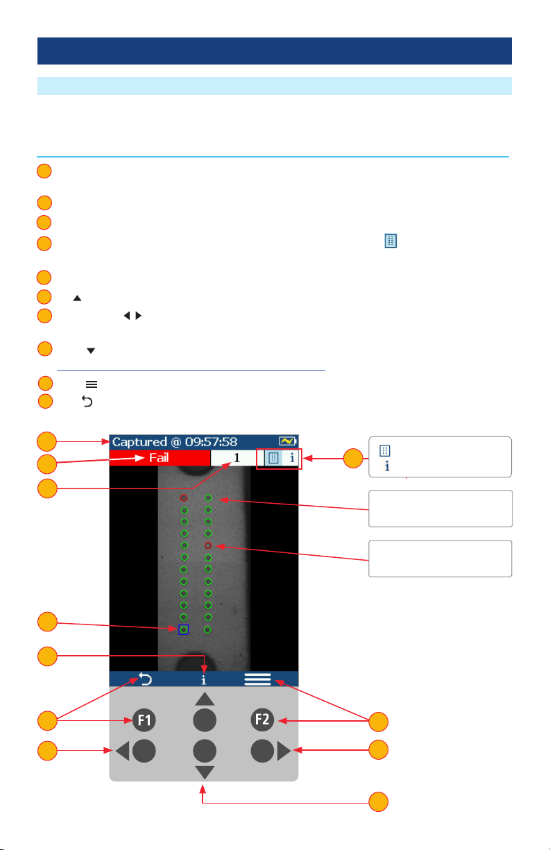
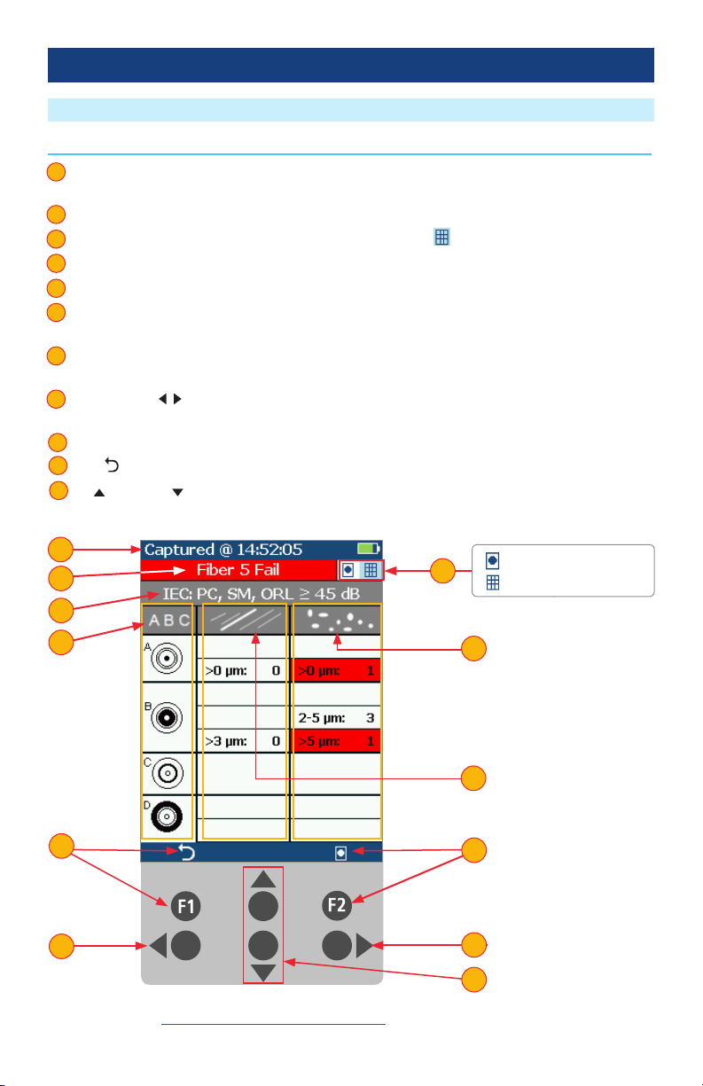
Pass/Fail Analysis Details Page
Getting Started
Note: See section “Setting Pass/Fail Criteria” on page 21 for details on how to select and/or edit
pass/fail analysis rules.
# Description
1 Screen Title: displays File Name (e.g. COO1-003) if saved image is shown or Captured @ hh:mm:ss
if unsaved image is shown.
2 Fiber Analysis status (Pass or Fail): shown only if the Pass/Fail option is enabled in Settings.
3 Image Details/Analysis Details pages indicator: blue highlight ( ) indicates current page.
4 Analysis Rule applied to determine Pass/Fail.
5 Analysis Zones: A - core, B - cladding, C - adhesive, D - contact area.
6 Scratch analysis results for each zone: reports the number of detected scratches exceeding limit for
each region; highlights failed rules in RED.
7 Defect analysis results for each zone: reports the number of detected defects exceeding limit for
each region; highlights failed rules in RED.
8 Left and Right arrow buttons: press to navigate through bers. Direction of navigation through
bers with Left/Right arrows depends on Key Up/Down settings.
9 F2 button: press to toggle display between the Analysis Details and Image Details pages.
10 Back button: press to return to the Live Image mode.
11 Up and Down arrow buttons: inactive on the Analysis Details page.
1
2
3
4
5
6
7
8
9
10
11
1
2
8
10
3
8
- Image Details Page
- Analysis Details Page
11
5
4
7
6
9

17
Image Information Page
# Description
1 Screen title: displays le name as follows:
• <Cable>-<Connector> (e.g. COO1-003) if saved image is shown.
• ‘Captured @ hh:mm:ss’ if unsaved image is shown.
2 Fiber Analysis status (Pass or Fail): shown only if the Pass/Fail option is enabled in Settings.
3 Number of the currently selected ber.
4 MPO Image Overview/Information pages indicator: blue highlight ( ) indicates current view/page.
5 Results ID eld: displays Job/Scope End/Cable/Pair Mode/Pair Type/Connector information.
6 Time & Date eld: shows time & date of the displayed captured image.
7 Rule eld: indicates pass/fail analysis rule applied.
8 Back button: press to return to the previous screen.
9 Menu button: press to display the Save/Send/Existing Folders menu.
10 Up arrow: press to return to the Overview page.
11 Left and Right arrow buttons: press to navigate through bers. Direction of navigation through
bers with Left/Right arrows depends on Key Up/Down settings.
12 Down arrow: press to display detailed view of the currently selected ber. See section.”Detailed
View of the Currently Selected Fiber” on page 15.
1
2
3
4
5
6
7
8
9
10
11
12
Getting Started
Note: See section “Saving Captured Images” on page 26 for details on how to save results.
1
2
11
4
10
- Image Overview Page
- Image Information Page
12
12
5
6
7
3
8 9

18
Main Menu Overview
Settings Menu Overview
Main Menu
The Main Menu is accessed from Live Image mode by pressing the Menu button. Main Menu is used
to select user preferences, perform general settings, manage saved test results, and perform other non-
test functions.
While in the Settings Menu:
• Press Up/Down arrow buttons to navigate and
select (highlight) the desired menu item.
• For Beeper settings:
–Pressing Select button toggles setting
between enable/disable.
–Pressing Right arrow button enables setting.
–Pressing Left arrow button disables setting.
• For all other settings, press Select button or Right
arrow button to display a sub-menu and edit
the selected parameter.
• Press Back button to return to the previous menu
screen.
• Press Capture Button to return to live image
mode.
While in the Main Menu:
• Press Up/Down arrow buttons to navigate and
select (highlight) one of the menu item as follows.
–Settings: Use to congure Auto Focus, Pass/Fail
criteria, Bluetooth, and general settings
–Results Manager: Use to navigate and review
or send saved test results
–Last Image: Use to recall most recently
viewed image
–WiFi: Congure WiFi for remote access (future)
–Device Info: Use to view serial number, software
revision, etc
• Press Select Aor Right arrow button to display a
sub-screen of the selected menu item
• Press Back Bbutton to return to Live Image mode
Main Menu and Settings
AB

19
Main Menu and Settings
To Enable Auto Focus
1 From the Main Menu, select Settings > Capture > Auto Focus
• Use to enable or disable the auto-focus option / as needed.
To Congure Auto-Save and Auto-Send
2 Highlight and Select Auto-Send. Use to disable auto-send, enable on 1st Capture Key, or enable
on 2nd Capture Key.
3 Highlight and Select Auto-Save. Use to disable auto-send, enable on 1st Capture Key, or enable
on 2nd Capture Key.
To Congure ‘Save to’ Destination
4 Highlight and select Save to Folder/File. Use to select and edit the desired folder/le eld.
When Auto-Send/Save is enabled, press Capture from Live Image mode to auto-focus (if enabled),
capture image, analyze pass/fail (if enabled), then send image and pass/fail results to paired device and
save image and pass/fail results to congured Job/Cable folder.
Note: If Auto-Save or Auto-Send on 2nd Capture Key is enabled, you will be prompted to press the
Capture button again to save or send. Press the Back button if you do not wish to save or send image.
1
2
3
4
1 1
Capture Settings
2
4
3

20
IEC Pass/Fail Analysis
Pass/Fail Analysis
Main Menu and Settings
IEC 61300-3-35 denes connector inspection pass/fail criteria.
Pass/Fail criteria depends on:
• Fiber type (SMF or MMF).
• Connector end face regions:
–A region: Core
–B region: Cladding
–C region: Adhesive (between cladding
and ferrule)
–D region: Physical contact area
• Type of end face aw:
–Scratches
–Defects (contamination, particles, chips)
• Size of aw.
IEC 61300-3-35 for multi-ber MPO/MTP connectors only denes the following regions (or zones):
–A region: Core
–B region: Cladding
Core
Failing
Defect
Passing
Defect
Contact
Adhesive
Cladding
Shown below is the display when the IEC rule for single-mode PC connector with return loss ≥ 45 dB is
selected. The table identies the number of scratches or defects of a certain size, which may be allowed
in each of the core, cladding, and contact regions.
Example IEC Rule
Region Scratch Defect
A: Core
>0 µm: 0
No scratches >0 µm
allowed
>0 µm: 0
No defects >0 µm
allowed
B: Cladding
>3 µm: 0
No scratches >3 µm
allowed
2-5 µm: 5
Up to 5 defects 2-5 µm
diameter allowed
>5 µm: 0
No defects >3 µm
allowed
C: Adhesive
Blank
(No limitations on
scratches)
Blank
(No limitations on
scratches)
D: Contact
Blank
No limitations on
scratches
0 ≥ 10 µm
No defects ≥ 10 µm
allowed
Table of contents
Other AFL Test Equipment manuals


