manuals.online logo
Brands
  1. Home
  2. •
  3. Brands
  4. •
  5. Agora Models
  6. •
  7. Motorized Toy Car
  8. •
  9. Agora Models RM 857 Manual

Agora Models RM 857 Manual

STAGE 91: FRAMEWORK AND WINDOWS FOR THE
LOWER DECK
STAGE 92: FRAMEWORK AND WINDOWS FOR THE
LOWER DECK
STAGE 93: FITTING THE DRIVER’S DOOR AND A
LIGHT FOR ONE OF THE BUS BLINDS
STAGE 94: FITTING THE RIGHT WALL FRAMEWORK
STAGE 95: FITTING THE RIGHT WALL FRAMEWORK
STAGE 96: FITTING THE CEILING ASSEMBLY TO
THE UPPER DECK
STAGE 97: FITTING THE FIRST ROOF PANEL AND
RAIN SHIELDS
STAGE 98: ORGANISING THE WIRING AND FITTING
A ROOF PANEL
STAGE 99: ROOF PANEL AND SIDE STRIPS
STAGE 100: FRONT WINDOW TRIM
AND FINISHING STRIPS
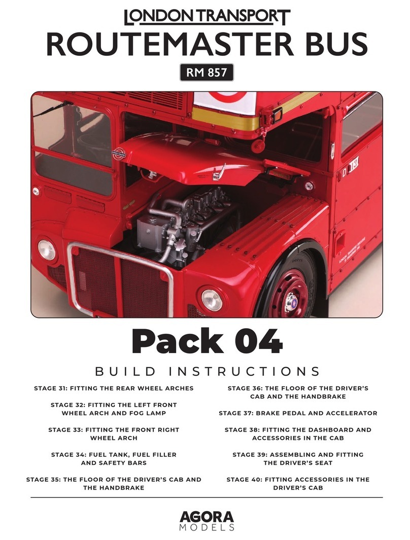
Pack 10
BUILD INSTRUCTIONS
You may find that there is not enough space for the bell pull mechanism to move before the knot
tying the cord to the control slider touches the ceiling framework. Consequently, if the knot is too
large, it will restrict the bell pull mechanism’s function. To resolve this problem, please try re-tying
the cord to a the section of the control slider 55I shown by the red arrow in the image below.
Alternatively, you can also file a notch in the crossbar of ceiling framework 70A in the position
shown by the red arrow in the image below to allow the knot to pass through.
EXPERT ADVICE:EXPERT ADVICE:
BELL PULL MECHANISMBELL PULL MECHANISM
55I
70A
22
AGORAMODELS ROUTEMASTER BUS PB
AGORAMODELS ROUTEMASTER BUS
KEY TO PARTS
91A Left wall framework
91B Handle
91C Window bar
91D Window winder
91E Window frame
91F Sliding window pane
91G Window pane
91H Window pane
BP 1.5 x 3mm (x3)
OP 1.7 x 5mm (x5)
NM 1.5 x 3mm (x3)
EM 1.5 x 4mm (x5)
IMPORTANT!
Store your
model away from
direct sunlight, to
avoid damage to
the windows.
4
STAGE 91
FRAMEWORK AND WINDOWSFRAMEWORK AND WINDOWS
FOR THE LOWER DECKFOR THE LOWER DECK
A section of the lower deck framework is supplied and fitted with
windows and a handle.
NM
91A 91E
91D
91F
91B
91C
91G
91H
EM OPBP
33
AGORAMODELS ROUTEMASTER BUS PB
AGORAMODELS ROUTEMASTER BUS
3
4
1 2
1Fit the window pane 91H to the inside of the left wall
framework 91A. Fix in place with four EM screws.
2Cut away the mouldings that were used in
manufacture from the sliding window pane 91F and
the window frame 91E. Smooth any rough edges.
4Fit the window frame 91E (with
sliding window pane 91F) on to the
outside of the left wall framework 91A. Fit
the window pane 91G to the inside of the
framework, as shown. Fix in place from
the inside of the window pane 91G with
four OP screws.
3Fit the sliding window pane 91F
into the window frame 91E so that
ridges on the ends of part 91F fit into the
grooves in the frame 91E. The ‘metal’
edge goes at the top.
EM
x2
91H
91F
91A
91E
EM
x2
91A
OP
OP
91E
91F
44
AGORAMODELS ROUTEMASTER BUS 5
AGORAMODELS ROUTEMASTER BUS
5 6
6Identify the fixing points for the handle 91B on the frame
91A, adjacent to the sliding window. Note that a peg on
the handle fits into a socket on the frame 91A. Make sure it is
the right way round. Fix in place with two NM screws.
5Fix the upper part of the window frame 91E to the
framework 91A, from the inside, with two BP
screws.
A non-opening window and a
sliding window have been fitted
to the section of the left lower-
deck framework.
91E
NM
x2
91B
91A
91A
BP
x2
5
5
AGORAMODELS ROUTEMASTER BUS
7 8
7Fit the window winder 91D to the bar 91C. This is a
push fit connection.
8Take the upper and lower deck assembly from the
previous stage. Handle with care to prevent the top
deck from slipping. Fit the bar 91C to the front left window
on the lower deck (on part 48A), with the winder inside
the model. This part will be secured at a later stage.
91C
91D
91C
48A
66
AGORAMODELS ROUTEMASTER BUS 7
AGORAMODELS ROUTEMASTER BUS
Finished views
A bar has been
fitted to the
front window of
the lower deck.
The section
of framework
(fitted with
windows in
steps 1–6) will be
fitted in a future
stage and hold
the bar in place.
7
7
AGORAMODELS ROUTEMASTER BUS
KEY TO PARTS
92A Left wall framework
92B Window bar
92C Winder
92D Window frame
92E Sliding window pane
92F Window pane
92G Window pane
BP 1.5 x 3mm (x3)
OP 1.7 x 5mm (x5)
JP 2.3 x 4mm (x12)
EM 1.5 x 4mm (x5)
FM 2.3 x 4mm (x11)
STAGE 92
FRAMEWORK AND WINDOWSFRAMEWORK AND WINDOWS
FOR THE LOWER DECKFOR THE LOWER DECK
Another section of the lower deck framework is supplied and
fitted with windows.
FM
92A 92E
92D
92F
92B
92C
92G
EMJP
OPBP
88
AGORAMODELS ROUTEMASTER BUS PB
AGORAMODELS ROUTEMASTER BUS
3
4
12
1Fit the window pane 92G to the inside of the left wall
framework 92A. Fix in place with four EM screws.
2Cut away the mouldings that were used in
manufacture from the sliding window pane
92E and the window frame 92D. Smooth any
rough edges.
4Fit the window frame
92D (with sliding
window pane 92E) on to the
outside of the left wall
framework 92A. Fit the
window pane 92F to the
inside of the framework, as
shown. Fix in place from the
inside of the window pane
92F with four OP screws.
3Fit the sliding window pane 92E into the
window frame 92D so that ridges on the
ends of part 92E fit into the grooves in the
frame 92D. The ‘metal’ edge of the sliding
window goes at the top.
EM
x2
92G
92E
92A
92D
92D
92F
EM
x2
92A
OP
OP
92D
92E
99
AGORAMODELS ROUTEMASTER BUS 10
AGORAMODELS ROUTEMASTER BUS
55Fix the upper part of the window frame
92D to the framework 92A, from the
inside, with two BP screws.
66Turn the window frame
92A over and take the
left wall 91A from the
previous stage. Align the two
parts so that the three tabs on
part 92A fit over
corresponding screw sockets
in part 91A. Fix together with
three FM screws. The image
below shows the parts fitted
together.
92D
92A
BP
x2
92A
FM
x2
FM
91A
10
10
AGORAMODELS ROUTEMASTER BUS
7
9
8
7Fit the window winder 92C to the bar 92B.
This is a push fit connection.
9Position the framework
assembly from step 6
against the side of the lower
deck, enclosing the
window bars. The tabs
along the top fit into
notches, as indicated
by the light blue dotted
lines. Fix in place along the
top to parts 48A and 49A
with four JP screws as shown.
Use six JP screws to fit the middle
part of the framework to the wall
panels 48A and 49A (inset below left)
Fix the lower edge of the framework to
chassis frames 17A and 16A with six FM
screws (Inset below).
8Take the upper and lower deck assembly from the
previous stage. Handle with care. Fit the bar 92B to
the left window on the lower deck (on part 49A), as
shown, with the winder inside the model.
92B
49A
92A
91A
JP
x2
JP
x2
92C
48A
92B
49A
49A 92A 92A
16A
17A
91A
91A
FM
x2
FM
x2
FM
x2
48A
JP
x2
JP
x2
JP
x2
11 11
AGORAMODELS ROUTEMASTER BUS 12
AGORAMODELS ROUTEMASTER BUS
Finished views
12
12
AGORAMODELS ROUTEMASTER BUS
KEY TO PARTS
93A Outer door panel
93B Window pane
93C Handle (x2)
93D Inner door panel
93E Bar
DP 1.7 x 4mm (x5, black)
NM 1.5 x 3mm (x4, red)
KM 1.5 x 5mm (x10, red)
EM 1.5 x 4mm (x5, silver)
FM 2.3 x 4mm (x5, black)
Before
starting to fit
the light panel,
test that the light
is working. Re-test
once it has been
fitted.
4
STAGE 93
FITTING THE DRIVER’S DOOR AND AFITTING THE DRIVER’S DOOR AND A
LIGHT FOR ONE OF THE BUS BLINDSLIGHT FOR ONE OF THE BUS BLINDS
The driver’s door is assembled and fitted. We also insert an LED
lighting panel near the position of the blind over the open platform.
93E
93D
93C
93B
93A
FM
DP NM
EM
KM
13 13
AGORAMODELS ROUTEMASTER BUS PB
AGORAMODELS ROUTEMASTER BUS
3
1
2
1Identify the smaller blind light panel
71E and bring it around to the rear
left corner of the upper deck.
2Carefully lift the upper deck slightly, so
that you can slip the light panel 71E in
between the outer wall framework 86A and
the ceiling framework 70A. Ensure that the
backing paper is facing away from you.
3Bring the cable up behind the
framework 86A (circled). Bring the
LED panel 71E through the opening so
that it hangs down in front of the
framework 86A. It is advisable to
temporarily secure the panel in place with
a piece of low-tack tape.
86A
86A
71E
71E
78C
70A
70A
71E
14 14
AGORAMODELS ROUTEMASTER BUS 15
AGORAMODELS ROUTEMASTER BUS
44Take the outer door panel of the driver’s door
93A and position it on your work surface as
shown. Take the window pane 93B and position it
on the door panel 93A as indicated. Note the
orientation of the ridge on part 93B (see inset).
5 6
78
6Turn the assembly over and fit the bar 93E across the
outer door panel 93A. Fix in place with three NM (red)
screws. Ensure the screws are fully inserted so they do not catch
on the door frame when the sliding door has been fitted.
7Identify the fixing points for the first handle 93C
on the outer door panel 93A. Fix in place with
two EM screws.
8Turn the door over and position the second
handle 93C on the inner door panel 93D, as
shown. Fix in place by the window with two EM screws.
5Fit the inner door panel 93D over
the outer door panel 93A so that the screw holes
at the corners are aligned and the window 93B is
enclosed. Fix in place with four DP screws.
NM
x3
EM
x2
DP
x2
DP
x2
93C
93A
93A
93E
93B
93B
93D
93A
93A
EM
x2
93C
93D
15
15
AGORAMODELS ROUTEMASTER BUS
9
11
10
12
9Carefully lift the upper deck away from the lower deck so that you can fit
the driver’s door in place. As you fit the door, ensure that the pegs on the
bottom of the inner door panel 93D fit into the slot in the cabin floor 35A
(inset above). Lower the upper deck in place, ensuring that the pegs on the top
of the inner door panel 93D fit into the groove in the cab ceiling 76A.
11Fix the front framework 80F to the right wall
framework 87A, the left wall framework 85A and
the cab frame 40A using three FM screws.
10Check that the door is properly fitted and
able to slide open and closed. Fix the right
wall framework 87A to the cab frame 40A with
an FM screw.
12Take the front (blind) frame 80H (supplied with
stage 80) and fit it against the front frame 80F.
Check that the screw holes are aligned, and fix in place with
eight KM (red) screws.
FM
FM
x3
93D
93D
35A
87A
40A
76A
93D
35A
76A
85A
40A
80F
87A
80H
80F
KM
x4
KM
x4
16 16
AGORAMODELS ROUTEMASTER BUS 17
AGORAMODELS ROUTEMASTER BUS
Finished views
13
13Turn the model around so that you can access
the stair rail. Fit the ends of the handrails 84I
and 57B together.
The driver’s door has been
fitted and an LED has been
inserted over the open
platform. An outer frame
section has been fitted
around the front blind.
57B
84I
17
17
AGORAMODELS ROUTEMASTER BUS
KEY TO PARTS
94A Right wall framework
94B Step
94C Handle
94D Window bar
94E Winder
94F Window frame
94G Sliding window pane
94H Window pane
94I Window pane
BP 1.5 x 3mm (x3)
OP 1.7 x 5mm (x5)
JP 2.3 x 4mm (x6)
NM 1.5 x 3mm (x4)
EM 1.5 x 4mm (x5)
GM 2.3 x 5mm (x6)
STAGE 94
FITTING THE RIGHT WALLFITTING THE RIGHT WALL
FRAMEWORKFRAMEWORK
Windows and a handle are fitted to the right wall framework, which
is then attached to the model.
94E 94H
94F
94I
94D
94C 94G
94B
94A
GM
OP JP NM EM
BP
18 18
AGORAMODELS ROUTEMASTER BUS PB
AGORAMODELS ROUTEMASTER BUS
4
1
23
1Take the right wall framework
94A and the window pane 94I.
Fix the window pane to the inside of
the framework using four EM
screws..
2As in previous stages, remove the excess moulding
from the manufacturing process on the sliding
window pane 94G and the window frame 94F.
3Fit the sliding window pane 94G into the window
frame 94F so that ridges on the ends of part 94G
fit into the grooves in the frame 94F. The ‘metal’ edge
goes at the top.
4Fit the window frame 94F (with
sliding window pane 94G) on to
the outside of the right wall framework
94A. Fix in place from the inside with
two BP screws.
94G
BP
BP
94G
94F
94F
94F
94A
94A 94I
EM
x4
19 19
AGORAMODELS ROUTEMASTER BUS 20
AGORAMODELS ROUTEMASTER BUS
5
5Fit the window pane 94H on the inside of
the right wall framework 94A , beneath the
sliding window. Fix in place with four OP screws.
6
7
8
7Fit the window winder 94E into the hole in the window bar 94D.
Position the bar on the outside of the lower deck of the assembled
model (48B), across the window behind the driver’s seat. (inset).
8Position the right wall
framework 94A against the
right side wall of the lower deck
48B so that the window bar is
enclosed. Fix the lower edge of part
94A to the edge of the chassis
frame 17A using three GM screws.
6Identify the fixing point for the handle 94C on
the side of the right wall framework 94A, next to
the sliding window. Make sure you have the correct
orientation. Fix in place with two NM screws.
When
you are fitting
large frames with
numerous screws, it
may help to only partially
fit the screws at first and
then fully tighten once
they are all in place.
4
GM
x3
NM
x2
OP
x4
94A
48B
17A
94D
94D
48B
94E
94A
94H
94C
94A
20
20
AGORAMODELS ROUTEMASTER BUS

Other Agora Models Motorized Toy Car manuals
Agora Models MERCEDES-BENZ W196R Manual

Agora Models

Agora Models MERCEDES-BENZ W196R Manual

Agora Models Corvette Sting Ray Z06 N03 1963 Pack 03 Manual

Agora Models

Agora Models Corvette Sting Ray Z06 N03 1963 Pack 03 Manual

Agora Models Jaguar E-Type Pack 10 Manual

Agora Models

Agora Models Jaguar E-Type Pack 10 Manual

Agora Models 1965 SHELBY COBRA 427 S/C Manual

Agora Models

Agora Models 1965 SHELBY COBRA 427 S/C Manual

Agora Models JAGUAR E-TYPE Manual

Agora Models

Agora Models JAGUAR E-TYPE Manual

Agora Models JAGUAR E-TYPE Pack 01 Manual

Agora Models

Agora Models JAGUAR E-TYPE Pack 01 Manual

Agora Models STEVE MCQUEEN'S ICONIC PORSCHE 917KH Pack 02 Manual

Agora Models

Agora Models STEVE MCQUEEN'S ICONIC PORSCHE 917KH Pack 02 Manual

Agora Models FDNY FIRE TRUCK TOWER LADDER 9 Manual
Agora Models

Agora Models FDNY FIRE TRUCK TOWER LADDER 9 Manual

Agora Models Pack 07 Manual

Agora Models

Agora Models Pack 07 Manual

Agora Models LAMBORGHINI MIURA Pack 01 Manual

Agora Models

Agora Models LAMBORGHINI MIURA Pack 01 Manual

Agora Models STEVE MCQUEEN'S ICONIC PORSCHE 917KH Manual

Agora Models

Agora Models STEVE MCQUEEN'S ICONIC PORSCHE 917KH Manual

Agora Models STEVE MCQUEEN'S ICONIC PORSCHE 917KH Pack 05 Manual

Agora Models

Agora Models STEVE MCQUEEN'S ICONIC PORSCHE 917KH Pack 05 Manual

Agora Models STEVE MCQUEEN'S ICONIC PORSCHE 917 KH Pack... Manual

Agora Models

Agora Models STEVE MCQUEEN'S ICONIC PORSCHE 917 KH Pack... Manual

Agora Models Shelby GT500 1967 Super Snake Manual

Agora Models

Agora Models Shelby GT500 1967 Super Snake Manual

Agora Models SHELBY COBRA 427 SEMI-COMPETITION 1965 Manual

Agora Models

Agora Models SHELBY COBRA 427 SEMI-COMPETITION 1965 Manual

Agora Models MERSEDES-BENZ 300SL GULLWING 1955 Pack 03 Manual

Agora Models

Agora Models MERSEDES-BENZ 300SL GULLWING 1955 Pack 03 Manual

Agora Models FDNY FIRE TRUCK TOWER LADDER 9 Manual

Agora Models

Agora Models FDNY FIRE TRUCK TOWER LADDER 9 Manual

Agora Models SHELBY COBRA 1965 Manual

Agora Models

Agora Models SHELBY COBRA 1965 Manual

Agora Models Mercedes 300SL Gullwing 1955 Manual

Agora Models

Agora Models Mercedes 300SL Gullwing 1955 Manual

Agora Models SHELBY COBRA 427 SEMI-COMPETITION 1965 Manual

Agora Models

Agora Models SHELBY COBRA 427 SEMI-COMPETITION 1965 Manual

Agora Models FDNY Fire Truck Manual

Agora Models

Agora Models FDNY Fire Truck Manual

Agora Models Lamborghini MIURA Pack 11 Manual
Agora Models

Agora Models Lamborghini MIURA Pack 11 Manual

Agora Models STEVE MCQUEEN'S ICONIC PORSCHE 917KH Pack 10 Manual
Agora Models

Agora Models STEVE MCQUEEN'S ICONIC PORSCHE 917KH Pack 10 Manual

Agora Models JAGUAR E-TYPE Manual

Agora Models

Agora Models JAGUAR E-TYPE Manual

Popular Motorized Toy Car manuals by other brands

MN Model MN-86KS Products Installation Instructions

MN Model

MN Model MN-86KS Products Installation Instructions

Jamara Strabenwalze 2,4 GHz Instruction

Jamara

Jamara Strabenwalze 2,4 GHz Instruction

Opitec 101.141 instructions

Opitec

Opitec 101.141 instructions

Jamara Strong Bull 460825 Instruction

Jamara

Jamara Strong Bull 460825 Instruction

Tamiya FAST ATTACK VEHIClE manual

Tamiya

Tamiya FAST ATTACK VEHIClE manual

Dorel PACIFIC CYCLE KT1246 owner's manual

Dorel

Dorel PACIFIC CYCLE KT1246 owner's manual

Agora Shelby GT500 Super Snake Build instructions

Agora

Agora Shelby GT500 Super Snake Build instructions

Team Losi LST 3XL-E RTR instruction manual

Team Losi

Team Losi LST 3XL-E RTR instruction manual

RAID Tamco Instruction manual & parts catalogue

RAID

RAID Tamco Instruction manual & parts catalogue

Team Assocciated Nitro TC3 manual

Team Assocciated

Team Assocciated Nitro TC3 manual

Serpent X20FWD manual

Serpent

Serpent X20FWD manual

HOMCOM LAMBORGHINI AVENTADOR SVJ owner's manual

HOMCOM

HOMCOM LAMBORGHINI AVENTADOR SVJ owner's manual

NORDIC PLAY BMW S1000 RR manual

NORDIC PLAY

NORDIC PLAY BMW S1000 RR manual

Jamara 410011 instruction manual

Jamara

Jamara 410011 instruction manual

REVELL 80 DODGE RAMCHARGER Assembly manual

REVELL

REVELL 80 DODGE RAMCHARGER Assembly manual

Traxxas Slash 4x4 Ultimate 6807L owner's manual

Traxxas

Traxxas Slash 4x4 Ultimate 6807L owner's manual

Force1 VELOCITY X RC user manual

Force1

Force1 VELOCITY X RC user manual

Eduard M-ATV MRAP exterior manual

Eduard

Eduard M-ATV MRAP exterior manual

manuals.online logo
manuals.online logoBrands
  • About & Mission
  • Contact us
  • Privacy Policy
  • Terms and Conditions

Copyright 2025 Manuals.Online. All Rights Reserved.