AKM AKD4432-SA User manual

[AKD4432-SA]
[KM119002] 2017/03
GENERAL DESCRIPTION
The AKD4432-SA is an evaluation board for the AK4432 (32-bit 2ch DAC) that supports DVD-Audios,
Car-Audio Systems, allowing quick evaluation with digital audio interface.
Ordering guide
AKD4432-SA --- Evaluation board for AK4432
(Control software is packed with this board)
FUNCTION
3 type digital audio interface
- Optical input
- COAX input
- External input
2ch Analog outputs
USB Port for Serial control
COAX In
AK4432
DIR
Opt In
AK4118A
5x2pin
Header
(DSP)
R
PIC
18F4550
USB
B-TYPE
I2C/SPI
MCLK
BICK
LRCK
SDTI
Audio
Signals
+12V
AGND
Reg
12V→3.3V
Reg
12V→3.3V
DGND
DGND
D3.3V
D3.3V
VSS
LVDD
AVDD
DGND
L
Figure 1. AKD4432-SA Block Diagram
AK4432 Sound Quality Evaluation Board Rev.2
AKD4432-SA
- 1-
Downloaded from Arrow.com.

[AKD4432-SA]
[KM119002] 2017/03
Description
(1) Connector for Power supply
+12V、AGND
Terminals for power supply. Refer to table1.
(2) AOUTL、AOUTR
RCA Jack for analog outputs.
(3) COAX、OPT
Input SPDIF signal to AK4118A.
When using the COAX:R302=0Ω、R303=Open (Default)
When using the OPT:R302=Open、R303=0Ω
(4) AK4118A
AK4118A outputs digital data to AK4432 as DIR.
(5) PORT303
External digital data inputs to AK4432.
MCLK、BICK、LRCK、SDTI
When using the PORT303:R310=R311=R312=R313= 51Ω
R314= R315= R316=R317=Open
When using the AK4118A:R310=R311=R312=R313=Open (Default)
R314= R315= R316=R317=51Ω(Default)
(6) USB
USB Port. It is possible to set up the registers of AK4432 from PC via the USB port.
(7) PIC18F4550
USB control IC
(8) SW301
Setting switch for AK4118A.Upside is “Hi”, downside is “Lo”.
Refer to Table2.SW301 setting.
(9) SW401
Setting switch for AK4432.Upside is “Hi”, downside is “Lo”
Refer to Table5.SW401 setting.
(10) SW402
Power down switch for AK4432.Upside is “Hi (on)”, downside is “Lo (off)”
(11) SW403
Mute switch for AK4432.
Push :AK4432 is mute
Release:AK4432 is unmute
(12)SW404
Power down switch for AK4118A.Upside is “Hi (on)”, downside is “Lo (off)”
- 3-
Downloaded from Arrow.com.Downloaded from Arrow.com.Downloaded from Arrow.com.

[AKD4432-SA]
[KM119002] 2017/03
Evaluation Board Manual
■Operation sequence
[1] Set up power supplies
The power should be separated from the source of a power supplier.
Name of
connector
Color of
connector
Voltage
Use application
Comment and attention
+12V
Red
+12V
・Regulator
Should always be
connected.
GND
Black
0V
・Ground
Should always be
connected.
Table 1. Power supply line setting
[2] Switch setting
It should be set to match the mode.
(1) SW301 setting
No.
Switch Name
Function
default
1
DIF2
DIF2-pin of AK4118A
Hi
2
DIF1
DIF1-pin of AK4118A
Lo
3
DIF0
DIF0-pin of AK4118A
Lo
4
OCKS1
OCKS1-pin of AK4118A
Hi
5
OCKS0
OCKS0-pin of AK4118A
Lo
Table 2. SW301 setting
Mode
DIF2 pin
DIF1 pin
DIF0 pin
DAUX
SDTO
LRCK
BICK
I/O
I/O
0
0
0
0
24bit, Left
justified
16bit, Right
justified
H/L
O
64fs
O
1
0
0
1
24bit, Left
justified
18bit, Right
justified
H/L
O
64fs
O
2
0
1
0
24bit, Left
justified
20bit, Right
justified
H/L
O
64fs
O
3
0
1
1
24bit, Left
justified
24bit, Right
justified
H/L
O
64fs
O
4
1
0
0
24bit, Left
justified
24bit, Left
justified
H/L
O
64fs
O
default
5
1
0
1
24bit, I2S
24bit, I2S
L/H
O
64fs
O
6
1
1
0
24bit, Left
justified
24bit, Left
justified
H/L
I
64-128fs
I
7
1
1
1
24bit, I2S
24bit, I2S
L/H
I
64-128fs
I
Table 3. AK4118A Audio interface format
OCKS1 pin
OCKS0 pin
(X’tal)
MCKO1
MCKO2
fs (max)
0
0
256fs
256fs
256fs
96 kHz
0
1
256fs
256fs
128fs
96 kHz
1
0
512fs
512fs
256fs
48 kHz
default
1
1
128fs
128fs
64fs
192 kHz
Table 4. AK4118A MCLK setting
- 4-
Downloaded from Arrow.com.Downloaded from Arrow.com.Downloaded from Arrow.com.Downloaded from Arrow.com.

[AKD4432-SA]
[KM119002] 2017/03
(2) SW401 setting
No.
Switch Name
Function
default
1
I2C
I2C pin of AK4432
H:I2C mode
L:SPI mode
Hi
2
PS
PS pin of AK4432
H:Parallel mode
L:Serial mode
Hi
3
I2CFIL
I2CFIL pin of AK4432
H:Fast Mode Plus(1MHz)
L:Fast Mode(400kHz)
Lo
4
ACKS
ACKS pin of AK4432
H:Auto Setting Mode
L:Manual Setting Mode
Hi
5
DIF
DIF pin of AK4432(Parallel mode only)
H:32bit I2S compatible
L:32bit LSB justified
Lo
6
Open
-
-
Table 5. SW401 setting
(3) SW402/SW403/SW404 setting
SW402
AK4432-PDN
Power down switch for AK4432
Hi:Power up
Lo:Power down
※Should be “Hi”during operation AK4432.
SW403
MUTE
Mute switch for AK4432(Parallel mode only)
Release:Unmute
Push:Mute
SW404
AK4118-PDN
Power down switch for AK4118A
Hi:Power up
Lo:Power down
※Should be “Hi”during operation AK4118A.
Table6. SW402/SW403/SW404 setting
[3] USB connect (Serial mode only)
Connect the board to PC with the USB cable.
[4] Power on
Turn on the power to the board. In case of serial mode, startup AK4432 control software.
[5] Setup the control registers (Serial mode only)
Refer to “Control soft manual”.
- 5-
Downloaded from Arrow.com.Downloaded from Arrow.com.Downloaded from Arrow.com.Downloaded from Arrow.com.Downloaded from Arrow.com.

[AKD4432-SA]
[KM119002] 2017/03
Control Soft Manual
■Evaluation Board and Control Soft Settings
1.Set an evaluation board properly.
2.Connect a USB control box (AKUSBIF-B) and an evaluation board.
Pay attention about direction of the 10pin header when connecting to an AKUSBIF-B.
3.Connect a PC (IBM-AT compatible) and the USB control box (AKUSBIF-B).
The USB control box is recognized as HID (Human Interface Device) on the PC.
It is not necessary to install a new driver.
4.Start up the control program.
When the screen does not display “AKUSBIF-B”at bottom left, reconnect the PC and the USB control box, and push
the [Port Reset] button.
5. Proceed evaluation by following the process below.
[Support OS]
Windows XP / Vista / 7
Figure 3. Control Software Window
- 6-
Downloaded from Arrow.com.Downloaded from Arrow.com.Downloaded from Arrow.com.Downloaded from Arrow.com.Downloaded from Arrow.com.Downloaded from Arrow.com.

[AKD4432-SA]
[KM119002] 2017/03
■Operation Overview
Function, register map and testing tool can be controlled by this control soft. These controls are selected by upper tabs.
Buttons which are frequently used such as register initializing button “Write Default”, are located outside of the switching
tab window. Refer to the “■ Dialog Boxes” for details of each dialog box setting.
1. [Port Reset]: For when connecting to PC
Click this button after the control soft starts up when connecting to PC.
2. [Write Default]: Initializes Registers
When the device is reset by a hardware reset, use this button to initialize the registers.
3. [All Write]: Executes write commands for all registers displayed.
4. [All Read]: Executes read commands for all registers displayed.
5. [Save]: Saves current register settings to a file.
6. [Load]: Executes data write from a saved file.
7. [All Req Write]: Opens “All Req Write”dialog box.
8. [Data R/W]: Opens “Data R/W”dialog box
9. [Sequence]: Opens “Sequence”dialog box.
10. [Sequence (File)]: Opens “Sequence(File)”dialog box.
11. [Read]: Reads current register settings and displays on to the register area (on the right of the main window).
This is different from [All Read] button, it does not reflect to a register map, only displaying register
settings in hexadecimal.
- 7-
Downloaded from Arrow.com.Downloaded from Arrow.com.Downloaded from Arrow.com.Downloaded from Arrow.com.Downloaded from Arrow.com.Downloaded from Arrow.com.Downloaded from Arrow.com.

[AKD4432-SA]
[KM119002] 2017/03
Function Tab
1. [Function]: Function Map
This tab is for a function and volume setting.
Each operation is executed by [Function] buttons on the left side of the screen.
Figure 4. Window of [ Function ]
[Function] Tab
•Audio I/F Setting: Audio interface function setting.
•DAC Setting Control: DAC function setting.
• Digital Volume Control: Digital volume function setting.
1-1.[Audio I/F Setting]
1. [Auto Setting]: ACKS mode select.
No check: ACKS is invalid, Manual Setting Mode (default)
Checked: ACKS is valid, Auto Setting Mode
2. [Sampling Speed Mode(DFS1-0 bits)]: Sampling speed mode setting.(when ACKS invalid)
Normal Speed Mode
32kHz~48kHz
Double Speed Mode
64kHz~96kHz
Quad Speed Mode
128kHz~192kHz
3. [TDM Mode Select(TDM1-0 bits)]: TDM fomat select.
Normal mode (default)
TDM128 mode (Quad Speed Mode)
TDM256 mode (Double Speed Mode)
- 8-
Downloaded from Arrow.com.Downloaded from Arrow.com.Downloaded from Arrow.com.Downloaded from Arrow.com.Downloaded from Arrow.com.Downloaded from Arrow.com.Downloaded from Arrow.com.Downloaded from Arrow.com.

[AKD4432-SA]
[KM119002] 2017/03
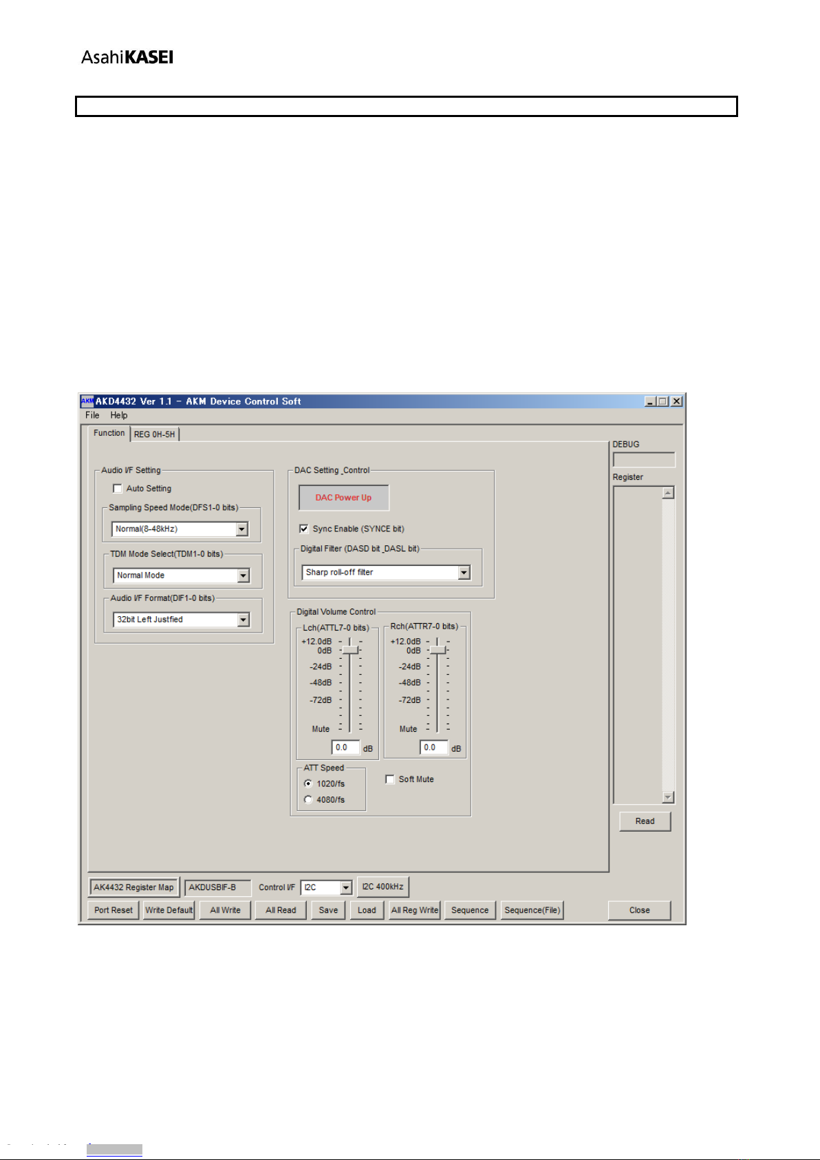
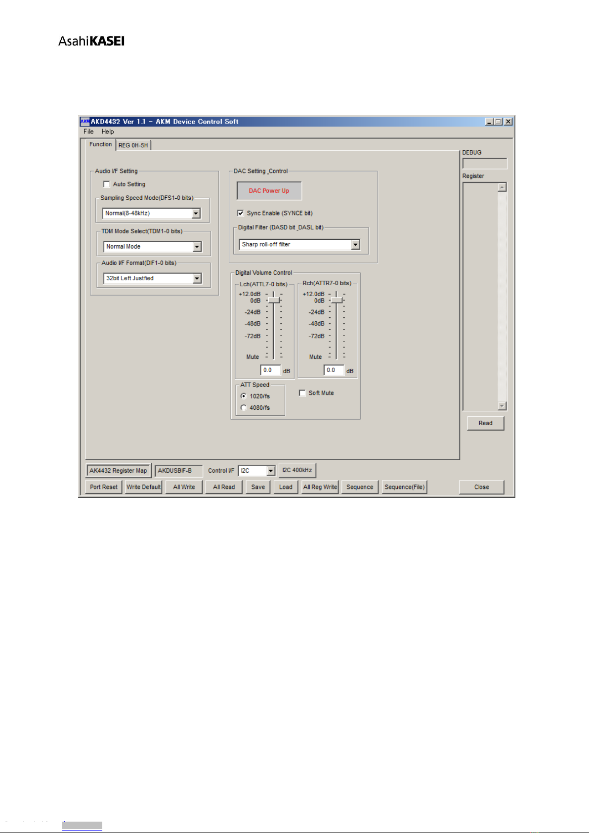
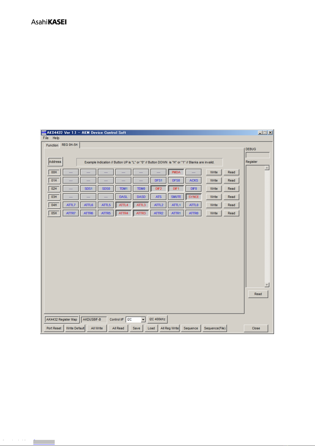
4. [Audio I/F Format(DIF1-0 bits)]: Audio interface format select.
16bit, Right justified
20bit, Right justified
24bit, Left justified
24bit, I2S
24bit, Right justified
32bit, Right justified
32bit, Left justified (default)
32bit, I2S
1-2.[DAC Setting Control]
1. [DAC Power Up/Down]: DAC power management function setting by push down of a button.
DAC Power Up: RMDA invalid, normal operation(default)
DAC Power Down: RMDA valid, power down
2. [Sync Enable(SYNCE bit)]: Clock sync function select by the check patterns.
No checked: Clock sync invalid
Check: Clock sync valid (default)
3. [Digital Filter(DASD bit_DASL bit)]: Digital filter function setting.
Sharp roll-off filter (default)
Slow roll-off filter
Short delay Sharp roll-off filter
Short delay Slow roll-off filter
1-3.[Digital Volume Control]
1. [Lch(ATTL7-0 bits)]: Volume setting of Lch by the slide button.
+12.0dB,
0dB (default)
~-115dB,
Mute
2. [Rch(ATTR7-0 bits)]: Volume setting of Rch by the slide button.
+12.0dB,
0dB (default)
~-115dB,
Mute
3. [ATT Speed]: Digital volume transfer time setting.
1020/fs (default)
4080/fs
4. [Soft Mute]: Soft mute function setting by the check patterns.
No checked : Mute off , Normal (default)
Checked : Mute on
- 9-
Downloaded from Arrow.com.Downloaded from Arrow.com.Downloaded from Arrow.com.Downloaded from Arrow.com.Downloaded from Arrow.com.Downloaded from Arrow.com.Downloaded from Arrow.com.Downloaded from Arrow.com.Downloaded from Arrow.com.

[AKD4432-SA]
[KM119002] 2017/03
Tab Functions
2. [REG]: Register Map
This tab is for a register writing and reading.
Each bit on the register map is a push-button switch.
Button Down indicates “H” or “1” and the bit name is in red (when read only it is in deep red).
Button Up indicates “L” or “0” and the bit name is in blue (when read only it is in gray)
Grayout registers are Read Only registers. They can not be controlled.
The registers which is not defined in the datasheet are indicated as “---”.
Figure 5. Window of [ REG ]
- 10-
Downloaded from Arrow.com.Downloaded from Arrow.com.Downloaded from Arrow.com.Downloaded from Arrow.com.Downloaded from Arrow.com.Downloaded from Arrow.com.Downloaded from Arrow.com.Downloaded from Arrow.com.Downloaded from Arrow.com.Downloaded from Arrow.com.

[AKD4432-SA]
[KM119002] 2017/03
1-1. [Write]: Data Writing Dialog
It is for when changing two or more bits on the same address at the same time.
Click [Write] button located on the right of the each corresponded address for a pop-up dialog box.
When the checkbox is checked, the data wil be “H” or “1”. When the checkbox is not checked, the data will be “L”
or “0”. Click [OK] to write setting values to the registers, or click [Cancel] to cancel this setting.
Figure 6. Window of [ Register Set ]
1-2. [Read]: Data Read (I2C mode only)
Click [Read] button located on the right of the each corresponded address to execute a register read.
After register reading, the display will be updated regarding to the register status.
Button Down indicates “H” or “1” and the bit name is in red (when read only it is in deep red).
Button Up indicates “L” or “0” and the bit name is in blue (when read only it is in gray)
Please be aware that button statuses will be changed by a Read command.
- 11-
Downloaded from Arrow.com.Downloaded from Arrow.com.Downloaded from Arrow.com.Downloaded from Arrow.com.Downloaded from Arrow.com.Downloaded from Arrow.com.Downloaded from Arrow.com.Downloaded from Arrow.com.Downloaded from Arrow.com.Downloaded from Arrow.com.Downloaded from Arrow.com.

[AKD4432-SA]
[KM119002] 2017/03
■Dialog Boxes
1. [All Reg Write]: All Reg Write dialog box
Click [All Reg Write] button in the main window to open register setting files.
Register setting files saved by [Save] button can be applied.
Figure 7. Window of [ All Reg Write ]
[Open (left)]: Selects a register setting file (*.akr).
[Write]: Executes register writing by the setting of selected file.
[Write All]: Executes all register writings.
Selected files are executed in descending order.
[Help]: Opens a help window.
[Save]: Saves a register setting file assignment. The file name is “*.mar”.
[Open (right)]: Opens a saved register setting file assignment “*. mar”.
[Close]: Closes the dialog box and finish the process.
[All Write]: A chosen register setting file is written in together.
Execution order of the choice file will be the order of the bottom from the window top.
[Start]: Register writing in of all files is carried out from the upper side.
[Stop]: Register writing in is canceled.
[Interval time]: The waiting time until writing in of the next register setting file is begun is designated.
(5msec ~10,000msec)
[Current No] : The file number which is being written in is indicated.
- 12-
Downloaded from Arrow.com.Downloaded from Arrow.com.Downloaded from Arrow.com.Downloaded from Arrow.com.Downloaded from Arrow.com.Downloaded from Arrow.com.Downloaded from Arrow.com.Downloaded from Arrow.com.Downloaded from Arrow.com.Downloaded from Arrow.com.Downloaded from Arrow.com.Downloaded from Arrow.com.

[AKD4432-SA]
[KM119002] 2017/03
~ Operating Suggestions ~
1. Those files saved by [Save] button and opened by [Open] button on the right of the dialog “*.mar”should
be stored in the same folder.
2. When register settings are changed by [Save] button in the main window, re-read the file to reflect new
register settings.
- 13-
Downloaded from Arrow.com.Downloaded from Arrow.com.Downloaded from Arrow.com.Downloaded from Arrow.com.Downloaded from Arrow.com.Downloaded from Arrow.com.Downloaded from Arrow.com.Downloaded from Arrow.com.Downloaded from Arrow.com.Downloaded from Arrow.com.Downloaded from Arrow.com.Downloaded from Arrow.com.Downloaded from Arrow.com.

[AKD4432-SA]
[KM119002] 2017/03
2. [Sequence]: Sequence Dialog Box
Click [Sequence] button to open register sequence setting dialog box.
Register sequence can be set in this dialog box.
Figure 8. Window of [Sequence ]
~ Sequence Setting ~
Set register sequence by following process bellow.
1. Select a command
Use [Select] pull-down box to choose commands.
Corresponding boxes will be valid.
< Select Pull-down menu >
· No_use: Not using this address
· Register: Register writing
· Reg(Mask): Register writing (Masked)
· Interval: Taking an interval
· Stop: Pausing the sequence
· End: Finishing the sequence
- 14-
Downloaded from Arrow.com.Downloaded from Arrow.com.Downloaded from Arrow.com.Downloaded from Arrow.com.Downloaded from Arrow.com.Downloaded from Arrow.com.Downloaded from Arrow.com.Downloaded from Arrow.com.Downloaded from Arrow.com.Downloaded from Arrow.com.Downloaded from Arrow.com.Downloaded from Arrow.com.Downloaded from Arrow.com.Downloaded from Arrow.com.

[AKD4432-SA]
[KM119002] 2017/03
2. Input sequence
[Address]: Data address
[Data]: Writing data
[Mask]: Mask
[Data] box data is ANDed with [Mask] box data. This is the actual writing data.
When Mask = 0x00, current setting is hold.
When Mask = 0xFF, the 8bit data which is set in the [Data] box is written.
When Mask =0x0F, lower 4bit data which is set in the [Data] box is written.
Upper 4bit is hold to current setting.
[ Interval ]: Interval time
Valid boxes for each process command are shown bellow.
· No_use : None
· Register : [Address], [Data], [Interval]
· Reg(Mask) : [Address], [Data], [Mask], [Interval]
· Interval : [Interval]
· Stop : None
· End : None
~ Control Buttons~
The function of Control Button is shown bellow.
[DEL]:Step with a check is deleted.
[INS]: Insert the one step that was last deleted step with a check.
[Start Step]: Select Start Step.
No.1 Step: Start from No.1 step.
Checked Step: Start from step with a check.
[Start]: Executes the sequence
[Help]: Opens a help window
[Save]: Saves sequence settings as a file. The file name is “*.aks”.
[Open]: Opens a sequence setting file “*.aks”.
[Close]: Closes the dialog box and finishes the process.
~ Stop of the sequence~
When “Stop” is selected in the sequence, the process is paused and it starts again when [Start] button is clicked
Restarting step number is shown in the “Start Step” box. When finishing the process at the end of sequence,
“Start Step” will return to “1”.
The sequence can be started from any step by writing the step number to the “Start Step”box.
Write “1” to the “Start Step” box and click [Start] button, when restarting the process from the beginning.
- 15-
Downloaded from Arrow.com.Downloaded from Arrow.com.Downloaded from Arrow.com.Downloaded from Arrow.com.Downloaded from Arrow.com.Downloaded from Arrow.com.Downloaded from Arrow.com.Downloaded from Arrow.com.Downloaded from Arrow.com.Downloaded from Arrow.com.Downloaded from Arrow.com.Downloaded from Arrow.com.Downloaded from Arrow.com.Downloaded from Arrow.com.Downloaded from Arrow.com.

[AKD4432-SA]
[KM119002] 2017/03
4. [Sequence(File)]: Sequence Setting File Dialog Box
Click [Sequence(File)] button to open sequence setting file dialog box.
Those files saved in the “Sequence setting dialog” can be applied in this dialog.
Figure 9. Window of [ Sequence(File) ]
[Open (left)]: Opens a sequence setting file (*.aks).
[Start]: Executes the sequence by the setting of selected file.
[Start All]: Executing all sequence settings.
Selected files are executed in descending order.
[Help]: Opens a help window.
[Save]: Saves a sequence setting file assignment. The file name is “*.mas”.
[Open(right)]: Opens a saved sequence setting file assignment “*. mas”.
[Close]: Closes the dialog box and finishes the process.
~ Operating Suggestions ~
1. Those files saved by [Save] button and opened by [Open] button on the right of the dialog “*.mas” should be
stored in the same folder.
2. When “Stop” is selected in the sequence the process will be paused and a pop-up message will appear. Click
“OK” to continue the process.
Figure 10. Window of [ Sequence Pause ]
- 16-
Downloaded from Arrow.com.Downloaded from Arrow.com.Downloaded from Arrow.com.Downloaded from Arrow.com.Downloaded from Arrow.com.Downloaded from Arrow.com.Downloaded from Arrow.com.Downloaded from Arrow.com.Downloaded from Arrow.com.Downloaded from Arrow.com.Downloaded from Arrow.com.Downloaded from Arrow.com.Downloaded from Arrow.com.Downloaded from Arrow.com.Downloaded from Arrow.com.Downloaded from Arrow.com.

[AKD4432-SA]
[KM119002] 2017/03
Measurement Results
[Measurement condition]
・Measurement unit : Audio Precision, SYS-2722 (No.00103)
・MCKI : 512fs ,256fs,128fs
・BICK : 64fs
・fs : 48kHz、96kHz
・Bit : 24bit
・Input Frequency : 1kHz
・Power Supply :+12V, GND
AVDD=LVDD=3.3V (Regulator)
・Pass : COAX→AK4118A(DIR) →AK4432 →AOUT
・Temperature : Room
・Board Setting : Parallel Mode
[Measurement Results]
1. fs=48kHz, MCLK=512fs, BICK=64fs
Result
Unit
Lch
Rch
DAC : SDTI => DAC => L/ROUT
S/(N+D)
fs = 48kHz (0dBFS, 20kHz LPF)
90.0
89.8
dB
DR
fs = 48kHz (-60dBFS, A-Weighted)
108.0
108.0
dB
S/N
fs = 48kHz (No Inputs, A-Weighted)
108.0
108.0
dB
2. fs=96kHz, MCLK=256fs, BICK=64fs
Result
Unit
Lch
Rch
DAC : SDTI => DAC => L/ROUT
S/(N+D)
fs = 96kHz (0dBFS, 40kHz LPF)
89.7
89.6
dB
DR
fs = 96kHz (-60dBFS, 40kHz LPF)
102.8
102.8
dB
S/N
fs = 96kHz (No Input, 40kHz LPF)
102.8
102.8
dB
3. fs=192kHz, MCLK=128fs, BICK=64fs
Result
Unit
Lch
Rch
DAC : SDTI => DAC => L/ROUT
S/(N+D)
fs = 192kHz (0dBFS, 40kHz LPF)
89.6
89.6
dB
DR
fs = 192kHz (-60dBFS, 40kHz LPF)
102.8
102.8
dB
S/N
fs = 192kHz (No Inputs, 40kHz LPF)
102.8
102.8
dB
- 17-
Downloaded from Arrow.com.Downloaded from Arrow.com.Downloaded from Arrow.com.Downloaded from Arrow.com.Downloaded from Arrow.com.Downloaded from Arrow.com.Downloaded from Arrow.com.Downloaded from Arrow.com.Downloaded from Arrow.com.Downloaded from Arrow.com.Downloaded from Arrow.com.Downloaded from Arrow.com.Downloaded from Arrow.com.Downloaded from Arrow.com.Downloaded from Arrow.com.Downloaded from Arrow.com.Downloaded from Arrow.com.

[AKD4432-SA]
[KM119002] 2017/03
[Plot Data]
1. fs=48kHz, MCLK=512fs, BICK=64fs
DAC : SDTI => DAC => AOUTL/AOUTR
Figure 11. FFT (0dBFS) [fs = 48kHz]
Figure 12. FFT (-60dBFS) [fs = 48kHz]
-180
+0
-160
-140
-120
-100
-80
-60
-40
-20
d
B
r
A
20 20k50 100 200 500 1k 2k 5k 10k
Hz
-180
+0
-160
-140
-120
-100
-80
-60
-40
-20
d
B
r
A
20 20k50 100 200 500 1k 2k 5k 10k
Hz
- 18-
Downloaded from Arrow.com.Downloaded from Arrow.com.Downloaded from Arrow.com.Downloaded from Arrow.com.Downloaded from Arrow.com.Downloaded from Arrow.com.Downloaded from Arrow.com.Downloaded from Arrow.com.Downloaded from Arrow.com.Downloaded from Arrow.com.Downloaded from Arrow.com.Downloaded from Arrow.com.Downloaded from Arrow.com.Downloaded from Arrow.com.Downloaded from Arrow.com.Downloaded from Arrow.com.Downloaded from Arrow.com.Downloaded from Arrow.com.

[AKD4432-SA]
[KM119002] 2017/03
Figure 13. FFT (No Inputs fs=48kHz]
Figure 14. THD+N vs. Amplitude (Input Level) [fs = 48kHz]
-180
+0
-160
-140
-120
-100
-80
-60
-40
-20
d
B
r
A
20 20k50 100 200 500 1k 2k 5k 10k
Hz
-140
-70
-130
-120
-110
-100
-90
-80
d
B
r
A
-140 +0-120 -100 -80 -60 -40 -20
dBFS
- 19-
Downloaded from Arrow.com.Downloaded from Arrow.com.Downloaded from Arrow.com.Downloaded from Arrow.com.Downloaded from Arrow.com.Downloaded from Arrow.com.Downloaded from Arrow.com.Downloaded from Arrow.com.Downloaded from Arrow.com.Downloaded from Arrow.com.Downloaded from Arrow.com.Downloaded from Arrow.com.Downloaded from Arrow.com.Downloaded from Arrow.com.Downloaded from Arrow.com.Downloaded from Arrow.com.Downloaded from Arrow.com.Downloaded from Arrow.com.Downloaded from Arrow.com.

[AKD4432-SA]
[KM119002] 2017/03
Figure 15. THD+N vs. Input Frequency [fs = 48kHz, 0dBFS Inputs]
Figure 16. Linearity [fs = 48kHz]
-130
-60
-120
-110
-100
-90
-80
-70
d
B
r
A
20 20k50 100 200 500 1k 2k 5k 10k
Hz
-140
+0
-120
-100
-80
-60
-40
-20
d
B
r
A
-140 +0-120 -100 -80 -60 -40 -20
dBFS
- 20-
Downloaded from Arrow.com.Downloaded from Arrow.com.Downloaded from Arrow.com.Downloaded from Arrow.com.Downloaded from Arrow.com.Downloaded from Arrow.com.Downloaded from Arrow.com.Downloaded from Arrow.com.Downloaded from Arrow.com.Downloaded from Arrow.com.Downloaded from Arrow.com.Downloaded from Arrow.com.Downloaded from Arrow.com.Downloaded from Arrow.com.Downloaded from Arrow.com.Downloaded from Arrow.com.Downloaded from Arrow.com.Downloaded from Arrow.com.Downloaded from Arrow.com.Downloaded from Arrow.com.
Table of contents
Other AKM Motherboard manuals