[AKD4629-A]
<KM101901> 2011/01
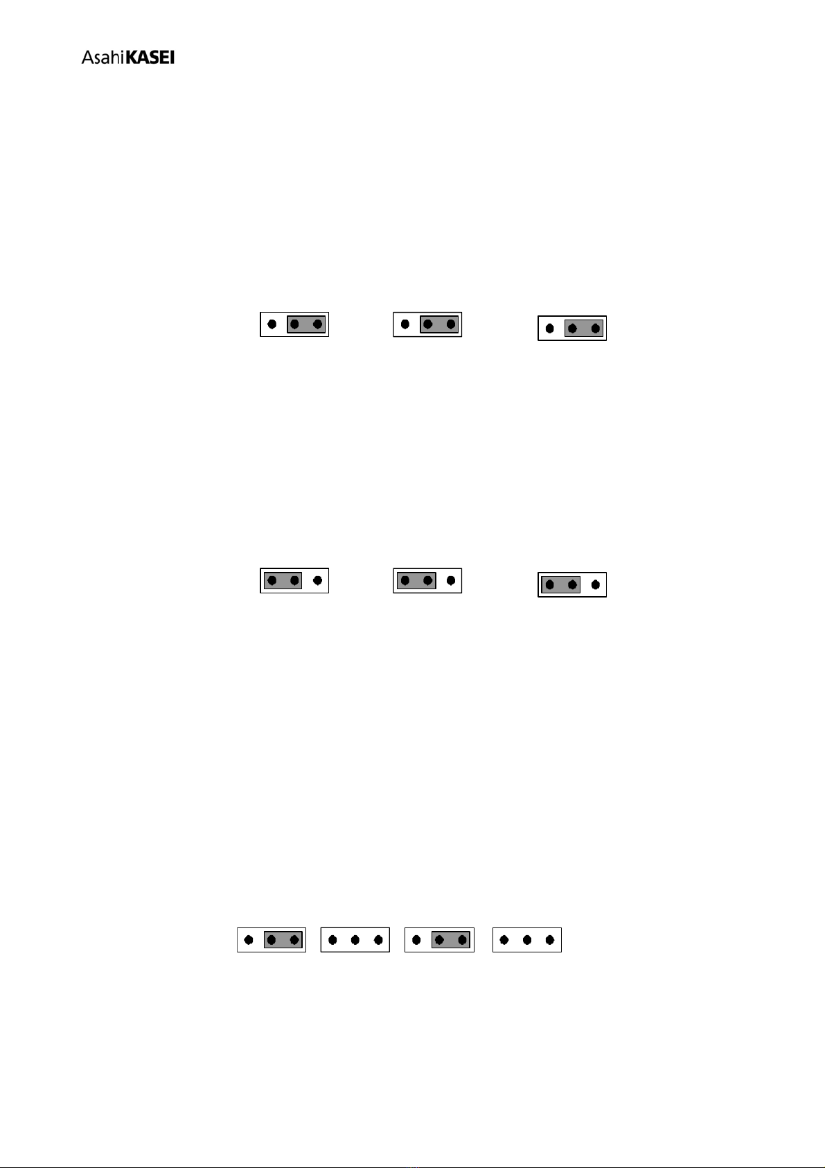
DIP Switch set up
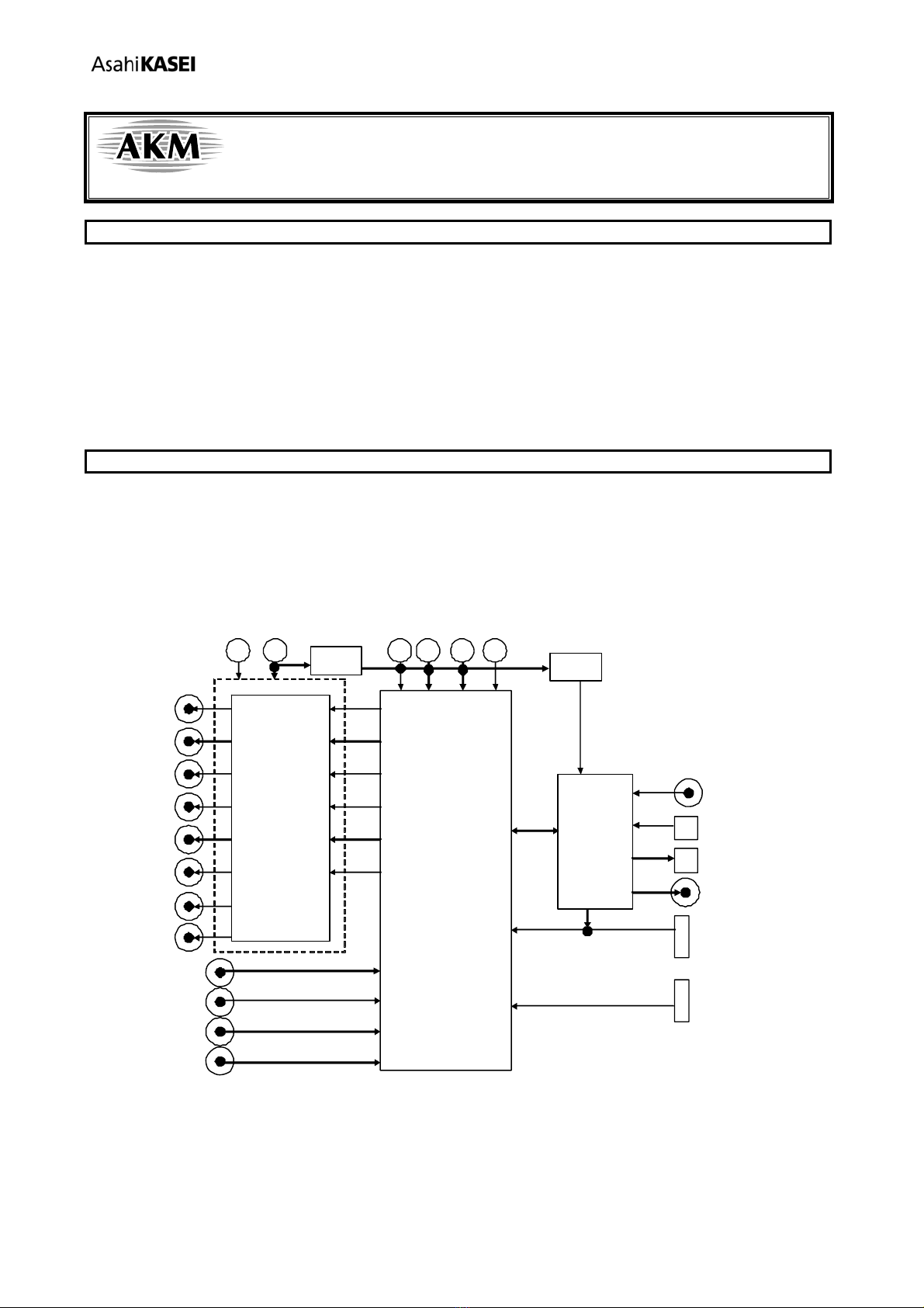
[SW2] (MODE1): Mode settings for AK4629.
About the TDM mode of AK4629, please refer to Page 18 of AK4629’s datasheet.
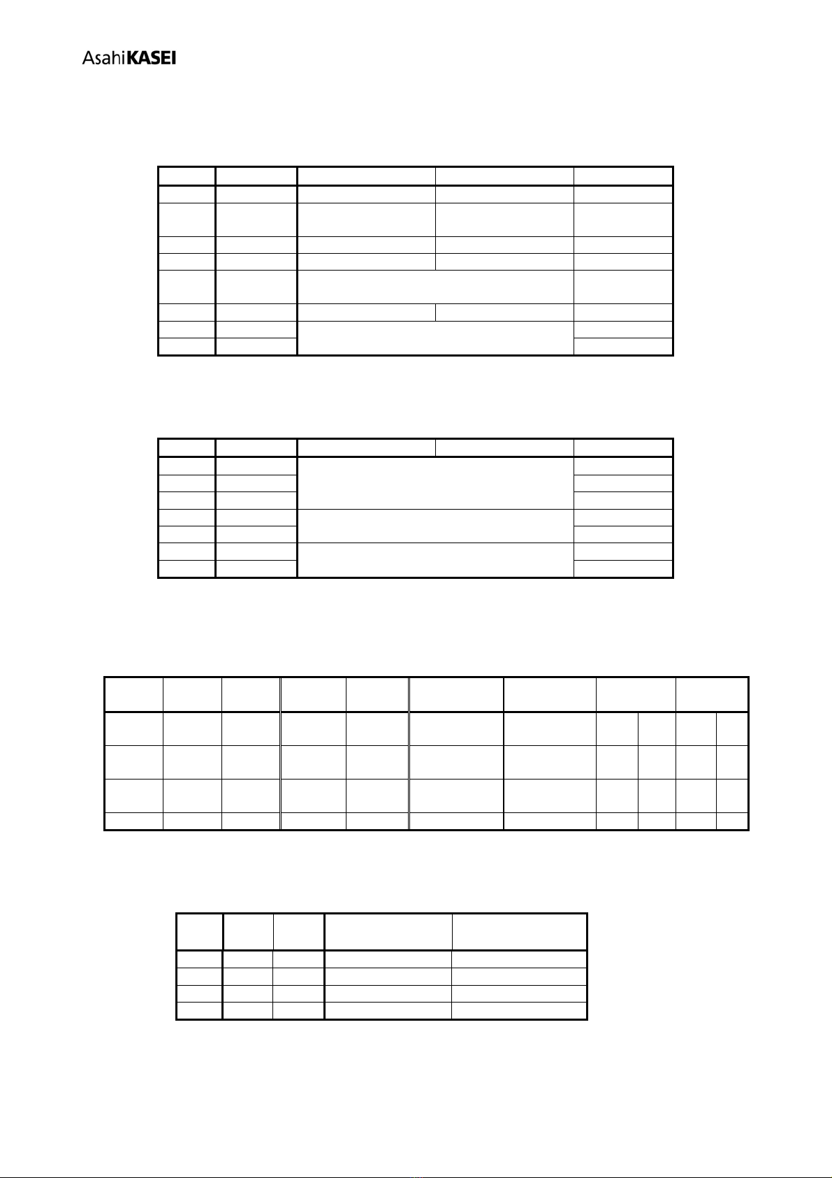
No. Name “H” “L” Default
1 TDM0 TDM Mode Normal Mode L
2 SGL
ADC Single-ended
Input Mode
ADC Differential
Input Mode L
3 I2C I2C Bus 3-wire Serial L
4 DFS0 Double Speed Normal Speed L
5 DZFE Zero Input Detect.
Refer to the datasheet P23 of the AK4629. L
6 PS Parallel Control mode Serial Control mode H
7 CAD1 Chip Address Select. Refer to Table 9 L
8 CAD0 L
Table 3 Mode Setting for AK4629
[SW3] (AK4118 Mode_setting): Mode setting for AK4118.
No. Name “H” “L” Default
1 DIF2
AK4118’s Audio Data Format Settings, and
AK4629’s Audio Data Format Settings when
Parallel Control Mode. See Table 5 and Table 6
H
2 DIF1 L
3 DIF0 L
4 OCKS1 AK4118’s Master Clock Settings.
See Table 7
H
5 OCKS0 L
6 CM1
AK4118’s Clock Operation Mode Select.
See Table 8
L
7 CM0 L
Table 4 Mode Setting for AK4118
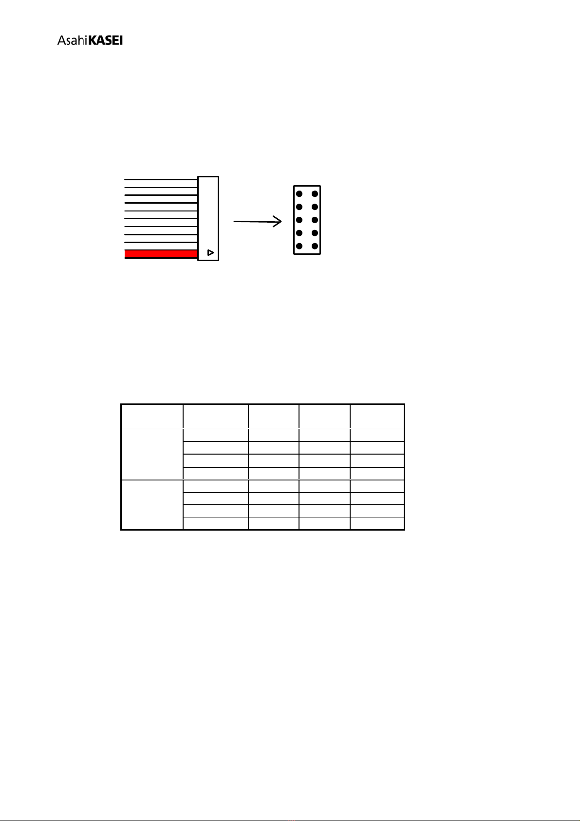
AK4118’s audio data format and AK4629’s audio data format are set up at the same time by settings of SW3-1
(DIF2), SW3-2 (DIF1) and SW3-3 (DIF0) when AK4629 is on Parallel Control Mode.
SW3-1
DIF2
SW3-2
DIF1
SW3-3
DIF0
AK4629
DIF1
AK4629
DIF0
AK4118
DAUX
AK4118
SDTO
LRCK BICK
0 1 0 0 0 24bit, Left
justified
20bit, Right
justified
H/L O 64fs O
0 1 1 0 1 24bit, Left
justified
24bit, Right
justified
H/L O 64fs O
1 0 0 1 0 24bit, Left
justified
24bit, Left
justified
H/L O 64fs O (Default)
1 0 1 1 1 24bit, I2S 24bit, I2S L/H O 64fs O
Table 5 AK4114’s Audio Data Format (Parallel control mode <Default>)
Both of settings of DIF1-0 bits of AK4629’s registers and settings of SW3-1 (DIF2), SW3-2 (DIF1), SW3-3
(DIF0) are necessary when AK4629 is on Serial Control Mode.
Mode DIF1
bit
DIF0
bit SDTO1-2 SDTI1-3
0 0 0 24bit, Left justified 20bit, Right justified
1 0 1 24bit, Left justified 24bit, Right justified
2 1 0 24bit, Left justified 24bit, Left justified (Default)
3 1 1 24bit, I2S 24bit, I2S
Table 6 AK4629’s Audio data formats (Serial control mode)