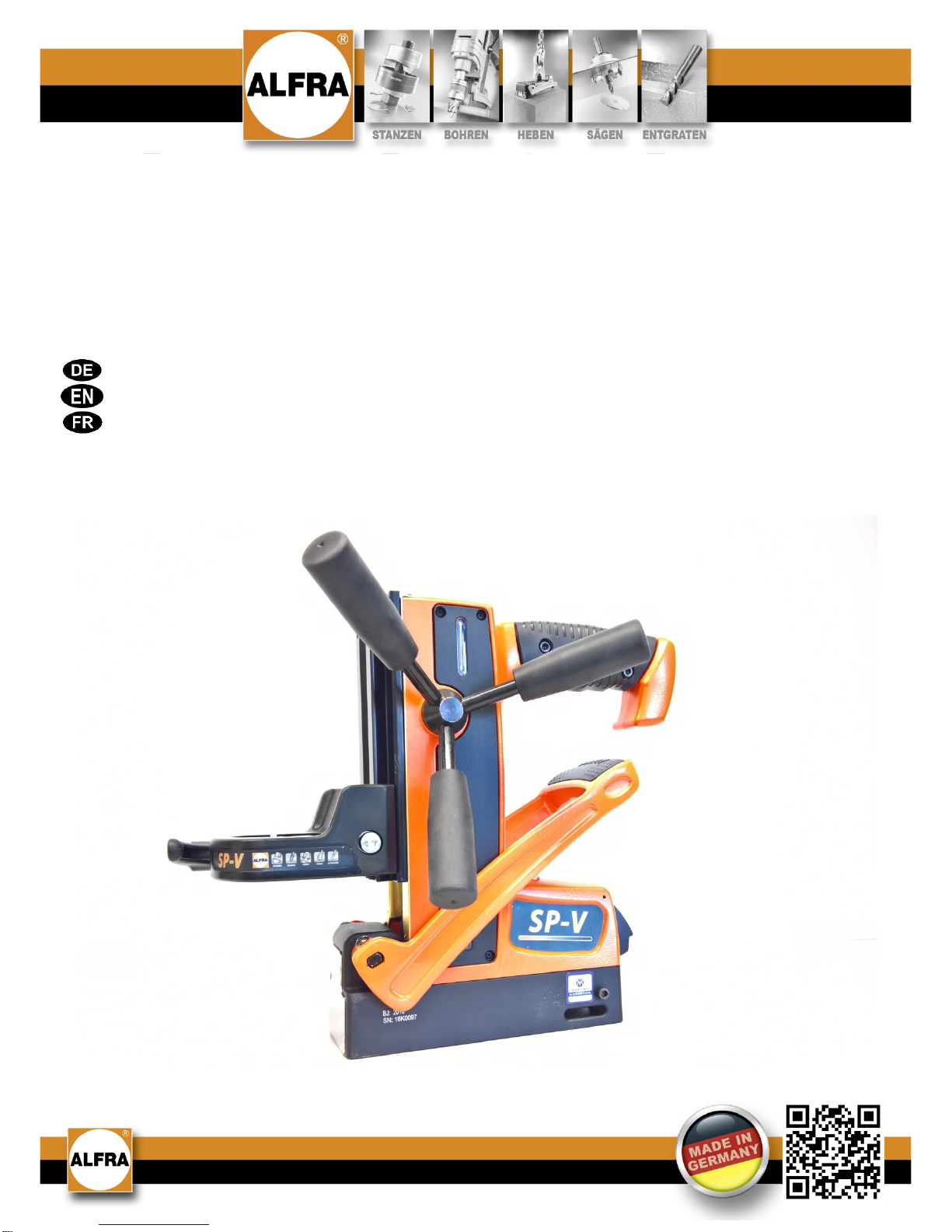
ALFRA ROTABEST SP-V User manual

Bedienungsanleitung / Operation manual /
Mode d‘emploi
ALFRA ROTABEST SP-V
Universal-Magnetbohrständer mit Eurobund-Aufnahme
Universal Magnetic Drill Stand with Euro Collar Clamp
Support de perceuse à socle magnétique universel avec mandrin Euro collet
Art.-Nr. 18343 / Prod.-No.18343 / N° art.18343

2
Inhaltsverzeichnis
Sicherheitshinweise, Bestimmungsgemäße Verwendung 3
Technische Daten, Verfügbares Zubehör 4
Gerätebeschreibung 5
Inbetriebnahme 6
Besonderheiten im Umgang mit schaltbaren Permanentmagneten 7
Wartung und Inspektion 8
EG-Konformitätserklärung 9
Vor Inbetriebnahme Bedienungsanleitung lesen und aufbewahren!
Contents
Safety Instructions, Proper Use 10
Technical Data, Available Accessories 11
Description 12
Start-up 13
Special Information on Handling Switchable Permanent Magnets 14
Maintenance and Inspection 15
CE Declaration of Conformity 16
Before use read and save these instructions!
Table des matières
Consignes de sécurité, Utilisation conforme à l’usage prévu 17
Données techniques, Accessoires disponibles 18
Description de l’appareil 19
Mise en service 20
Particularités lors de la manipulation des aimants permanents commutables 21
Maintenance et contrôle 22
Déclaration CE de conformité 23
À lire avant la mise en service puis à conserver!

3
Sehr geehrter Kunde,
vielen Dank, dass Sie sich für ein ALFRA-Produkt entschieden haben. Lesen Sie diese Bedienungsanleitung vor
der ersten Verwendung Ihres neuen Gerätes aufmerksam durch und heben Sie sie auf, um bei Bedarf darin
nachschlagen zu können.
Sicherheitshinweise
Beim Arbeiten mit dieser Maschine entstehen durch unsachgemäße Handhabung und/oder schlechte Wartung
beträchtliche Gefahren, die zur Zerstörung der Maschine und zu schweren Unfällen mit erheblichen körperlichen
Schäden und führen können. Beachten Sie daher alle folgenden Sicherheitshinweise und wenden Sie sich bei
Fragen an unser Service-Team.
Immer…
den schaltbaren Permanentmagneten vollständig aktivieren
den Magneten auf metallischen, ferromagnetischen Materialien aktivieren
die gesamte Magnetfläche beim Arbeiten nutzen
auf planen Oberflächen arbeiten
die Magnetfläche reinigen und von Schmutz, Spänen sowie Schweißkörnern befreien
den Magnetbohrständer sanft absetzen, um eine Beschädigung der Magnethaftfläche zu
vermeiden
beim Bohren an Wänden oder Decken mit dem Sicherheitsgurt sichern
den Anweisungen der Bedienungsanleitung folgen
neue Nutzer in den sicheren Gebrauch der Maschine einweisen
mit Schutzbrille und Ohrenschutz arbeiten
Schutzschild verwenden, sofern im Lieferumfang enthalten
die lokalen, landesspezifischen Richtlinien befolgen
trocken lagern
Niemals…
bohren, ohne vorher den Magneten aktiviert zu haben
auf runden oder gewölbten Objekten arbeiten
auf mehreren Werkstücken übereinander bohren
die Maschine verändern oder Hinweisschilder entfernen
die Maschine bei Beschädigung oder bei fehlenden Teilen verwenden
die Magnetunterseite mit starken Stößen oder Schlägen belasten oder beschädigen
ohne fachgerechte Einweisung benutzen
benutzen, sofern diese Bedienungsanleitung nicht vollständig gelesen und verstanden wurde
den Magnetbohrständer zum Unterstützen, Heben oder Transportieren von Personen oder
Lasten nutzen
bei Temperaturen über 50°C (122°F) lagern oder betreiben
die Maschine unbeaufsichtigt hängen lassen
mit ätzenden Stoffen in Verbindung bringen
Personen mit einem Herzschrittmacher oder anderen medizinischen Apparaten dürfen den
Magnetbohrständer nur nach vorheriger Zustimmung eines Arztes benutzen!
Niemals in rotierende Teile fassen! Bei laufendem Motor Hände und Finger vom Arbeitsbereich
fernhalten, es besteht Verletzungsgefahr!

4
Bestimmungsgemäße Verwendung
Dieser Magnetbohrständer mit einer Eurobund-Aufnahme (Ø 43 mm) und einem schaltbarem
ALFRA TML-Permanentmagneten, ist zur Aufnahme von kabelgebundenen, netzbetriebenen Bohrmaschinen
bestimmt. In Kombination mit einer Bohrmaschine ist der Magnetständer zum Bohren mit Kern- oder Vollbohrern
auf ferromagnetischen Werkstücken bestimmt. Er darf ausschließlich in trockener und wettergeschützter
Umgebung verwendet werden. Die Maschine kann waagerecht, senkrecht oder über Kopf eingesetzt werden.
Technische Daten
Art.-Nr. und Bezeichnung:
18343 SP-V
Werkzeugaufnahme:
Ø 43 mm Eurobund
Ø 1,69“ Eurobund
Bohr Ø max. in Stahl
- Kernbohrer:
- Spiralbohrer:
12 - 35 mm
bis Ø13 mm DIN 338
½“ – 1 38
⁄“
½“
Hub:
105 mm + 80 mm Höhenverstellung
an Schlitten
4 18
⁄
“
+ 318
⁄“Höhenverstellung
an Schlitten
Magnetfußgröße:
72 x 190 mm
2 ¾“ x 7 ½“
Magnethaftkraft:
7500 N
1686 lbs
Tool-Force:
(auf 10 mm Stahl)
2800 N
630 lbs @ 3/8” Stahl
Tool-Force:
(auf 6 mm Stahl)
2300 N
520 lbs @ 2/8” Stahl
Min. Materialstärke:
3 mm
1/8“
Gewicht:
7 kg
15 lbs
Verfügbares Zubehör
Art.-Nr.
Transportkasten
02120.K
Kühlmittel ALFRA BIO 4000
21040
Kühlmitteleinrichtung
189412029
Schutzschild
189414052
Bohrfutter mit Weldonschaft bis 13 mm
18107
Sicherheitsgurt
189490501
Inbusschlüssel 2,5 mm
DIN911-2,5
Inbusschlüssel 4,0 mm
DIN911-4
Inbusschlüssel 6,0 mm
DIN911-6
Spänehaken
189480022

5
Gerätebeschreibung
Der Magnetbohrständer kann durch den eingebauten mechanisch schaltbaren TML-Permanentmagneten (D) an
ferromagnetischen Werkstücken befestigt werden. Hierfür muss der Hebel des Magneten (G) herunter gedrückt
werden und die Sicherheitslasche (F) korrekt einrasten. Eine sich selbst justierende Schwalbenschwanzführung
(C), an der der Spannhals (A) befestigt ist, kann über das Drehkreuz (H) in der Höhe verstellt werden. An diesem
Spannhals (Ø 43 mm) können kabelgebundene, netzbetriebene Bohrmaschinen fest arretiert werden.
Als zusätzliche Drehmomentabstützung ist der Spannhals mit einer Nase versehen, damit die Bohrmaschine dort
einrasten kann. Auf der Rückseite des Bohrständers befinden sich das Typenschild und eine Befestigungs-
möglichkeit für die beigelegten Inbusschlüssel.
A) Ø43 mm Aufnahme
G) Hebel für Magneten
B) Schnellspannhebel
H) Drehkreuz
C) Schlitten und Stellschrauben
zum Justieren auf der Rückseite
D) Magnetfuß
E) Aussparung für Sicherheitsgurt
F) Sicherheitslasche

6
Inbetriebnahme
Sie erhalten einen vollständig montierten Magnetbohrständer sowie eine detaillierte Bedienungsanleitung. Bitte
prüfen Sie bei Erhalt der Ware deren Zustand auf mögliche Transportschäden und den Lieferumfang auf
Vollständigkeit. Wenden Sie sich bei Problemen bitte umgehend an den Hersteller.
Vor dem ersten Gebrauch unbedingt die Bedienungsanleitung lesen!
1. Zuerst Schnellspannhebel öffnen und die Bohrmaschine möglichst vollständig in die Aufnahme einsetzen.
Die rot markierte Nase sollte als zusätzliche Drehmomentabstützung genutzt werden, um ein ungewolltes
Verdrehen der Bohrmaschine zu vermeiden.
2. Den Schnellspannhebel fest schließen.
3. Der Hebel des schaltbaren Permanentmagneten befindet sich in einer nach oben gerichteten Stellung. Der
Magnet ist deaktiviert, sodass Sie die Maschine positionieren können. Eine leichte magnetische Vorspannung
erleichtert das Ausrichten der Maschine an senkrechten Wänden oder in Zwangslagen. Bei Arbeiten an
Wänden und Decken die Bohreinheit mit dem Sicherheitsgurt sichern.
4. Drücken Sie den Hebel bis zum Anschlag nach unten. Achten Sie darauf, dass die Sicherheitslasche
deutlich hörbar einrastet. Der Magnet ist nun aktiviert.
Vor dem Bohren sicherstellen, dass sich der Hebel des Magneten in der Position befindet.
5. Nach der Aktivierung des Permanentmagneten die Netzleitung der Bohrmaschine einstecken und den Motor
einschalten.
6. Durch Drehen des Drehkreuzes den Motor und den sich drehenden Bohrer langsam zum Werkstück führen.
Während des Bohrvorgangs auf ausreichend Kühlung achten.
7. Nach beendetem Bohrvorgang bewegen Sie den Motor durch Drehen des Drehkreuzes nach oben.
Schalten Sie den Motor der Bohrmaschine aus und ziehen Sie den Netzstecker aus der Steckdose.
8. Nach vollständigem Motorstillstand entfernen Sie die Späne und die restlichen Bohrabfälle.
9. Drücken Sie zum Deaktivieren des Permanentmagneten die schwarze Sicherheitslasche mit dem Handballen
nach innen und ziehen Sie den Hebel nach oben. Reinigen Sie abschließend die Magnetunterfläche von
Spänen oder sonstigen haftenden Rückständen.
Späne mit einem Spänehaken entfernen. Nicht mit bloßer Hand anfassen. Verletzungsgefahr!

7
Besonderheiten im Umgang mit schaltbaren Permanentmagneten
Auf der Unterseite des Magnetbohrständers befindet sich die Haftfläche des eingebauten TML-Permanent-
magneten, welche die Haltekraft im aktivierten Zustand über den Magnetfluss erzeugt. Der Magnet lässt sich durch
Herunterdrücken des Hebels unabhängig von der Netzspannung aktivieren. Zum Lösen die schwarze
Sicherheitslasche mit dem Handballen hineindrücken und den Hebel nach oben ziehen. Die Maschine bleibt auch
bei Stromausfall am Werkstück haften.
Materialstärke
Der Magnetfluss des TML-Permanentmagneten benötigt eine Mindestmaterialstärke von 8 mm, um das Werkstück
vollständig zu durchfluten. Ist diese Materialstärke nicht gegeben, reduziert sich die maximale Haftkraft in
Abhängigkeit von der Materialstärke. Herkömmliche Elektro- oder Permanentmagnete haben ein sehr tief
reichendes Magnetfeld, ähnlich der Pfahlwurzel eines Baumes, und benötigen für das Erreichen der maximalen
Haftkraft eine hohe Materialstärke von mehr als 25 mm. Das kompakte Magnetfeld der TML-Magneten aus dem
Hause ALFRA ähnelt einer Flachwurzel und erreicht die maximale Haftkraft schon bei geringen Materialstärken,
sodass auch auf dünnen Blechen ab 3-4 mm mit ausreichender Haftkraft gebohrt werden kann.
Werkstoff
Die Tragfähigkeit des Permanentmagneten wird auf einem S235 Material ermittelt. Stähle mit einem hohen
Kohlenstoffanteil oder einer durch Wärmebehandlung geänderten Struktur haben eine geringere Haftkraft. Auch
geschäumte oder porenbehaftete Gussbauteile haben eine geminderte Haftkraft.
Material
Magnetkraft in %
Unlegierter Stahl (0,1-0,3% C - Gehalt)
100
Unlegierter Stahl (0,3-0,5% C - Gehalt)
90-95
Stahlguss
90
Grauguss
45
Nickel
11
Edelstahl, Aluminium, Messing
0
Oberflächenbeschaffenheit
Entsteht ein Luftspalt zwischen dem Magneten und dem Werkstück, verringert dies die Haftkraft. So bilden z.B.
auch Farbe, Rost, Zunder, Oberflächenbeschichtungen, Fett oder ähnliche Stoffe einen Abstand, also einen
Luftspalt, zwischen Werkstück und dem schaltbaren Magneten und verringern die Haftkraft.
Temperatur
Die in dem TML-Magneten verbauten Hochleistungspermanentmagnete verlieren ab einer Temperatur von mehr
als 80°C irreversibel ihre magnetischen Eigenschaften, sodass anschließend selbst bei abgekühltem Magneten die
volle Haftkraft nie wieder erreicht wird.

8
Wartung und Inspektion
Der Nutzer ist verpflichtet, den Magnetbohrständer sowie die Kernbohrmaschine gemäß den Angaben in der
Bedienungsanleitung und entsprechend den landesspezifischen Normen und Regeln zu warten und zu pflegen.
Die Wartungsintervalle werden nach der empfohlenen Häufigkeit der Durchführung eingeteilt.
Vor Pflegearbeiten immer zuerst den Netzstecker ziehen, sonst droht Verletzungsgefahr durch
unbeabsichtigtes Einschalten der Maschine.
Vor jeder Benutzung…
Kernbohrmaschine, Bohrständer und Magnetunterfläche visuell auf Beschädigung prüfen
die Werkstückoberfläche und die Magnetunterfläche reinigen
die Sperrfunktion der Sicherheitslasche am Hebel kontrollieren
Wöchentlich…
die korrekte Funktion des Bedienhebels und der Sicherheitslasche überprüfen
die Magnetunterfläche auf Kratzer, Druckstellen oder Risse prüfen. Den Magneten bei Bedarf beim
Hersteller reparieren lassen
Monatlich…
Markierungen und Hinweisschilder des Magnetbohrständers auf Lesbarkeit und Beschädigung prüfen.
Bei Bedarf ersetzen.
alle Gleitflächen reinigen, erneut ölen und die Vorspannung des Schlittens einstellen
Warten, prüfen und reparieren dürfen nur Elektrofachkräfte nach den im jeweiligen Land gültigen Vorschriften.
Nur Original-ALFRA-Ersatzteile verwenden.

9
Markus A. Döring
(Geschäftsführer)
EG-Konformitätserklärung
Hiermit erklären wir,
Alfra GmbH
2. Industriestr. 10
68766 Hockenheim
dass der Universal-Magnetbohrständer
ALFRA Rotabest SP-V
folgenden Richtlinien entspricht:
Maschinenrichtlinie: 2006/42/EG
Folgende Normen oder normative Dokumente wurden angewandt:
Sicherheit von Maschinen:
DIN EN ISO 12100:2011
Bevollmächtigt für die Zusammenstellung der Unterlagen:
Alfra GmbH
2. Industriestr. 10
68766 Hockenheim
Hockenheim, 03.04.2017

10
Dear customer,
Thank you for purchasing an ALFRA product. Read these operation instructions closely before using your device
for the first time and keep them for later reference.
Safety Instructions
During work with this machine, improper handling and/or poor maintenance result in significant hazards which can
lead to destruction of the machine and serious accidents with considerable injuries. Observe all safety instructions
of this operation manual and contact the manufacturer if you have any questions.
Always...
activate the switchable permanent magnet completely
activate the magnet on metallic, ferromagnetic materials
use the whole magnetic surface for working
work on plane surfaces
clean the magnetic surface and keep it clear of dirt, swarf and welding sputter
set the magnetic drill stand down gently to prevent damage to the magnetic surface
secure yourself with a safety belt when drilling on walls or ceilings
follow the instructions in the operation manual
familiarise new users with the safe use of the machine
wear safety goggles and ear protection during work
use safety guard if supplied
observe local, country-specific guidelines
store in a dry place
Never...
drill without first having activated the magnet
work on round or curved objects
drill several workpieces on top of one another
modify the machine or remove signs
use the machine when damaged or when parts are missing
strain or damage the underside of the magnet through heavy impact or blows
use the machine without having been properly instructed
operate the machine without having read and understood the complete operation manual
use the drill stand to support, lift or transport persons or loads
store or operate at temperatures above 50°C (122°F)
leave the machine hanging unsupervised
allow the machine to come into contact with corrosive materials
People with cardiac pacemakers or other medical appliances may only use the magnetic drill
stand following approval by their physician.
Never touch rotating parts! Keep hands and fingers away from the work area while the motor
is running! Failure to do so can result in severe injuries!

11
Proper Use
This magnetic drill stand with a tool holder of Ø 43 mm (Euro collar) and a switchable ALFRA TML permanent
magnet is intended for use with wired, mains-operated drilling machines. Combined with a drilling machine, this
magnetic drill stand is destined to be used with core or solid drills on ferromagnetic workpieces. It may only be
used in a dry environment which is protected from the weather. The machine may be used horizontally, vertically or
overhead.
Technical Data
Prod.-no. and designation:
18343 SP-V
Collar:
Ø 43 mm Euro standard
Ø 1.69“ Euro standard
Max. drilling Ø in steel
- Core drill:
- Twist drill:
12 - 35 mm
up to Ø13 mm DIN 338
½“ – 1 38
⁄“
½“
Stroke:
105 mm + 80 mm height adjustment
at slide
4 18
⁄
“
+ 318
⁄“height adjustment
at slide
3
Size of magnetic base:
72 x 190 mm
2 ¾“ x 7 ½“
Magnetic holding force:
7500 N
1686 lbs
Tool force:
(on 10 mm steel)
2800 N
630 lbs @ 3/8” steel
Tool force:
(on 6 mm steel)
2300 N
520 lbs @ 2/8” steel
Min. material thickness:
3 mm
1/8“
Weight:
7 kg
15 lbs
Available accessories
Prod.-no.
Carrying case
02120.K
Coolant ALFRA BIO 4000
21040
Coolant equipment
189412029
Safety guard
189414052
Chuck with Weldon shank up to 13 mm
18107
Safety belt
189490501
Allen key 2.5 mm
DIN911-2,5
Allen key 4.0 mm
DIN911-4
Allen key 6.0 mm
DIN911-6
Swarf hook
189480022

12
Desciption
The magnetic drill stand can be attached to ferromagnetic workpieces using the installed mechanically switchable
TML permanent magnet (D). For this purpose, the magnetic lever (G) must be pressed downwards and the safety
tab (F) must latch into place correctly. A self-adjusting dovetail guide (C) which the collar (A) is attached to can be
vertically adjusted using the star handle (H). Wired, mains-operated drilling machines can be fixed tightly to this
collar (Ø 43 mm).
As an additional torque support there is a nose on the collar in order to engage the drilling machine into the collar.
The type plate and an attachment possibility for the Allen keys included can be found on the back of the machine.
A) Tool holder (Ø 43 mm)
G) Lever for magnet
B) Quick clamping lever
H) Star handle
C) Slide and setting screws
for adjustment on the back
D) Magnetic base
E) Recess for safety belt
F) Safety tab

13
Start-up
You have received a completely assembled magnetic drill stand and detailed operation manual. Please check the
condition of the goods on receipt for any transport damage, and make sure the delivery is complete. Otherwise
contact the manufacturer immediately.
Always read the operation manual before using the device for the first time!
1. First, open the quick clamping lever and set the drilling machine as complete as possible into the tool holder.
The nose (see red mark) should be used as a torque support to avoid inadvertent twisting of the drilling
machine.
2. Close the quick clamping lever tightly.
3. The lever of the switchable permanent magnet is pointing upwards. The magnet is deactivated so that you can
position the machine. A slight magnetic pre-tension helps with alignment of the machine on vertical walls or for
overhead work. Secure the drilling unit using the safety belt when working on walls and ceilings.
4. Press the lever down as far as it will go. Make sure that the safety tab audibly latches into place. The magnet
is now activated.
Before drilling, make sure that the lever of the magnet is in the ON position.
5. After having activated the magnet, insert the plug of the drilling machine in the mains socket and turn the
motor on.
6. Turn the star handle to lower the motor and the rotating drill slowly to the workpiece. Ensure sufficient
cooling during the drilling process.
7. When you have finished drilling, move the motor upwards by turning the star handle. Deactivate the motor
of the drilling machine and pull the plug.
8. Once the motor has come to a complete standstill, remove swarf and other drilling waste.
9. To deactivate the permanent magnet, press the black safety tab inwards using the ball of your hand and lift
the lever up. Then clean the underside of the magnet of swarf or any other residue stuck to it.
Use a swarf hook to remove the swarf. Do not touch with your bare hands. Risk of injury!

14
Special Information on Handling Switchable Permanent Magnets
The magnetic surface of the incorporated TML permanent magnet is located on the underside of the magnetic drill
stand and generates the magnetic holding force through magnetic flux when activated. The magnet can be
activated independently of the mains voltage by pressing the lever down. For the magnet to be released the black
safety tab must be pushed by using the ball of your hand and the lever pulled upwards. The machine remains
attached to the workpiece even in the event of a power failure.
Material thickness
The magnetic flux of the TML permanent magnet requires a minimum material thickness of 8 mm to flow
completely through the workpiece. If this material thickness is not given, the maximum holding force is reduced in
accordance with the material thickness. Conventional electric or permanent magnets have a deeply penetrating
magnetic field similar to tree tap roots, and require a large material thickness of more than 25 mm to achieve the
maximum holding force. The compact magnetic field of the ALFRA TML magnets is similar to a shallow root and
achieves maximum holding force even with small material thicknesses, so that drilling can be done with sufficient
holding force even on thin sheets from only 3–4 mm thick.
Material
The load-bearing capacity of the permanent magnets is determined using an S235 material. Steels with a high
carbon content or whose structure has been changed by heat treatment have a low holding force. Foamed or pore-
flawed cast parts also have a lower holding force.
Material
Magnetic force in %
Non-alloyed steel (0.1-0.3% C content)
100
Non-alloyed steel (0.3-0.5% C content)
90-95
Cast steel
90
Grey cast iron
45
Nickel
11
Stainless steel, aluminium, brass
0
Surface quality
If a kind of “air gap” is produced between the magnet and the workpiece, this reduces the holding force. In the
same way, paint, rust, scale, surface coatings, grease or similar substances all form an air gap between the
workpiece and the switchable magnet, reducing the holding force.
Temperature
The high-power permanent magnets installed in the TML magnet irreversibly lose their magnetic properties from a
temperature of more than 80°C, so that the full holding force is never reached again even after the magnets have
cooled down.

15
Maintenance and Inspection
The user is obliged to maintain and service the drill stand and the drilling machine and in compliance with the
specifications in the operation manual and according to the country-specific standards and regulations.
The maintenance intervals are classified according to the frequency with which the maintenance should be carried
out.
Always disconnect the machine from the mains before any maintenance operation; otherwise
there is a risk of injury due to unintentional machine switch-on.
Before every use...
inspect the core drilling machine, drill stand and underside of the magnet for visible signs of damage
clean the surface of the workpiece and the underside of the magnet
check the blocking function of the safety tab on the lever
Weekly...
check that the operating lever and safety tab are working properly
check the underside of the magnet for scratches, pressure points or cracks. Have the magnet repaired by
the manufacturer if necessary
Monthly...
check the markings and labelling on the drill stand for legibility and damage. Replace them if necessary
clean all the sliding surfaces regularly, re-lubricate them and set the pre-tension of the slide
Maintenance, testing and repair work may only be carried out by qualified electricians according to the regulations
valid in the respective country.
Only use genuine ALFRA spare parts.

16
Markus A. Döring
(Managing Director)
EC Declaration of Conformity
Herewith we,
Alfra GmbH
2. Industriestr. 10
68766 Hockenheim
declare that the universal magnetic drill stand
ALFRA Rotabest SP-V
corresponds to the following directives:
Machinery Directive: 2006/42/EC
Following directives or normative documents were applied:
Machine safety :
DIN EN ISO 12100:2011
Authorized for the compilation of the documents:
Alfra GmbH
2. Industriestr. 10
68766 Hockenheim, Germany
Hockenheim, 03.04.2017

17
Cher client,
ALFRA vous remercie d’avoir choisi ce produit. Veuillez lire le présent manuel d’utilisation attentivement avant la
première utilisation de votre appareil et gardez-le pour vous y référer ultérieurement.
Consignes de sécurité
Des risques considérables peuvent se produire sur la machine à cause d'une manipulation non conforme et / ou
d'une mauvaise maintenance et entraîner une destruction de la machine ainsi que des dommages corporels
graves. Veuillez suivre toutes les consignes suivantes du présent manuel d’utilisation et contactez le fabricant en
cas de questions.
Toujours…
activer complètement l'aimant permanent commutable
activer l’aimant sur les matériaux métalliques et ferromagnétiques
utiliser toute la surface de l'aimant pendant les travaux
travailler sur des surfaces planes
nettoyer la surface magnétique et enlever les poussières, les copeaux et les particules de
soudure
déposer doucement le support de perceuse pour éviter les dommages sur la surface
magnétique
sécuriser avec la courroie de sécurité lors du perçage sur les cloisons ou les plafonds
suivre les instructions du manuel d’utilisation
instruire les nouveaux utilisateurs sur un usage sûr de la machine
travailler avec des lunettes de protection et un casque
utiliser la grille protectrice si elle fait partie de la livraison
respecter les directives locales spécifiques au pays
stocker dans un endroit sec
Ne jamais…
travailler avant d’avoir activé l’aimant
travailler sur des objets ronds ou incurvés
percer sur plusieurs pièces superposées
effectuer des modifications sur la machine ou retirer des panneaux indicateurs
utiliser la machine si elle est endommagée ou si des pièces sont manquantes
donner des coups ou des chocs forts ou endommager la partie inférieure de l'aimant
utiliser la machine sans avoir eu des instructions adéquates
utiliser l’appareil sans avoir lu et compris la totalité du manuel d’utilisation
utiliser le support de perceuse pour porter, soulever ou transporter des personnes ou des
charges
entreposer ou mettre en service à des températures supérieures à 50°C (122°F)
suspendre la machine sans surveillance
entrer en contact avec des substances irritantes
Les personnes avec un stimulateur cardiaque ou d'autres appareils médicaux doivent utiliser
le support de perceuse magnétique uniquement après le consentement préalable d'un
médecin !
Ne touchez jamais les pièces en rotation! Gardez les mains et les doigts à distance de la zone
de travail lorsque le moteur tourne, il existe un risque de blessures!

18
Utilisation conforme à l’usage prévu
Ce support de perceuse magnétique avec un euro collet (Ø 43 mm) et un aimant permanent commutable ALFRA
TML est destiné au support des perceuses filaires, fonctionnant sur secteur. En combinaison avec une perceuse
ce support magnétique est destiné au perçage avec des fraises à carotter et des forets hélicoïdaux sur des pièces
ferromagnétiques. L'utilisation s'effectue exclusivement dans un environnement sec et protégé des intempéries. La
machine peut être utilisée à l'horizontale, à la verticale ou pour les travaux au-dessus de la tête.
Données techniques
N° art. et désignation:
18343 SP-V
Collet :
Ø 43 mm euro standard
Ø 1,69“collet standard
Tension:
(selon la plaque signalétique)
230 V 50/60 Hz
110V 50/60Hz
Ø max. de perçage dans l'acier
- Fraise à carotter:
- Foret hélicoïdal :
12 - 35 mm
jusqu‘à Ø13 mm DIN 338
½“ – 1 38
⁄“
½“
Course :
105 mm + 80 mm réglage en
hauteur sur le glissoir
4 18
⁄
“
+ 3 18
⁄“ réglage en
hauteur sur le glissoir
Taille du socle magnétique :
72 x 190 mm
2 ¾“ x 7 ½“
Force magnétique :
7500 N
1686 lbs
Puissance de l'outil:
(sur 10 mm d'acier)
2800 N
630 lbs @ 3/8” acier
Puissance de l'outil:
(sur 6 mm d'acier)
2300 N
520 lbs @ 2/8” acier
Épaisseur min. de matériau:
3 mm
1/8“
Poids :
7 kg
15 lbs
Accessoires disponibles
N° art.
Coffret de transport
02120.K
Réfrigérant ALFRA BIO 4000
21040
Dispositif de refroidissement
189412029
Grille protectrice pour les copeaux
189414052
Mandrin avec tige Weldon jusqu'à 13 mm
18107
Courroie de sécurité
189490501
Clé pour vis à 6 pans creux 2,5 mm
DIN911-2,5
Clé pour vis à 6 pans creux 4,0 mm
DIN911-4
Clé pour vis à 6 pans creux 6,0 mm
DIN911-6
Crochet pour copeaux
189480022

19
Description de l'appareil
Le support de perceuse magnétique peut être fixé sur des pièces ferromagnétiques en utilisant l’aimant permanent
commutable (D) installé dans l’appareil. Pour fixer le support de perceuse le levier de l'aimant (G) doit être enfoncé
et la languette de sécurité (F) doit être correctement enclenchée. Un guidage en queue d'aronde auto-ajusté (C)
sur lequel le collet (A) est fixé peut être réglé en hauteur avec le tourniquet (H). Ce collet (Ø 43 mm) est destiné à
la fixation des perceuses filaires, fonctionnant sur secteur.
Il est équipé d’un nez en tant que support de couple supplémentaire auquel la machine doit s’enclencher.
Sur le revers de la machine se trouvent la plaque signalétique et une possibilité de fixation pour les clés pour vis 6
pans jointes.
A) Collet Ø43 mm
G) Levier de l’aimant
B) Levier de serrage rapide
H) Tourniquet
C) Glissoir et vis de réglage
pour un ajustement sur le revers
D) Socle magnétique
E) Évidement pour la courroie de sécurité
F) Languette de sécurité

20
Mise en service
Vous recevez un support de perceuse à socle magnétique complètement assemblée et un manuel d'utilisation
détaillé. Veuillez contrôler l'état de la marchandise sur des éventuels dommages dus au transport et le contenu
exhaustif de la commande dès réception de la marchandise. Contactez immédiatement le fabricant en cas de
problème.
Lire impérativement le manuel d'utilisation avant la première utilisation !
1. D’abord ouvrir le levier de serrage rapide et insérer la perceuse aussi complète que possible dans le collet du
support. Le nez (voir marque rouge) devrait être utilisé en tant que support de couple supplémentaire pour
empêcher la perceuse de tourner involontairement.
2. Fermer le levier de serrage rapide complètement.
3. Le levier de l'aimant permanent commutable se trouve dans une position orientée vers le haut. L’aimant est
désactivé de sorte que vous pouvez positionner la machine. Une légère tension préalable magnétique aide au
réglage de la machine sur les cloisons verticales ou en positions de force. Lors des travaux sur les cloisons et
les plafonds, sécuriser l'unité de forage avec la courroie de sécurité.
4. Enfoncer le levier jusqu'en butée vers le bas et veiller à ce que la languette de sécurité s'enclenche de
manière audible. L’aimant est activé.
Avant le perçage, vérifiez que le levier de l’aimant se trouve en position ON.
5. Après l’activation de l’aimant, brancher le connecteur réseau de la perceuse et mettre le moteur en marche.
6. En tournant le tourniquet, déplacer lentement le moteur et la fraise en rotation vers la pièce à usiner. Pendant
le perçage, veiller à une aération suffisante.
7. Une fois le perçage terminé, déplacez le moteur vers le haut en tournant le tourniquet. Désactivez le moteur
de la perceuse et débranchez la prise.
8. Après l'arrêt complet du moteur, retirez les copeaux et les résidus de perçage.
9. Enfoncez la languette de sécurité noire pour désactiver l'aimant permanent avec la paume de la main vers
l'intérieur et soulevez le levier. Pour terminer, débarrasser la surface inférieure de l'aimant des copeaux et
autres résidus y adhérant.
Retirer les copeaux avec un crochet pour copeaux. Ne pas toucher avec la main, risque de
blessures !
Other manuals for ROTABEST SP-V
1
Table of contents
Languages:
Other ALFRA Power Tools manuals

ALFRA
ALFRA ROTASPEED RS 230 User manual

ALFRA
ALFRA TMC 300 User manual

ALFRA
ALFRA 03090 User manual

ALFRA
ALFRA SKF 63-15 User manual

ALFRA
ALFRA TMC 600R User manual

ALFRA
ALFRA TMC 300 R User manual

ALFRA
ALFRA 2070 User manual

ALFRA
ALFRA KFK5 User manual

ALFRA
ALFRA AP 600 User manual

ALFRA
ALFRA APS 70 User manual
Popular Power Tools manuals by other brands

Studio Designs
Studio Designs Vision Craft Station 10053 Assembly instructions

EINHELL
EINHELL PS-PS 750 Laser operating instructions

Ingersoll-Rand
Ingersoll-Rand 380SQ1-EU Maintenance information

RS
RS 137-159 instruction manual

Makita
Makita VR250DWDE instruction manual

Ingersoll-Rand
Ingersoll-Rand QXP70P6 Product information