8
MAINTENANCE
A. TipMaintenance
1.TipTemperature
High temperature shortens tip life andmay cause thermal shock to components.
Alwaysusethelowestpossibletemperaturewhensoldering.Theexcellentthermal
recovery characteristics of the 2901 station ensures effective soldering at low
temperature.
2.Cleaning
Always clean the soldering tip before use to remove any residual solder or flux
adheringtoit. Use acleanandmoistcleaningsponge. Contaminantsonthetip
havemanydetrimentaleffectsincludingreducedheatconductivitywhichcontribute
topoorsolderingperformance.
3.Afteruse
Always cleanthe tip and coat it withfreshsolder after use. This guards against
oxidation.
4.Whentheunitisnotbeingused
Neverallowtheunittostayidleathightemperatureforextendedperiods.Thiswill
allow the tipto become oxidized. Turn the power switch OFF ifit is tobe out of
serviceforseveralhours.Itisadvisabletopullthepowerplugaswell.
5.Inspectingandcleaningthetip
Thisprocedure,iffolloweddailywillmateriallyaddtotiplife.
1.Setthetemperatureto250
o
C.
2.Whenthetemperaturestabilizes,cleanthetipandcheckitscondition.Ifthetip
isbadlywornordeformed,replaceit.
3.Ifthesolderplatedpartofthetipiscoveredwithblackoxide,applyfreshsolder
containingfluxandcleanthetipagain.Repeatuntilalltheoxideisremoved
thencoatthetipwithfreshsolder.
Neverfilethetiptoremoveoxide.
4.TurnthepowerOFFandremovethetipusingtheheatresistantpad.Setthe
tipasidetocool.
5.Remainingoxidessuchastheyellowdiscolorationonthetipshaftcanbe
removedwithisopropylalcohol.
5
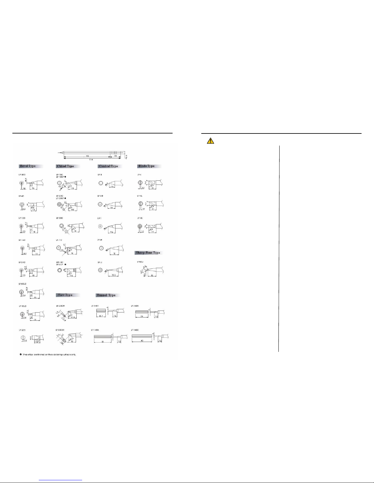
SPECIFICATIONS
ASSEMBLYANDPREPARATION
A. Handpiece
Insertthetipfullyintothehandpiece.
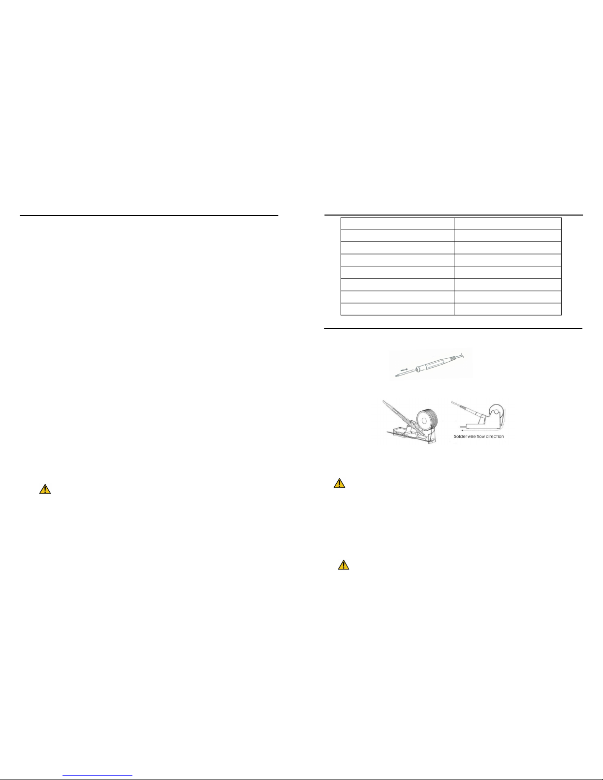
B.SolderingIron
1.Installsolderwiretothesolderironholder.
2.Attachthesolderingirontothe5pinoutputatthebottomrightareaofthestation.
3.Placesolderingirontothesolderingironstandasshowninthefigureabove.
Dampen the sponge with water and squeeze dry before using. The tips
maybedamagedwhenusedwithdrysponge.
C.SolderingStation
1.Insertthepowercordintothereceptacleatthebackofthestation.
2.Adjustrequiredvoltagefromtheredswitchatthebackofthestation.
3. Plug the power cord into a grounded wall socket. The station is protected
againstelectrostaticdischargeandmustbegroundedforfullefficiency.
BesurethepowerswitchisOFFbeforeconnectingordisconnectingthe
Powercord.Failuretodosomayresultindamagetothecircuitboard.
PowerInput: 110Vor220Vadjustable
PowerConsumption: 70W
SolderingIronOutputVoltage: 24V
SolderIronTemperatureRange: 200480o
C
TiptoGroundResistance: < 2 W
TiptoGroundPotential: < 2mV
Dimension: 110(w)x90(h)x155(d)mm
Weight: 3Kg