aoyue 968A+ User manual

20
Manufacturer:
AOYUETONGYIELECTRONICEQUIPMENTFACTORY
JishuiIndustrialZone,Nantou,ZhongshanCity,
GuangdongProvince,P.R.China
http://www.aoyue.com
DELUXEREPAIRINGSYSTEM
968A
INSTRUCTION MANUAL
ThankyouforpurchasingAoyue968A+RepairingSystem.
Itisimportanttoreadthemanualbeforeusingtheunit.
Pleasekeepmanualinaccessibleplaceforfuturereference.
CAUTION
Thetemperatureofthesolderingiron,hotairgunandthenozzlerangesfrom200
o~480
o
C
(400
o ~850
o
F)whentheunitisswitchedON.Injurytopersonnelordamagetoitemsinthe
workplace may result if not carefully used. Please read the contents on how to use the
equipmentandobservethefollowinginordertomaximizeusage:
● Afteropeningthepackage,checkifeach componentisingoodworkingcondition.If
thereareanysuspecteddamages,donotusetheitemandreportthistothedealer.
● Turn OFF the power switch and unplug the unit from the main power source when
movingtheequipmenttoanotherlocation.
● Donotstrikeorsubjectthemainunittoanyphysicalshock,includingthehotairgun,
solderingironoranypartsofthesystem.Usecarefullytoavoiddamageinanyparts.
● Makesuretheunitisgrounded.Alwaysconnectpowertoagroundedreceptacle.
+
aoyue
®

2
TABLEOFCONTENTS
Package Inclusion ………………...……………………….. 3
Functions and Features ………………..………….......... 4
Product Specifications …….…………………...……….. 5
Care and Safety Precautions ……………………..………. 6
Panel Controls ……………………………...……...…........ 7
Preparation …………………………………………………… 8
Operating Guidelines ...……………………………….. 914
Care and Use of the Tip ……………………….…...……… 15
Maintenance ……………………..………..……………. 1617
Basic Troubleshooting Guide ………………………… 1819
19
BASICTROUBLESHOOTINGGUIDE
PROBLEM 5: AIR PRESSURE LEVEL IS SIGNIFICANTLY LOW NO
MATTERHOWHIGHTHEAIRFLOWLEVELISCALIBRATED
Case 1: Check the mains voltage (AC power source). If the voltage
level falls significantly low, about 1520% lower than the standard,
therewillalsobeanoticeabledropintheairpressurelevel.
SOLUTION:Pleaserefertoyourlocalpowerserviceprovider.
Case 2: The microcontroller might have detected the operating
frequencyincorrectly.Theairflowlevelisnoticeablyweaker.
SOLUTION: Trytopressthe“Reset”buttononthepanelandletthe
deviceredetecttheproperoperatingfrequency.Notethatresettingthe
devicewillalsoresetallpreviouslydefinedconfigurations.
PROBLEM6:THESOLDERINGIRONDISPLAYS“Pen”or“Err”
Case 1 “Pen”: Soldering iron is not properly connected to the unit,
unplugsolderingironandreattachtoconnector.Solderingironsensors
mayhasbeendamageandneedstobereplaced.
Case 2 “Err”: Solderingironcannotreachthedesiresettemperature,
sensor could have been shorted due to wrong connection or heating
elementhasreachedtheendofitlife.
SOLUTIONS:Checkinternalpenconnection,replaceheatingelement.
PROBLEM7:DISPLAY&OTHERDEVICEOPERATIONISSUES
SOLUTION: Trytopressthe“Reset”buttononthedevice.Notethat
resettingthedevicewillalsoresetallpreviouslydefinedconfigurations.
OTHERPROBLEMSNOTMENTIONED:
Contactthevendor.

18
BASICTROUBLESHOOTINGGUIDE
PROBLEM1:THEUNITHASNOPOWER
1. CheckiftheunitisswitchedON.
2. Checkthefuse.Replacewiththesametypeiffuseisblown.
3. Checkthepowercordandmakesuretherearenodisconnections.
4. Verifythattheunitisproperlyconnectedtothepowersource.
PROBLEM2:TEMPERATUREDISPLAYISALWAYSABOVE500
o
C
Description: Constant display of above 500
o
C temperature from the
panel C3 then displays a blinking “OFF” on display panels C2 and C3
afterafewminutes.
SOLUTION:
Thethermalsensormaybebrokenandneedstobereplaced.
PROBLEM3:ACTUALAIRTEMPERATUREISNOTINCREASING
Description: Actual temperature reading is not increasing or
decreasing based on desired level (set temperature). The panel will
thendisplayablinking“OFF”ondisplaypanelsC2andC3afterwards.
SOLUTION:
Theheatingelementmaybebrokenandneedstobereplaced.
PROBLEM 4: BANNER OR PRODUCT NAME IS ALWAYS SCROLLING
THEUNITISNOTUSABLE
Description:Theproductnameisjustalwaysscrollingfromthedigital
panel,renderingthedeviceunusable.
SOLUTION: Press “Reset” from the panel. Note that resetting the
device will also reset all previously defined configurations. If the
problempersists,contactthevendor.
3
PACKAGEINCLUSION
MainStation
HotAirGunand
HotAirGunHolder
SolderingIronwith
SmokeAbsorber
PowerCord
G001ICPopper
3017JFilter
Pads(6pcs.)
SolderingIron
Holderwith
SolderWire
Stand
SuctionVacuumCap
FilterVacuumCap
AirNozzles
(1124,1130,1196,1313,1197)

4
●Microprocessorcontrolledelectrostaticdischarge(ESD)safeunit.
●Easytousetouchtypepanelcontrolswithdigitaldisplay.
●Environmentfriendly repairing system that integrates hot air gun,
solderingiron,andsmokeabsorberinonepackage.
●Builtinsmokeextractorthatabsorbsfumescreatedatthesource.
●Knobtypesolderingirontemperaturecontrolforsimpleyetefficient
workingtemperatureselection.
●Digitalcontrolanddisplayofsolderingirontemperature.
●Sleepmodeforsolderingiron.Solderingiron togointosleepmode
basedonuserdefinedduration.
●Solderirondigitalcalibration,solderingirontipscanbecalibrated+or
50 degrees. Easily adjust temperature offset with a few simple
adjustments.
●Intelligent errorreporting mechanism. Detects and informs the
personnelforproblemswiththesensorandheatingelement.
●Autocoolingfunctionality.Blowsairtocooldownthesystemtoasafe
temperaturebeforeturningOFF.
●Compatibilitywithvarioustypesofairnozzles.
●Compatibilitywithdifferentkindsofsolderingtips.
FUNCTIONSandFEATURES
17
MAINTENANCE
SPAREPARTSLIST
NOTE:
Toensuresafetyandquality,useonlygenuinepartsforreplacement.
PART# NAME&SPECIFICATION
10094 Hotairgunheatingelement
30105S Plastichandleofhotairgun
S005 Hotairguncompletehandle
20962 Hotairgunmetalpipe
P003 Diaphragmpump
C009 Solderingironheatingelement
30123S Plastichandleofsolderingiron
B003A+ Solderingironcompletehandle
20170 Tipenclosure
30181X Filterpads

16
MAINTENANCE
IMPORTANT: Unless otherwise directed, carry out these procedures
withthepowerswitchedOFFandthepowercordUNPLUGGED.
CARBONFILTER
●A filter device is installed at the vacuum outlet (see D2 of
panel controls reference page) . The filter pad should be
cleanedand replacedregularly,dependingonthe frequency
ofuse.
REPLACINGTHEHEATINGELEMENT
1. Loosen the 3 screws that secure the hot air gun handle. The
heatingelementislocatedinthemiddlepartofthehotairgun.
2. Slideofftheplastictube.
3. Disconnectthegroundwiresleeve.
4. TheQuartzglassandheatinsulationareinstalledinsidethepipe.
Loosenthecableandremovetheheatingelement.
5. Insert the new heating elementandreconnecttheterminal.Be
carefulnottorubortouchtogethertheheatingelementwire.
6. Reconnectthegroundwireafterreplacingtheheatingelement.
7. Reassemblethehandle.
NOTE: The life expectancy of a heating element is 1 year under
normaloperatingconditions.
K1 — filter drawer
K2 — active carbon filter pads (30181X)
K3 — smoke absorption nozzle
5
PRODUCTSPECIFICATION
Power Input : available in 110V & 220V
Main Station Dimensions: 188(w) x 126(h) x 250(d) mm
Weight: 5.25Kg
SOLDERING IRON
Power Consumption: 70W
Temperature Range: 200°C 480°C
Heating Element with Tip: Ceramic Heater
Output Voltage: 24V
Tip to Ground Resistance: Below 2 Ω
Tip to Ground Potential: Below 2mV
HOT AIR
Power Consumption: 550W
Temperature Range: 100°C 480°C
Heating Element Metal Heating Core
Nozzle to Ground Resistance: Below 2 Ω
Pump/Motor Type: Diaphragm Pump
Air Capacity: 23 l /min (max)
SMOKE ABSORBER
Vacuum Pressure: 600mm Hg

6
●Temperaturemayreachashighas480°CwhenunitisturnedON.
Donotusenearpaper,plastic,andflammablegasesandmaterials.
Donottouchheatedparts.
Donottouchmetallicpartsnearthetip.
●ThermalProtector
The unit is equipped with auto shutoff ability when temperature
gets too high. Theunit will automatically switch back ONwhen the
temperaturehasdroppedtoasafelevel.
●HandlewithCare
Neverdroporsharplyjolttheunit.
Containsdelicatepartsthatmaybreakifunitisdropped.
●Unplugtheunitfromthemainpowersourceifitwillnotbeusedfor
alongperiod.
Turnoffpowerduringbreaks,ifpossible.
●Useonlygenuinereplacementparts.
Turnoffpowerandletunitcooldownbeforereplacinganyparts.
●Soldering process produces smoke; use the equipment on well
ventilatedplace.
●Do not modify or alter the unit in any manner, particularly the
internalcircuitry.
CAUTION:Misusecancauseinjuryandotherphysicaldamage.
Foryourownsafety,besuretoobservethefollowingprecautions.
CAREandSAFETYPRECAUTIONS
15
CAREANDUSEOFTHETIP
CAUTION:Neverusefiletoremoveresiduefromthetip.
1.TipTemperature—Hightemperatureshortenstiplifeandmaycause
thermal shock to other components. Always use the most appropriate
temperaturewhensoldering.
2. Cleaning — Alwayscleanthe soldering tip before using. Remove any
residual solder or flux that are still adhering to the tip. Use a clean and
moistcleaningspongetoremoveunwantedresidues.Forbetterresultsour
Aoyue98and128tipcleanersaregreat alternativesforwetspongesthat
cleansasgoodaswetspongesbutdoesnotlowertiptemperaturelikewet
sponges.Contaminantsonthetiphavemanydetrimentaleffectswhichmay
impactsolderingperformance—onebeingreducedheatconductivity.
3. After Use —Alwayscleanthetip.Coatit withfreshsolderafter use.
Thisprotectsthetipagainstoxidation.
4. Neverallow the unit to stayidle at high temperature for long periods.
Thismakesthetip pronetooxidation.TurnOFFthepowerswitchifitwill
notbeusedforseveralhours.Unplugthemainunitfromthepowersource
ifpossible.
CLEANINGTHETIP
IMPORTANT:Performingthisprocedureextendslifeofthesolderingtip.
1. Setthetemperatureto250
o
C.
2. When the temperature has stabilized, clean the tip and check its
condition.Replacethetipifitisbadlywornorappearstobedeformed.
3. If the solder plated part of the tip is covered with black oxide, apply
freshsoldercontainingfluxandcleanthetipagain.Repeatuntilallthe
oxideisremoved.Coatthetipwithfreshsolderafterwards.
4. Remainingoxidessuchastheyellowdiscolorationonthetipshaftcan
beremovedwithisopropylalcohol.

14
OPERATINGGUIDELINES
SOLDERINGIRONMANUALCALIBRATION
1. Setsolderingirontodesiredworkingtemperature.
2. Wait afewminutesfor the temperatureto stabilizebeforechecking
thetemperaturedifferencewithanexternalcalibratedprobe.
3. Accessthemanualcalibration holeby removingtherubbercoverof
thecalibrationhole.
4. Useasmallscrewtoslowlyadjustthetrimmerpotentiometerthruthe
calibrationhole.
5. When tip temperature has been recalibrated. Replace rubber cover
intoposition.
SOLDERINGIRONDISPLAYGUIDE
“Pen”—Solderingironisnotdetected.
“OFF”—Solderingironfunctioniscurrentlyoff.
“Hot”— Solderingironfunctioniscurrentlyoffbutthesolderingiron
tipisstillveryhot.
“”—Solderingironiscurrentlyinsleepmode.
“t00”—Solderingironsleeptimeradjustmentmode,sleeptimeroff.
“t60”—Sleeptimeradjustmentmode,sleeptimersetat60minutes.
“001or–00”—Solderingirondigitalcalibrationadjustmentmode.
“Err”—Solderingironerror.
SOLDERINGIRONSMOKEABSORBER
1. Turn on Soldering Iron function and set to desired working
temperature.Waitforsolderingirontoreachsettemperature.
2. TurnontheSmokeAbsorberfunctionswitch.
Note:SmokeabsorberfunctioncannotbeenablediftheSMDrework
functionswitchisturned“ON”.Toutilizethesmokeabsorberfunction
theSMDreworkfunctionswitchshouldbeinthe“OFF”position.
7
A1 Airpressureknob
A2 Solderingirontemperaturedisplay
A3 Solderingirontemperatureknob
A4 Solderingironcalibrationhole.
A5 Resethotairguntemperature
A6 Hotairgunincreasetemperatureadjustmentbutton.
A7 Hotairgundecreasetemperatureadjustmentbutton.
B1 Solderingironfunctionswitch
B2 Smokeabsorberfunctionswitch
B3 SMDreworkfunctionswitch
C1 Airpressureindicator
C2 Settemperaturedisplay(Hotairgun)
C3 Actualtemperaturedisplay(Hotairgun)
D1 Solderingironterminal
D2 Vacuumoutlet
D3 Hotairgunoutput
PANELCONTROLS
A1
A2
A3
A5 A4
A6
B1 B2
B3
C1
C2 C3
D1
D2
D3
A7
aoyue Int968A+
OFF
ON
LOW
CAL
HIGH
REPAIRINGSYSTEM
TEMPERATURE
SOLDERING
IRON
SOLDERING
IRON
SMOKE
ABSORBER
SMD
REWORK
6
4
3
2
8
5
VACUUM
1
7

8
PREPARATION
A.MainPower
1.Plugpowercordintoreceptaclefoundatthebackoftheunit.
2.SwitchonthemainpowerswitchtoturnunitON.
B.SolderingIron
1.Installsolderwiretothesolderironholder(seeFigure1).
2.Attachthesolderingirontothemainunitviathe5pinoutput
terminal,D1,foundattheleftsideofthecontrolpanel.
3.Placethesolderingirontothesolderingironstandasshown
inFigure1.
C.SmokeAbsorber
Attachthesmokeabsorbing pen to thesmoke absorberoutput
terminal, D2, on the control panel. Make sure that the cord
connectionsarefreefromanytangles.
D.HotAirGun
Placethehotairguninthestandtoprepareforusage.
Figure 1. Soldering Iron stand with solder wire holder
Power
Switch
13
OPERATINGGUIDELINES
●The soldering iron display A2 will turn to “##” or “0##” ,
indicatingitisnowondigitalcalibrationmode.
●Turn the soldering iron adjustment knob to set calibration to “
00”.Thisresetsthecalibrationtozero.
●letsystemsavethecalibrationvalueintothememory.
3. Setsolderingirontodesiredworkingtemperature.
4. Wait a few minutes for the temperature to stabilize before
checking the temperature difference with an external calibrated
probe.
5. If external calibrated probe shows a higher number than the
968A+ soldering iron displayed actual temperature we input a
positive calibration number. If external calibrated probe shows a
lower number than the displayed 968A+ soldering iron actual
temperatureweinputanegativecalibrationnumber.
6. Againaccessthecalibrationmodeofthesolderingiron:
●EnsurethattheSMDandSmokeabsorberfunctionswitchisoff.
●EnsurethatSolderingironfunctionswitchison.
●PressandholdthehotairtemperatureincreasebuttonA6.
●The soldering iron display A2 will turn to “##” or “0##” ,
indicatingitisnowondigitalcalibrationmode.
●Turn the soldering iron adjustment knob to set the desired
calibrationvalue.
●Letsystemsavethedesiredcalibrationvalueintothememory.
7. Calibrationnumberscanbeadjustedfromnegative50topositive
50.Ifthedigitalcalibrationnumberisinsufficientforcalibration.
Themanualcalibrationoptionisavailableformacroadjustments

12
OPERATINGGUIDELINES
●Toletsystemsavethedesiredsleeptimervalueintothememory,
simply let go of the adjustment knob and the system will
automaticallysavethevalueintoCPUmemory.
3. Turn on the soldering iron function switch to start using the
solderingiron.
4. The sleep timer will start counting down once the soldering iron
function switch is turned ON and no adjustments are made to
solderingironsettemperature.
5. When the timer expires, the soldering iron will shut down its
heater and display three dashes “ “. This indicates the
solderingironisinsleepmode.
6. TowakethesolderingironsimplyadjustthetemperatureknobA3.
7. Todisablethesleeptimersimplysetthesleeptimerdurationto0.
8. Accessanddisablethesleepfeatureofthesolderingiron:
●TurnSolderingiron,SMDandSmokeabsorberfunctionswitchoff.
●PressandholdthehotairtemperatureincreasebuttonA6.
●The soldering iron display A2 will turn to “t##” ,indicating it is
nowonsleeptimeradjustmentmode.
●Turn the soldering iron adjustment knob completely counter
clockwisetosettimerto“t00”.
●letsystemsavethedesiredsleeptimervalueintothememory.
SOLDERINGIRONDIGITALCALIBRATION
1. Thesolderingironhasadigitalcalibrationfeaturethatallowsthe
usertoeasilyadjustthetemperatureoffsetofthesolderingiron+
or—50degrees.
2. Restthecalibrationnumberofthesolderingiron:
●TurnSMDandSmokeabsorberfunctionswitchoff.
●TurnSolderingironfunctionswitchon.
●PressandholdthehotairtemperatureincreasebuttonA6.
9
SMDREWORKING
1. EnsureAllfunctionswitches(B1,B2,B3)areinoffposition.
2. With the unit plugged to the main power source, turn on the
systembyswitchingthemainpowerswitchon.Thepanelshould
initially display the product name in a scrolling manner and
displayOFFonpanelC2after.
NOTE:
Theproductnamemayscrollmorethanonceuponpluggingthe
system to the power source. The system is trying to determine the
appropriate operating frequency based on the user location. See Basic
TroubleshootingGuide(page1415).
2. TurnONthe“SMDRework”functionswitch,B3.
3. Thesystemwillstarttoblowhotairandincreasethetemperature
to 90°C, by default. Display panel, C2, shows the userdefined
(set) temperature while display panel, C3, shows the actual
temperatureofthesystem.
4. Adjust air pressure by turning knob A1. It is recommended to
keep the knob settingat3 or above. Itis also advised to adjust
the airflow level first before increasing the air temperature to
avoid building of toomuch heaton the hot air gun thus burning
theheatingelement.
NOTE:
If air pressure knob is set to minimum upon switching the SMD
Rework ON, thesystem will automatically run at average airflow to protect
thedevicefromexcessiveheat.Theuserwillgainfullcontroloncetheknob
hasbeenadjustedtothedesiredairflowlevel.
OPERATINGGUIDELINES

10
OPERATINGGUIDELINES
5. SetthedesiredairtemperatureusingbuttonsA6andA7.
6. You may start reworking as soon as the desired temperature is
reached.RefertodisplaypanelC3toverify.
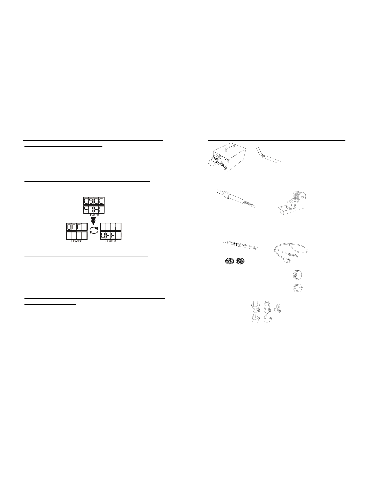
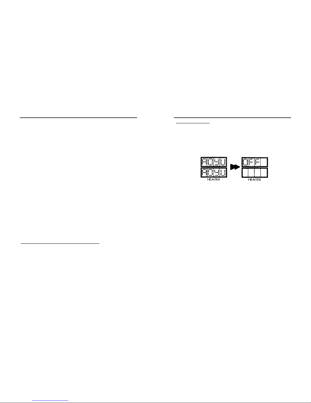
7. When reworking is completed, turn off the “SMD Rework”
function switch. The autocooling functionality will commence if
thesystemdetectsatemperaturehigherthan95°C.Itwillblowat
fullspeedtoacceleratethecoolingdownofthehotairgun.The
autocooling functionality will stop when the temperature of the
hot air gun reaches about 95°C or below, as shown from the
actualtemperaturedisplaypanel,C3.Thesystemwillthenswitch
offanddisplayan“OFF”messagefromuserdefinedtemperature
displaypanel,C2.
NOTE:
MakesurethesmokeabsorptionfunctionalityisswitchedOFFwhen
usingtheequipmentforSMDRework.
SOLDERINGIRON
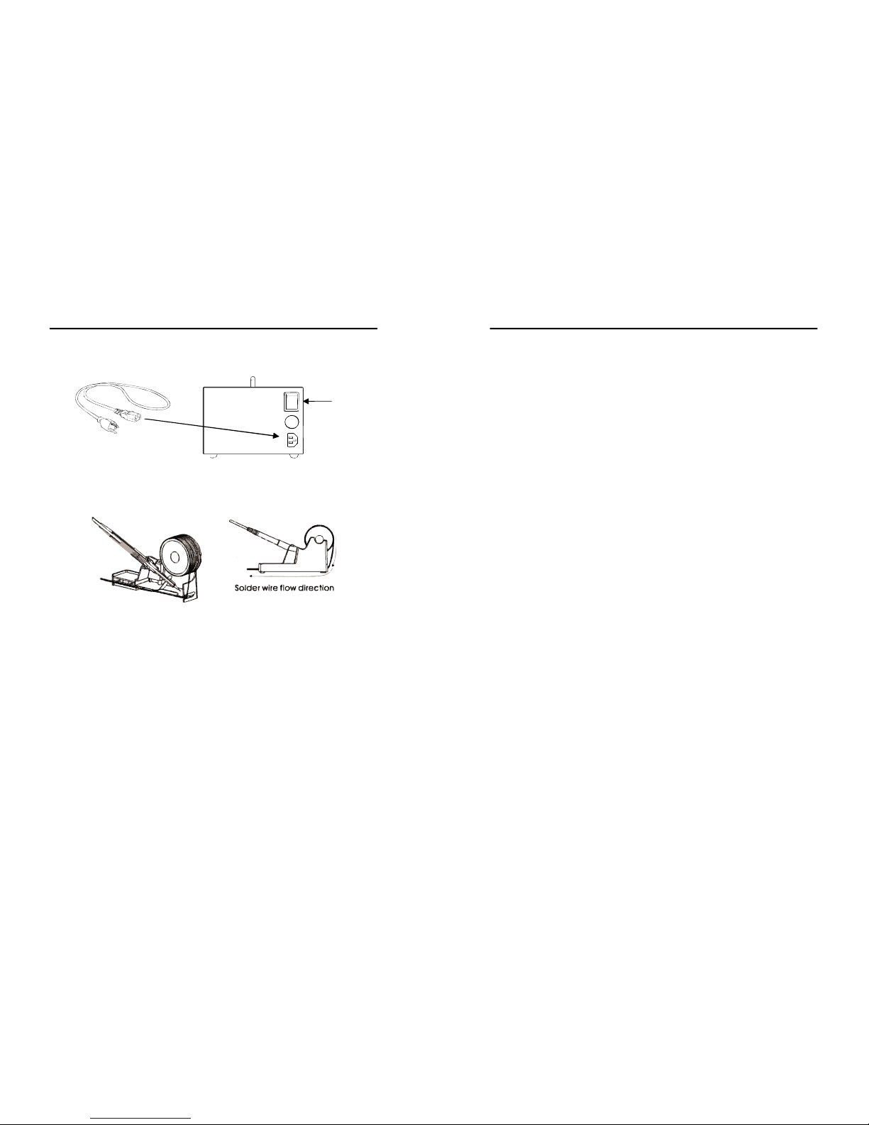
1. Withtheunitpluggedtothemainpowersourceandmainpower
switch in the ON position, ensure that the soldering iron is
properlyconnectedtothereceptacle,D1.
2. ThesolderingirondisplayA3willshowtheword“OFF”indicating
thesolderingironfunctionisturnoff.
3. TousethesolderingironturnONthe“SolderingIron” function
switch,B1.
4. The soldering iron display A3 will briefly show the current set
temperaturethenswitchtodisplayingtheactualtemperature.
5. When we use the adjustment knob, A3, to set the desired
soldering temperature. The digital display A2 will show the
currentsettemperaturebasedontheknobposition.
11
OPERATINGGUIDELINES
5. Aftera few seconds thedigital display A2willswitchto showing
theactualtemperature.Youmaystartsolderingwhenthedesired
temperaturehasbeenreached.Thesmalldotlocatedattheend
of the number displayed in A2 signifies the heater regulation.
When the small dot starts blinking on and off the system has
reachedthedesiredsettemperature.
6. Afterusageturnoffthesolderingironfunctionswitch.
7. If the soldering iron tip is still higher than 100 degrees, the
soldering iron display will show the word “Hot” indicating the
solderingironisstillhottocautionusers.
8. When the soldering iron tip’s temperature has fallen to
manageablelevelthedisplaywillshowthework“OFF”
9. SwitchONthe“SmokeAbsorber”powerswitch,B2,toactivate
thesmokeabsorptionfunctionality.
NOTE:
Turnthe“SmokeAbsorber”ONonlyafterthesolderingironreached
the desired (set) temperature. This is to avoid affecting the temperature
increaseofthesolderingironintermsofheatingtime.
SOLDERINGIRONSLEEPTIMER
1. The soldering iron has a sleep feature that allows the soldering
iron to go into sleep mode depending on user programmed
duration.
2. Toaccessandenablethesleepfeatureofthesolderingiron:
●TurnSolderingiron,SMDandSmokeabsorberfunctionswitchoff.
●PressandholdthehotairtemperatureincreasebuttonA6.
●The soldering iron display A2 will turn to “t##” ,indicating it is
nowonsleeptimeradjustmentmode.
●Turnthesolderingironadjustmentknobtoselectdesiredsleep
timeinminutes.
Table of contents
Other aoyue Soldering Gun manuals

aoyue
aoyue Int701A++ User manual

aoyue
aoyue 2900 User manual

aoyue
aoyue Tesla Series User manual

aoyue
aoyue Int936A User manual

aoyue
aoyue SP2000 User manual

aoyue
aoyue INT 2703A+ User manual

aoyue
aoyue SP2000+ User manual

aoyue
aoyue 8011 User manual

aoyue
aoyue SP4000 User manual

aoyue
aoyue 937 Plus User manual