4
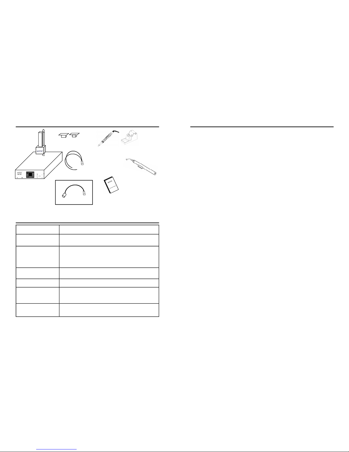
The Aoyue Int732 Game Console RepairingSystem is a reworking equipment
thatutilizesinfrared(IR)heatingtechnology,toprovidetopandbottomheatingto
the target components. It is equipped with a versatile board holder, Lead free
compatiblesolderIron,andsoftwareprofilecontrolofheatinginone sophisticated
package. It is designed for reworking doublesided, diverse technology printed
circuitboards(PCB)whichutilizestraditionalorleadfreesolder.
The system is equippedwith High powered IRheating elements combined
with multiple types of operating mode to fit various task. Finally, the unique,
innovativedesignwithdigitalcontrolpaneloffersprecision,safety,andeaseofuse
tomeetallreworkingrequirements.
PRODUCT DESCRIPTION
●Complete Game Console Repairing System.Combines large area bottom
heater, high powered topheater andlead free compatible solder iron in one
package.
●Threedifferenttypesofoperationtosuitedifferentneeds:
Type0–Forreballingorprebakingtheboard.Usesinternalsensors.
Type1–Allowsmanualcontrolofthereworkprocess.Usesexternalsensors.
Type2–Automatedreflowingprocessutilizingtheuserconfigurableprofile.
●ClosedLoopTemperatureControlwithThreeExternalSensors
—Sensorsattachedtotheboardallowsprecisetemperaturecontrolatboard
level minimizing damage to board due to inaccurate temperature settings or
overheating. Two sensors are used as temperature control and monitoring,
while an extra sensor is added to allow additional monitoring of other
temperaturesensitiveareasofthePCB.
●EnhancedTopandbottomheater
310x310mmeffectivebottomheatingarea.1500wattsofpreheatingpower
minimizesboardwarping.
60x60mmeffectivetopheatingarea.500wattsmaximumheatingpowerwith
variousnozzlestofitdifferentBGAsizes.
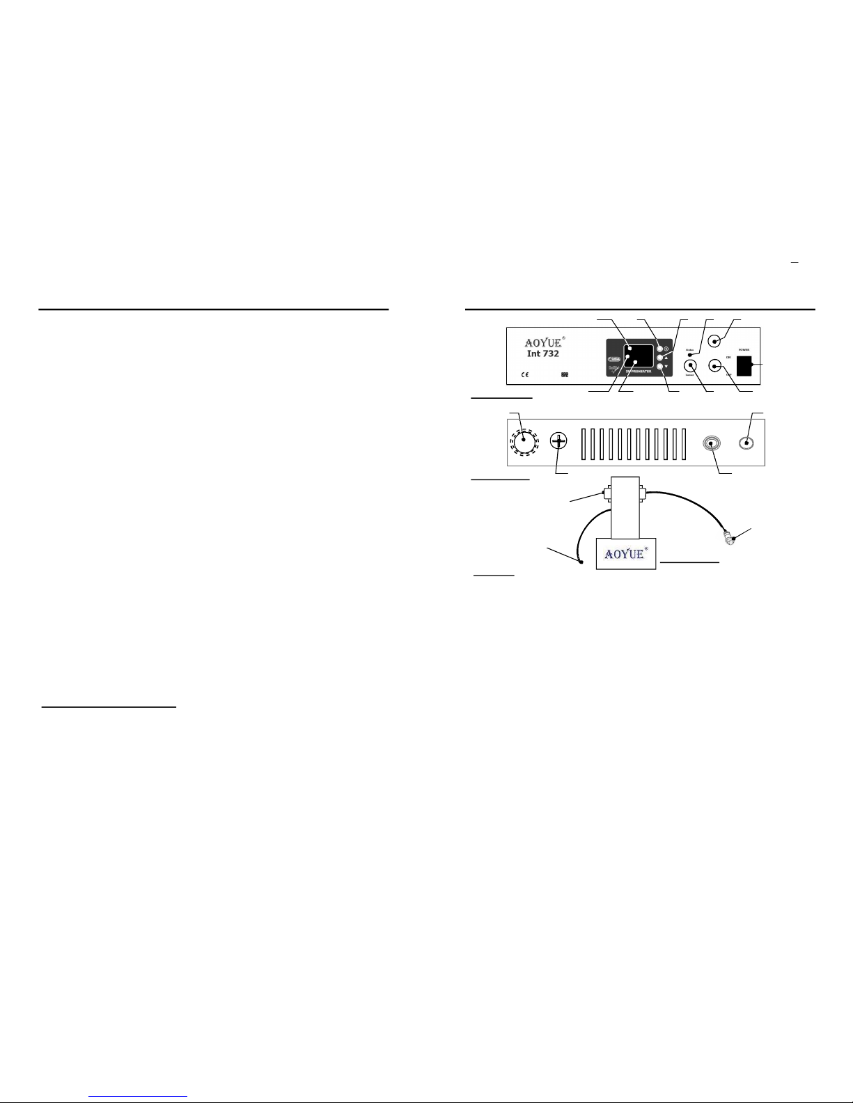
FUNCTIONS and FEATURES
13
OPERATING PROCEDURES
Note: Duringsegments13thetopheaterheatsupto75%ofthesettemperature
at these segments. This is to allow a faster ramp up inpreparation for reflow for
segments46.
1. Toentertype“2”operation.Select2attheinitialscreenthenpresstheselect
button.Thedisplaywouldchangeto“SlctProf 0”.Thissignifieswearenow
inthetype“2”mode.
2. We can then select which profile we would like to use by pressing the
increaseor decrease button. The number shownat the bottom display will
changecorrespondingtoyourselection.Therearethreestoredandselectable
profile.
3. To adjust the time and temperature profile of each segment press the
selectionbuttontwice.Thetopdisplaywillshowwhichsegment“SEG1” we
are currently adjusting. The middle display will show whether we are
adjustingthe“dur” (duration/Time)or“tEMP” (temperature).Thebottom
displayshowsthevaluewearecurrentlyadjusting.Itssuffix“t”signifieswe
areadjustingthetimeortemperatureforasuffix“C”.
4. Press the increase or decrease button to adjust the desired duration and
temperature. The set temperature is adjustable from 50 to 250 C and
duration5to200seconds.
5. Afterthedurationortemperatureissetpresstheselectionbuttontomoveto
the next segment. There are six segments available each with its own
durationandtemperaturesettings.Thedurationsettingssignifiesthetimeit
willtaketoreachoursettemperaturelevel.Forexample:ifsetdurationis50t
andtemperatureissetat100C.Thenassumingtheboardtemperatureis50C
whentheautomatedreworkisinitializedthesystemwouldgraduallyincrease
board temperature by 1 Degree per second such that after 50 seconds the
boardtemperaturewouldreach100C.
6. After we have set the segments of the profile we may begin automated
reworking. To start automation repeatedly press the selection button until
thedisplayshowstheword“Run Prof 0” (thebottomdisplaynumbershould
correspondtotheselectedprofile)thenpresstheincreasebutton.A3second
countdownwillcommencebeforeautomatedreworkingstarts.