MAINTENANCE
4.Whentheunit
is
notbeingusedandtheautosleepmodeshutoff
is
notactive
Never
allowtheunittostayidleathightemperatureforextendedperiods.This
will
allowthetiptobecomeoxidized.Turnthepower
switch
OFFifitistobeoutof
serviceforseveralhours.Itisadvisabletopullthepowerplugaswell.
5.Inspectingandcleaningthe
tip
This
procedure,iffolloweddaily
will
materiallyaddtotip
life.
1.
Setthetemperatureto
250°C.
2.
When
thetemperaturestabilizes,cleanthetipandcheckitscondition.Ifthetip
isbadlywornor
deformed,
replaceit.
3.
Ifthesolderplatedpartofthetipiscovered
with
blackoxide,applyfreshsolder
containing
flux
andcleanthetipagain.Repeat
until
alltheoxideisremoved
thencoatthetip
with
freshsolder.
/$\
Never
file
thetiptoremoveoxide.
4.Turn
thepower
OFF
andremovethetipusingtheheatresistantpad.Setthe
tipasidetocool.
5.
Remainingoxidessuchastheyellowdiscolorationonthetipshaftcanbe
removed
with
isopropylalcohol.
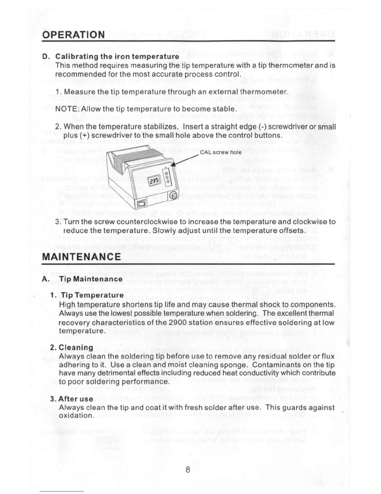
B.CheckingProcedure
Δ
Unless
otherwisedirected,carryouttheseprocedures
with
thepower
switch
OFF
andthepowercord
UNPLUGGED.
•
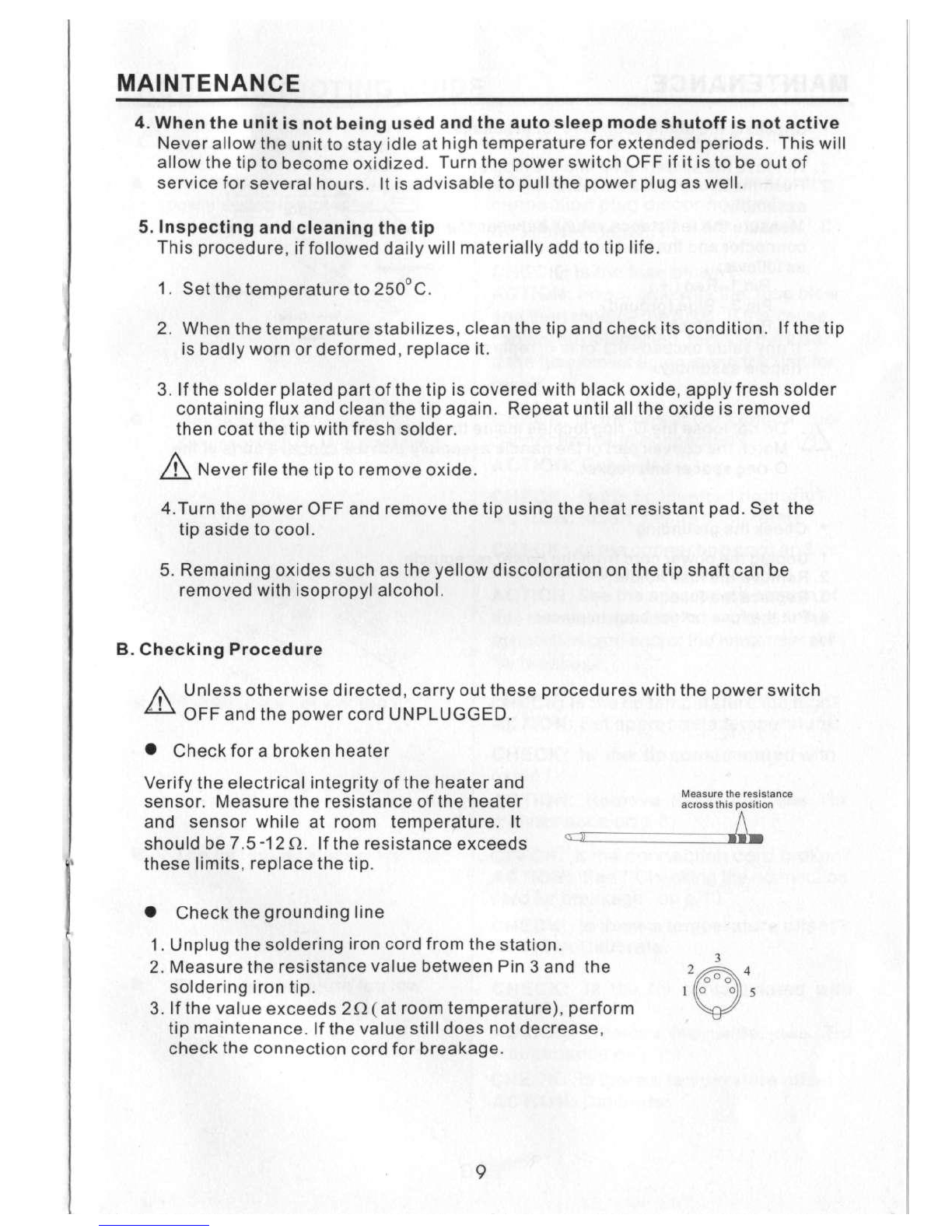
Checkfora brokenheater
Verifythe
electrical
integrity
oftheheaterand
sensor.
Measuretheresistanceoftheheater
and
sensorwhileatroomtemperature.It
should
be
7.5-12Ω.
Iftheresistanceexceeds
these
limits,
replacethetip.
•
Checkthegroundingline
1.
Unplugthesolderingironcordfromthestation.
2.
MeasuretheresistancevaluebetweenPin3 andthe
solderingirontip.
3.
Ifthevalueexceeds
2
Ω (atroomtemperature),perform
tipmaintenance.Ifthevalue
still
doesnotdecrease,
checktheconnectioncordforbreakage.
Measure
the
resistance
across
thisposition
9